

USER MANUAL
MAGLINK LX
Rev. 9 – 04-2016

This page is left intentionally blank.

Maglink LX
S
UMMARY
User Manual | Summary
1 PREFACE ............................................................................................................................................................. 4
2 GENERAL WARNINGS ......................................................................................................................................... 4
3 INTRODUCTION .................................................................................................................................................. 5
4 GENERAL DESCRIPTION ...................................................................................................................................... 7
4.1
L
ABELLING AND TYPE DESIGNATION
4.2
D
ESCRIPTION
4.3
C
OMPATIBLE PROBES
5 INTENDED USE AND REASONABLY FORESEEABLE MISUSE .................................................................................. 9
6 POWER ON/OFF ................................................................................................................................................10
7 OPERATION .......................................................................................................................................................11
7.1
F
UNCTIONS
7.1.1 Tanks ........................................................................................................................................................... 13
7.1.2 Tank details ................................................................................................................................................. 14
7.1.3 Location....................................................................................................................................................... 22
7.1.4 List of ON/OFF sensors ................................................................................................................................ 23
7.1.5 Alarm Log .................................................................................................................................................... 24
7.1.6 INFO ............................................................................................................................................................ 25
8 MANUAL UPDATE PROCEDURE .........................................................................................................................27
9 PRINT INVENTORY .............................................................................................................................................28
......................................................................................................................................................... 7
.............................................................................................................................................. 8
......................................................................................................................................................... 12
............................................................................................................................ 7
10 SHIFT REPORT....................................................................................................................................................29
11 MAINTENANCE ..................................................................................................................................................30
12 SUPPORT ...........................................................................................................................................................31
13 SAFETY INSTRUCTIONS ......................................................................................................................................32
14 CERTIFICATION ..................................................................................................................................................33
15 NOTIFICATION ...................................................................................................................................................37
16 REVISIONS .........................................................................................................................................................38
Rev. 9, 04-2016
Page 3 of 40
Maglink LX
1 P
Start Italiana S.r.l. has made every effort possible so that this document is complete, accurate and updated.
With every revision of the console, the corresponding information is periodically added to the document.
Start Italiana S.r.l. reserves the right to make unannounced improvements and/or changes in the product
and/or associated programs. Start Italiana S.r.l. is not liable for damages of any kind, including those
resulting in the document, including typographical errors.
Making copies, citing quotes or other reproductions of all or part of this document is permitted only after
written consent of Start Italiana S.r.l.
Trade mark or name is protected by patents.
Copyright 2015© Start Italiana S.r.l. – All rights reserved
REFACE
«Manual_name»l | Preface
2 G
Before working on this equipment, please be certain to carefully read the instructions in this manual.
Configuration must be performed by properly trained personnel.
The manufacturer is not responsible for any operation performed which is not covered in this manual.
Any tampering with the equipment and software relieves the manufacturer of any responsibility in regards
to competent bodies.
In case of failure or defect, refer to an authorized service provider or manufacturer directly.
The manufacturer accepts no responsibility for any injury and/or damage to persons and/or property
and/or pets caused by failure to follow instructions relating to safety.
Qualified and trained staff has to know all safety requirements in this manual, in the user manual and in the
installation manual.
In case of doubt concerning the operation of the equipment, refer to an authorized service provider or
manufacturer directly.
ENERAL WARNINGS
IMPORTANT: It is compulsory to consult safety instructions before using the equipment
IMPORTANT: Improper use, not in accordance with the requirements described herein, may
compromise safety
Rev. 9, 04-2016
Page 4 of 40
Maglink LX
3 I
This manual has been prepared in accordance with IEC 82079-1 standards. “Preparation of instructions for
use - Structuring, content and presentation - Part 1: General principles and detailed requirements”and
according to the ATEX Directive 2014/34/EU concerning equipment and protective systems intended for
use in potentially explosive atmospheres.
The manual provides all necessary information on using a Maglink LX console.
The following table lists the symbols used in the document:
Symbol Description
The following table lists reference data of the manufacturer:
NTRODUCTION
ATTENTION: Important information and notes regarding operations and use
considerations
IMPORTANT: Danger to persons (including death), to property or to the
environment
User Manual | Introduction
Data Description
Name Manufacturer_name
Address
Address
Telephone Tel
Fax Fax
Website www
e-Mail eMail
ATTENTION: This manual must be used in conjunction with the following manuals:
In order to use the console as described below in this manual, you must have installed the
consoles as per Installation Manual and use the console as per the Configuration Manual
20813 Bovisio Masciago (MB)Address
ItaliaAddress
• Configuration Manual
• Installation Manual
Rev. 9, 04-2016
ATTENTION: This manual must be used in conjunction with safety instructions:
IMPORTANT: Console installation should be performed by qualified/trained personnel, as
shown in the Installation Manual, Configuration Manual and according to safety instructions
Page 5 of 40
Maglink LX
User Manual | Introduction
The Maglink LX console complies with the requirements of Directive 2012/19/EC on waste of electrical and
electronic equipment (WEEE) and hence displaying the according symbol:
IMPORTANT: The crossed out wheelie bin symbol indicates that the product, at the end of
its useful life, must be disposed of with household waste and must be brought to a
collection point for electrical and electronic equipment
ATTENTION: The units of measurement contained in this manual refer to a specific choice by
the user himself/herself. You can set the measurement units in a different way (see
Configuration Manual)
Rev. 9, 04-2016
Page 6 of 40
Maglink LX
User Manual | General description
4 G
ENERAL DESCRIPTION
4.1 Labelling and type designation
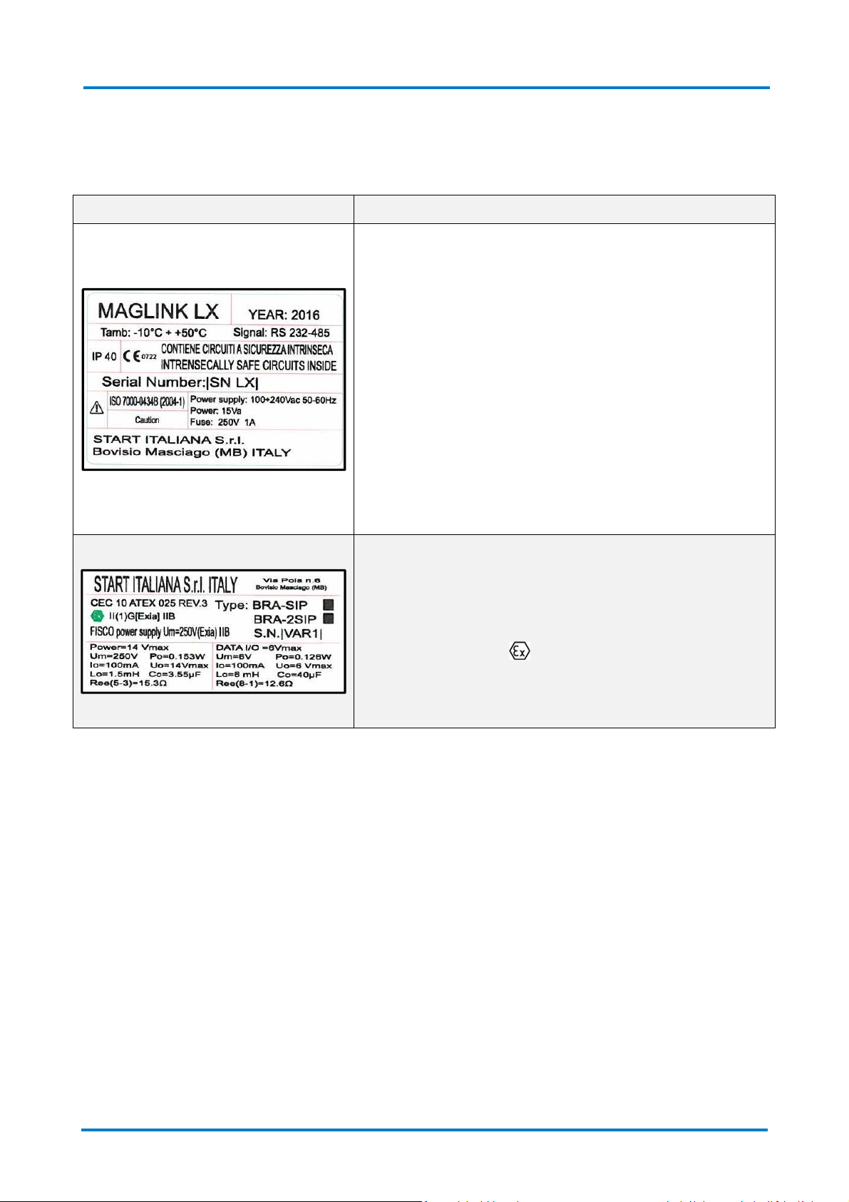
The following table lists the labels placed on the equipment:
Labelling Description
The labelling on the outer container contains the following
data:
• Name and address of the manufacturer
• CE marking with the Notified Body
• Product Name
• The "Caution" symbol (0434B of 01/2004), according to
ISO 7000
• Serial number
• Year of production
• Power Supply(VAC and Hz)
• Power consumption (VA)
• Operating temperature (°C)
• Ingress protection (IP grade)
• Fuse rating
• Indication that inside there is intrinsically safe circuit
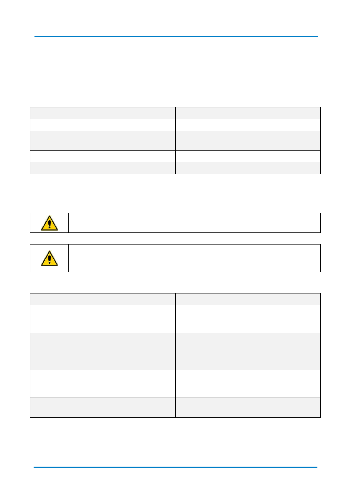
ATEX labelling on the outer container contains the following
data:
• Name and address of the manufacturer
• Equipment Type (BRA-SIP, or BRA-2SIP)
• ATEX Reference number of the certificate
• ATEX Marking: II (1) G [Exia] IIB FISCO power supply
UM=250 V [Exia] IIB
• Serial number
• Electrical data
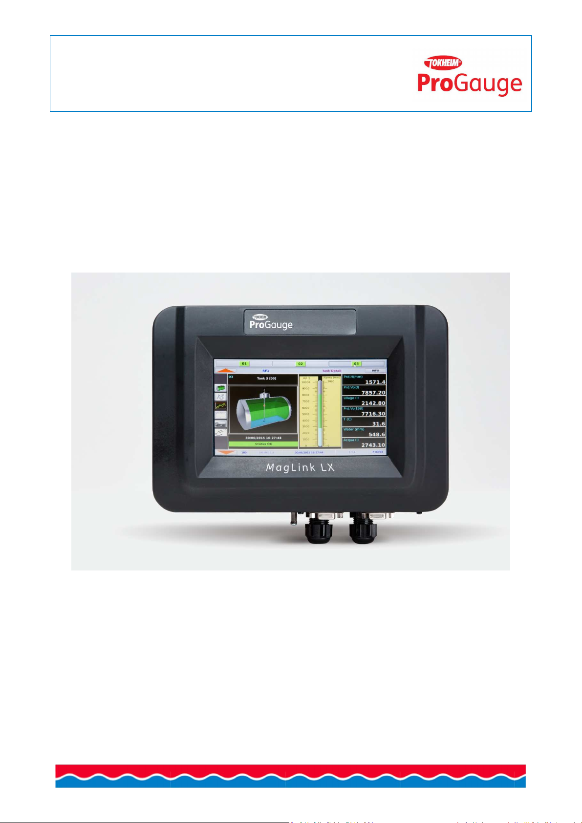
4.2 Description
The console is a device for the monitoring of the level of probes and for signalling the relative tank alarms.
32 probes can be supported, 16 on-board (8 with the addition of a MagDirect ,Max 2 MagDirect), 32 DVD
(Fuel Quality Sensors, one for each tank), 4 on board relays, 6 inputs on board, and an external expansion
module that can carry up to 4 expansion cards. Each expansion card supports 8 relay outputs, 8 Digital
Inputs or 4-20mA. With a combination of these cards the system can support 32 relays and 0 inputs, 32
inputs and 0 relays, and combinations of both with modularity of 8.
The console can be interfaced with the FCC/POS on the station via either serial or Ethernet.
The console is equipped with a resistive type touch screen, so it is possible to use it with fingers (even with
gloves), special pens and likewise. It required to contact and apply a pressure to use it.
Rev. 9, 04-2016
Page 7 of 40

Maglink LX
User Manual | General description
The following table lists the principal technical characteristics of the console:
Characteristic Value
Power supply 100 ÷ 240 V~, 50÷60 Hz
Consumption 15 VA
Operating temperature (-10 ÷ +50) °C
Relative humidity (5 ÷ 95)%, non-condensing
Number of probes 32
Number of ON-OFF external sensors Up to 32
Number of ON-OFF internal sensors 6 (only with Dipswitch 2 on ON)
External relay outputs Up to 32
Internal relay outputs 4
Lower power of the relay output 0,5 A, 33 V~, or 2 A, 30 V DC
Output power for the probes
12 V DC, 100 mA per output per probe, connectors
MR3 MR4 (up to 8 probes per connector)
Serial communication of the probes RS485
Host communication (management) RS232
Printer communication and management software RS232
Integrated web server for configuration,
consultation, communication, and emails.
TCP/IP
GSM modem for SMS service 1 Optional
IFSF 1 Optional
Case Plastic
Protection IP40
Dimensions 265 x 190 x 95 mm
4.3 Compatible probes
The following table lists the probes compatible with the MAGLINK LX console:
Probe
XMT EXD 485
XMT SI 485
XMT RF (RF receiver required)
The following table lists the auxiliary equipment of the MAGLINK LX console:
Auxiliary equipment
Expansion cards, up to 32 relays and 0 inputs, up to 32 inputs and 0 relay, and various combinations in
modules of 8
Local printer
Rev. 9, 04-2016
Page 8 of 40
Maglink LX
5 I
The intended use for the MAGLINK LX console is only for that described in this manual.
The console is used for monitoring the level of the probes installed in the tanks.
The console must be installed in a safe area and includes an Intrinsic safety barrier, 2 channels (BRA-2SIP)
that serve to connect the XMT-SI-485 probes
The following table lists the characteristics of use of the intrinsically safe barrier contained in the console:
MAGLINK LX Features (barrier) Description
Group (area of use) II (Surface industries different from mines)
NTENDED USE AND REASONABLY FORESEEABLE MISUSE
User Manual | Power On/Power Off
Category and type of potentially explosive
atmosphere
Protection mode ia
Group of substances (gases, vapours or mists) IIB
The specifications of use for console security and for the Barrier are provided in this manual and on the
product label.
IMPORTANT: Safety instructions constitute an attachment to this manual and users must
acknowledge it before using the equipment
IMPORTANT: The Console should not be used in areas at risk of fire and explosion. The
probes of the XMT-SI-485 family are installed in risk of fire and explosion areas and must be
connected to the Barrier contained in the console itself.
The following table lists some reasonably foreseeable incorrect uses:
Element considered Incorrect use
(1) G
Resistive touch screen
USB and USB Port devices
Serial ports
Network cable
Rev. 9, 04-2016
Do not use for selection of options other than your
fingers and/or special accessories intended for
resistive touch screens
Do not use other USB devices than those formatted
as FAT 32
Do not connect the printer, PC, tablet, mobile phone
to the USB ports
Do not use serial ports other than for the printer
and PC with management programs that interface
with the protocols provided by Start Italiana S.r.l.
Do not use the other network cable to connect your
PC or the corporate network
Page 9 of 40
Maglink LX
6 P
The following table lists the steps necessary to switch on the console:
When switched on if the console is not configured it will emit an alarm when it does not communicate with
any tank. Press the red arrows up and down until you reach the page "ALARM LOG" and press the ACK
button to silence the alarm.
For any changes to be made to the console configuration, refer to the manual "Configuring the Console.”
The following table lists the steps necessary to switch off the console:
OWER
Step Description
1 Check that the power button is OFF (0)
2 Connect the power cable.
3 Connect the corporate network cable, if required
4 Press the power button ON (1)
ON/OFF
IMPORTANT: Only authorized/trained personnel following the installation inline with the
manufactures instructions can switch on the console. This operation must be in accordance
with the instructions of the Installation Manual and according to Safety Instructions.
User Manual | Power On/Power Off
Step Description
1 Press the INFO button at the top right of the screen
2 Press the "Off" button within the INFO page
3 Wait for the screen to turn black
4 Press the power OFF (0) button on the console
IMPORTANT: If the console is switched OFF simply removing power the SD card might be
damaged and the console might not restart. If this happen a new SD card is needed and the
image of the Operating System and application should be loaded, and at last the backup
restore in order to have the previous saved configuration
The Console needs to be shut down from info page before removing power for proper
operation.
Rev. 9, 04-2016
Page 10 of 40
Maglink LX
Information
Description
Red arrow on
Circular menu including: "Tanks
,” "Tank Details
,” "Location
,” "ALARM LOG"
Tokheim
Station name
Tanks
Page Title
INFO
Button to access system information/functions
Information
Description
Red arrow below
Circular menu including: "Tanks
,” "Tank Details
,” "Location
,” "ALARM LOG"
050 Page Number
192.168.1.209
IP address of the console
Current date and time (There may
be a message about the static/dynamic
2.3.3
– 2.3.0
Firmware, application and web versions
P 01/02
Tank number examined/total number of reservoirs
User Manual | Manual update
7 O
The application has an easy-to-use "circulate" menu, with which the user can browse through all the
available functions.
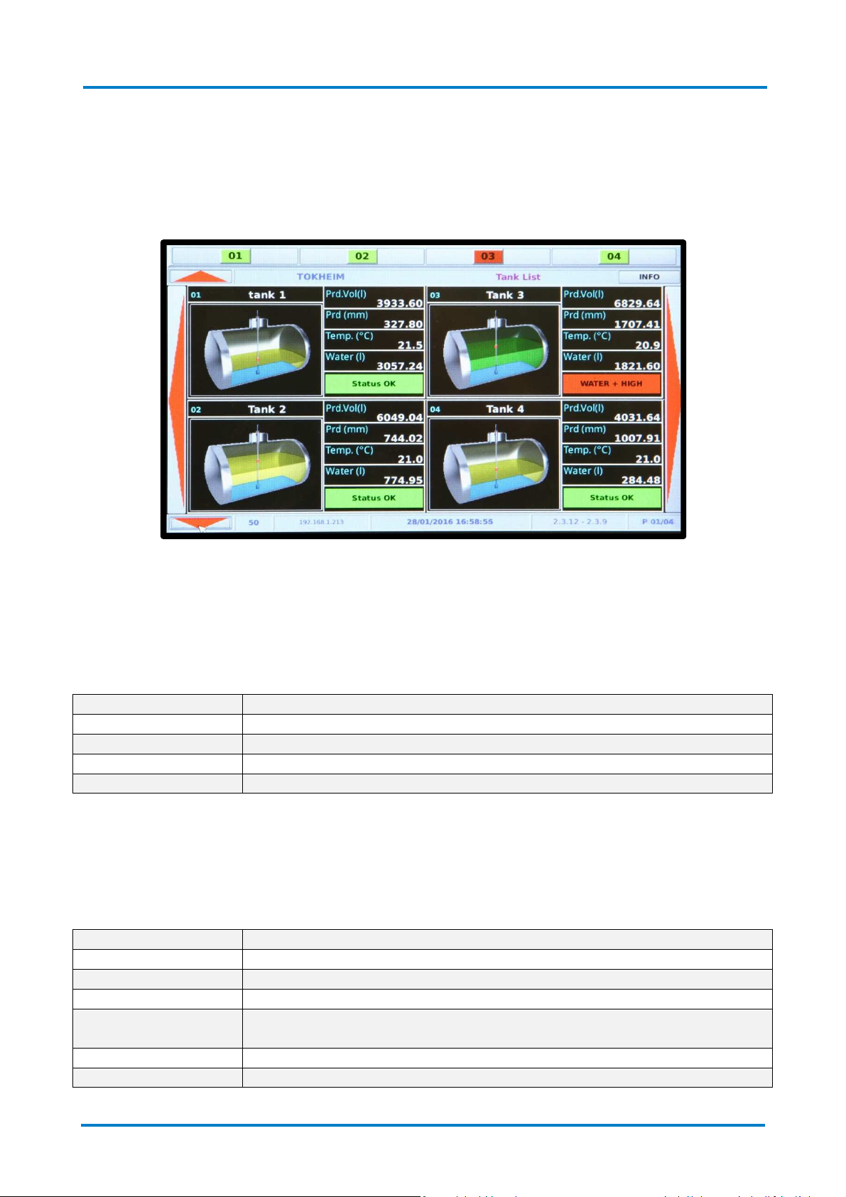
The following image shows the opening page of the console:
This page summarizes the main information relating to one or more tanks. You can view up to 4 tanks
simultaneously on the same page. If there are more than 4 tanks configured you can view the next one by
pressing the large red arrows in the left and right parts of the page.
The first line at the top of the page contains a list of tanks connected to the console: The icon colour of tank
number reflects the state of the reservoir.
The following table lists the data visible in the second row at the top of the page:
PERATION
In the central part of the page press the red right/left arrows to display the previous and/or subsequent
data of the tanks, in the case where more than 4 tanks are connected to console (The page allows
displaying 4 tanks at a time).
The following table lists the data visible in the lower row at the bottom of the page:
05/11/2015 11:44:23
Rev. 9, 04-2016
leakage/loss)
Page 11 of 40
Maglink LX
User Manual | Manual update
7.1 Functions
Using the up/down red arrows, you can access the functions of the console. The following table lists the
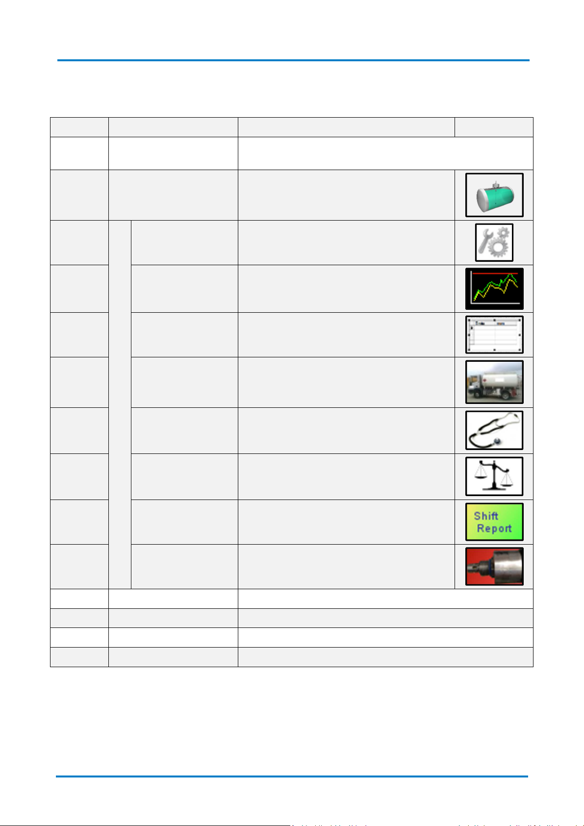
available functions:
Paragraph Function Description Icon
7.1.1 Tanks
7.1.2 Tank details
7.1.2.1
Tank Configuration Display Tank parameters
7.1.2.2 Historical chart
Display tanks connected to the console/Select tank to be
displayed
"Multi page" dedicated to a single tank with
the ability to view multiple screens
Display of trends over time for
levels/volumes/temperatures, etc.
7.1.2.3 Historical list Time display of tank levels in graph form
7.1.2.4 Delivery list Viewing the delivery list
7.1.2.5 Diagnostics Display diagnostic data
7.1.2.6 Reconciliation Display reconciliation data
7.1.2.7 Shift Report Display Shift Report
7.1.2.8 Product quality DVD View DVD data
7.1.3 Status Display tank level as a percentage for all connected tanks
7.1.4 List of ON/OFF sensors Display ON/OFF sensors connected to the tank
7.1.5 Alarm Log Display current and previous alarms
7.1.6 INFO System Information/Functions
Rev. 9, 04-2016
Page 12 of 40

Maglink LX
7.1.1 Tanks
The following image shows an example of the "Tank Page":
User Manual | Manual update
The following table lists the page elements:
Element Description
Tank graph Graphical representation of the level in the tank
The following data is displayed:
• Prd.Vol(l): Quantity of products in the tank displayed in [l]
• Prd (mm): Product level inside tank is displayed in [mm]
• Temp.(°C): Tank temperature displayed in [°C]
• Water (l): Quantity of water in the tank displayed in [l]
• Tank status (Internal alarm codes):
• OK STATUS (0)
• NO LINK (1, 8, 9, 11)
• HIGH (2)
• LOW (3)
• OUT OF RANGE (4)
Tank data
• PROBE (5)
• VERY HIGH (6)
• VERY LOW (7)
• WATER (10)
• WATER + HIGH (12)
• WATER + LOW (13)
• WATER + OUT OF RANGE (14)
• WATER + PROBE (15)
• WATER + VERY HIGH (16)
• WATER + VERY LOW (17)
• WATER + NO LINK (18, 19)
• DISABLED (30)
• NOT INITIALIZED (99)
Rev. 9, 04-2016
Page 13 of 40

Maglink LX
User Manual | Manual update
7.1.2 Tank details
The following image shows an example of the "Tank Details": (It is accessed by clicking on the graphic on
the page of this tank "Tank"):
The following table lists the page elements:
Element Description
Graphical representation of the level in the tank
The following data is displayed:
Image of the tank
• Name of the product in the tank
• Date and time of details
• Tank status
Product level graph
Graphical representation of the level in the tank, displayed in [l] and
alarm displayed in [mm]
The following data is displayed:
• Prd.H(mm): Product level displayed in [mm]
• Prd.Vol(l): Product volume displayed in [l]
• Ullage(l): Remaining product volume displayed in [l] referred
Table details
to the working capacity percentuage
• PrdVol15 (l): Compensated volume at 15° C displayed in [l]
• Temp.(°C): Product temperature displayed in [°C]
• Water (mm): Water level displayed in [mm]
• Water (l): Water level displayed in [l]
Rev. 9, 04-2016
Page 14 of 40

Maglink LX
User Manual | Manual update
7.1.2.1 Tank Details/Tank Configuration
The following image shows an example of the "Tank Configuration" (Accessed by clicking the icon on
the left):
The following table lists the page elements:
Element Description
The following parameters are displayed:
• Address probe
• Capacity (l): Capacity of tanks displayed in [l]
• Max Height (mm): Maximum height of tanks displayed in [mm]
• offset (mm): Difference between probe and dipstick displayed in
Tank details
[mm]
• Zero H2O (mm): Water offset displayed in [mm]
• Div. Vol. (l): Delivery volume detection below which nothing happens
(above, you have Delivery), displayed in [l]
• Leakage (l): Leakage volume detection below which nothing happens
(above, you have Leakage), displayed in [l]
Information Table Displays the information table in use [level (mm)/Volume (l)]
Rev. 9, 04-2016
Page 15 of 40

Maglink LX
User Manual | Manual update
7.1.2.2 Tank Detail/Historical chart
The following picture shows an example of the "Graph history" page (accessed by clicking the icon on
the left):
The page shows the trend of the tank level displayed in [mm] over a 24 hr period.
Legend (the lines are present only if the corresponding alarms are configured):
Colour Description
Blue line Water level
Higher Blue line Water alarm threshold
Lower red line VERY LOW product level threshold
Lower yellow line LOW product level threshold
Green Line Product level threshold
Higher yellow line HIGH product level threshold
Higher red line VERY HIGH product level threshold
Rev. 9, 04-2016
Page 16 of 40

Maglink LX
User Manual | Manual update
7.1.2.3 Tank Detail/Historical list
The following picture shows an example of the "Graph list" page (accessed by clicking the icon on the
left):
The following table lists the page elements, as a function of time:
Element Description
Prd (mm) Quantity of products in the tank displayed in [mm]
Prd (l) Quantity of products in the tank displayed in [l]
H2O (l) Quantity of water in the tank displayed in [l]
T (C) Product temperature dispalyed in [°C]
Tank state
• OK STATUS (0): everything OK
• NO LINK (1, 8, 9, 11): no communication
• HIGH (2): HIGH product level
• LOW (3): LOW product level
• OUT OF RANGE (4): A value that is not allowed (check tank table information)
• PROBE (5): generic problem on the probe
• VERY HIGH (6): VERY HIGH product level
• VERY LOW (7): VERY LOW product level
State
• WATER (10): Water level
• WATER + HIGH (12): HIGH water level + product level
• WATER + LOW (13): LOW Water level + product level
• WATER + OUT OF RANGE (14): Water level + a value that is not allowed (check
tank table information)
• WATER + PROBE (15): Water level + probe problem
• WATER + VERY HIGH (16): VERY HIGH Water level + product level
• WATER + VERY LOW (17): VERY LOW Water level + product level
• WATER + NO LINK (18, 19): Water level + no communication
• DISABLED (30): Probe disabled via Configuration
• NOT INITIALIZED (99): Probe not configured
Rev. 9, 04-2016
Page 17 of 40

Maglink LX
User Manual | Manual update
7.1.2.4 Tank detail/Delivery List/Losses
The following picture shows an example of the "Delivery list" page (accessed by clicking the icon on
the left):
White lines are related to Delivery, the red lines are related to losses.
The following table lists the page elements, as a function of data and time:
Element Description
Init. (l) Initial volume displayed in [l]
Final (l) Final volume displayed in [l]
Qty (l) Delivery (Amount delivered to the tank) displayed in [l]
Interval (min) Duration displayed in [min]
7.1.2.5 Tank details/Diagnostics
The following picture shows an example of the "Diagnostics" page (accessed by clicking the icon on
the left):
The data shown is for use by the support staff
Rev. 9, 04-2016
Page 18 of 40

Maglink LX
User Manual | Manual update
7.1.2.6 Tank details/Reconciliation
The following picture shows an example of the "Reconciliation" page (accessed by clicking the icon on
the left):
The following table lists the page elements:
Element Description
Time Reference time
Vol. Initial Initial time volume
Vol. Final Final time volume
Vol. Diff. Difference in volume from Start to End
Dispenser Volume dispensed by dispenser
Delta Vol Volume reconciliation value
GG +1 Selection of successive days
GG-1 Selection of previous days
The daily reconciliation will be available on reports in relation to the time programmed during the setup
phase.
Reconciliation is only available when the Console receives data from an FCC/POS supporting the
reconciliation process (dispenser sales)
Rev. 9, 04-2016
Page 19 of 40

Maglink LX
User Manual | Manual update
7.1.2.7 Tank Details/Shift Report
The following picture shows an example of the "Shift Report" page (accessed by clicking the icon on
the left):
The following table lists the page elements:
Element Description
ID Incremental shift number
Start Start of shift
End End of shift
Initial volume Opening shift volume
Final volume Closing shift volume
Delivery Volume of Delivery if present
Shift Difference in volume start-end
Rev. 9, 04-2016
Page 20 of 40

Maglink LX
User Manual | Manual update
7.1.2.8 Tank Details/DVD Details
The following picture shows an example of the "DVD Details" page (accessed by clicking the icon on
the left):
The following table lists the page elements:
Element Description
The following data is displayed:
• Tank: Tank number
Details in the first row
• DVD ID: DVD identifier
• Diagnosis: Support use only
• No.: Number of transmissions from emission
• Referral date and time of details
The following data is displayed:
• Density: Density of the product displayed in [g/ml]
• Viscosity: Viscosity of the product displayed in [cP]
• Dielectric: Product Dielectric
Table details
• Temperature: Product temperature displayed in [°C]
• Fuel ID/Biodiesel in Diesel: Product type
• Confidence index /% Biodiesel in Diesel: 100% compared
confidence value of the product in the tank of the product
with the theoretical value (Below the 50% confidence,we are
not able to recognize the product with certainty)
Detail in the last row Alphanumeric code for Start Italiana S.r.l. exclusive use
Rev. 9, 04-2016
Page 21 of 40

Maglink LX
User Manual | Manual update
7.1.3 Tank detail percentage
The following image shows an example of the "Status":
The number of the tank, the name of the tank, its state and the percentage filling of the tank are reported
on the page.
Rev. 9, 04-2016
Page 22 of 40

Maglink LX
7.1.4 List of ON/OFF sensors
The following image shows an example of the "List of ON/OFF sensors":
.
The following table lists the page elements:
User Manual | Manual update
Element Description
Sensor type:
Number
• 1 – Internal sensor (up to 6)
• 2 – Tri-state external sensor (optional)
• 3 – External expansion card from Start Italian Srl (optional)
Progressive number Progressive number on the type of sensor
Description
Sensor state
See description status of the sensor in the manual "Console
Configuration"
Sensor state description (NORMAL, NOT INSTALLED, NOT DEFINED,
CLOSED, OPEN)
Time Actual time
Rev. 9, 04-2016
Page 23 of 40

Maglink LX
Element
Description
Date
- Time
Date and time of alarm
Tank
Tank Number
Alarm
Tank status
Alarm type:
ACK Button to acknowledge all active alarms
7.1.5 Alarm Log
The following image shows an example of the "Alarm Log":
The following table lists the page elements:
User Manual | Manual update
Type
• ON (red): Active Alarm
• CLEAR (green): Resolved alarms
• ACK (yellow): The alarm is acknowledged
When each new alarm, the console emits an audible sound.
To acknowledge, the user has to open this page and press the ACK button.
The audio alarm is deactivated and the alarm is marked in yellow to signify acknowledged. If there is a relay
associated with the alarm relay, it will remain active as long as the alarm is present. The ACK button
acknowledges the audible alarm but does not change relay signalling.
Rev. 9, 04-2016
Page 24 of 40

Maglink LX
7.1.6 INFO
The following image shows an example of the page "INFO":
The following table lists the page elements at the left of the page:
User Manual | Manual update
Element Description
Version Console software version
Serial number Unique serial number of the console
IP address Unique IP address of the console
Protocol Type Communication protocol currently set
Rev. 9, 04-2016
Page 25 of 40

Maglink LX
Button
Description
Print inventory
Prints the current inventory report
Exporting the information log to a
USB device
s
(The button appears if a USB device
Download the latest
software from the USB device
(The button appears if a USB
Software update (Not present until
the upload from the USB is complete)
The
Restoring a
previous backup configuration
from the
USB device
s
(The button
Close
Close the INFO page
Power Off
Console power off
Restart
Restarts the console
application
Manual closure of the current Shift Reports and opening a new one (By pressing
Button to activate
static
Leakage control (Not present if the page "Reconciliation"
Button to activate Anti
-
theft control (Not present if the page "Reconciliation" is
The following table lists the page buttons:
User Manual | Manual update
Export Log
Download from USB
Update
To restore a previous
Backup
Close manual shift
report
Activate Static
Leakage Control
following EPA rules.
At least 2 hours is
needed to generate
the result.
The result is
generated only if a
leakage has been
detected and it is
written in the
Delivery/Leakage
page marked as red
line
Activate Anti-theft
Control.
After 10 minutes from
the activation waiting
for stabilization if
there is any loss the
console generate an
alarm
instantaneously, in
the same way done
for the Leakage
control, without
waiting the minimum
of 2 hours of elapsed
time
is connected)
device is connected
console is automatically restarted after the update.
appears if a USB device is connected The console is automatically restarted after
the update..
the button, the console displays the following message: "Closing shift reports and
opening the next one. Would you like to proceed?")
is active); Pressing the button will bring up the following window:
Enter the Serial Number of the console (6 digits) and press ENTER to confirm (Use
DEL to delete incorrect digits)
If Reconciliation is active the leakage is Dynamically activated whenever all the
nozzle are in “rest” position. If at least 2 hours elapse in this conditions then the
algorithm is activated, otherwise it will abort.
Dispenser and nozzle configuration is required for a proper operation.
active); Pressing the button will bring up the following window:
Enter the Serial Number of the console (6 digits) and press ENTER to confirm (Use
DEL to delete incorrect digits)
Remember to deactivate this functionality before starting to use the dispenser
otherwise it will trigger the alarm.
Rev. 9, 04-2016
Page 26 of 40

Maglink LX
User Manual | Manual update
8 M
ANUAL UPDATE PROCEDURE
The console can be periodically updated by downloading the latest version of the application files from the
site www.startitaliana.it (Section MagLink-LX, ZIP format).
The following table shows the necessary procedure steps for updating such data:
Step Description
Provide a USB device
1
ATTENTION: The USB device must be formatted to FAT32
2 Downloading the latest version of the application files for the START web site
3 Use a USB device with at least 50 MB of free space available
4 Connect the USB device to a PC
5 Create a folder on the USB device named "lx-update" (All in lower case)
6 Extract the ZIP file in the "lx-update" USB device
7 Connect the USB device to the console
8 Press the "INFO" button and access the relevant page
9
Wait until the "Download from USB" appears on the screen and then press it (The files on the
device are copied to the console)
10 Press the "Update" button to apply the update
11 The update process is completed with the reboot of the console
Rev. 9, 04-2016
Page 27 of 40

Maglink LX
9 P
The console can be connected to a Sprint serial printer through the RS232 serial port. Once connected, the
user can print the current inventory .
RINT INVENTORY
User Manual | Print inventory
The following table shows the necessary procedure steps for printing stock:
Step Description
1 Connect the Sprint printer to the console RS232 port using a CX cable
2 Press the "INFO" button and access the relevant page
3 Press the button "Print stock" and wait for printing
Via the console configuration you can turn on automatic printing of various events such as:
• Alarms
• Shift report
• Delivery
• Losses
• Reconciliation
Refer to the Configuration Manual.
Rev. 9, 04-2016
Page 28 of 40

Maglink LX
10 S
The console can produce a Shift Report.
The shift report can be manually triggered or it can be automatically configured. You can configure multiple
daily Shift reports.
The following table shows the necessary procedure steps for managing such Shift Reports:
HIFT REPORT
Step Description
1 Press the "INFO" button and access the relevant page
User Manual | Shift Report
2
You can access the page "Shift Report" and view the daily Shift Report data of, as per paragraph 7.1.2.7
"Tank Details/Shift Report.”
If you have configured the automated Shift reports by manually pressing Closure of Shift Reports from the
Info Page this closes the Shift Report in progress and opens the next one which will then be automatically
closed at the next scheduled date.
If a delivery is in progress, the value of the final volume of the Shift Report is equal to the volume in tanks
prior to commencement of Delivery.
Press the button "Close shift report" and confirm the subsequent message (The current Shift
Report is closed with a new shift automatically started)
Rev. 9, 04-2016
Page 29 of 40

Maglink LX
User Manual | Maintenance
11 M
Maintenance activities are defined and managed in accordance with EN 60079-17.
AINTENANCE
IMPORTANT: Maintenance must be carried out only by authorized personnel or by the
manufacturer
IMPORTANT: Maintenance of electrical connections must be performed only by personnel
trained and experienced (Refer to the installation manual of the console)
IMPORTANT: The opening of the console can compromise the level of safety of the
equipment, maintenance operations must only be performed by authorized personnel or by
the manufacturer
IMPORTANT: Changes to the console are prohibited unless authorized by the manufacturer
ATTENTION: Periodically check for cleanliness and integrity of the equipment and its
connections
ATTENTION: To clean the screen and the console use a monitor/screen/TV cleaning cloth
IMPORTANT: Do not use compressed air or liquid detergents to perform console and screen
cleaning
Rev. 9, 04-2016
Page 30 of 40

Maglink LX
12 S
If you need direct assistance from a Start Italiana S.r.l. technician the best solution is to connect the console
to the Internet .The console requires public IP address and port 80 opened. All data of interest to the
console can then be viewed directly by Start Italiana S.r.l. staff.
An alternative is to use third-party programs (Team Viewer 7 can be downloaded form the START Web Site
under the heading Assistance/Support) to allow a connection between the remote computer the console
must be connected to the computer to which Start Italiana S.r.l. will connect remotely.
In the case where Internet access is not possible the user must still provide Start Italiana S.r.l. with data
relating to the console for the execution of the debugging process.
The following table shows the necessary procedure steps for the provision of such data:
UPPORT
Step Description
Provide a USB device with at least 50 MB of free space available
User Manual | Support
1
2 Connect the USB device to a PC
3 Create a folder on the USB device named "lx-support" (All in lower case)
4 Connect the USB device to the console
5 Press the "INFO" button and access the relevant page
6
7
Wait until the "Export Log" appears on the screen and then press it (The files are copied to
your device in the console)
Perform a compression of the "lx-support" folder and send the ZIP file by e-mail to
assistenza@startitaliana.it
ATTENTION: The USB device must be formatted to FAT32
Rev. 9, 04-2016
Page 31 of 40

Maglink LX
13 S
Safety instructions are annexed to this document.
AFETY INSTRUCTIONS
User Manual | Safety directives
Rev. 9, 04-2016
Page 32 of 40

Maglink LX
14 C
ERTIFICATION
User Manual | Certification
Rev. 9, 04-2016
Page 33 of 40

Maglink LX
User Manual | Certification
Rev. 9, 04-2016
Page 34 of 40

Maglink LX
User Manual | Certification
Rev. 9, 04-2016
Page 35 of 40

Maglink LX
User Manual | Certification
Rev. 9, 04-2016
Page 36 of 40

Maglink LX
User Manual | Notification
15 N
OTIFICATION
Rev. 9, 04-2016
Page 37 of 40

Maglink LX
16 R
EVISIONS
The following table lists the revisions to the document:
User Manual |
Revisions
Revision No. Date Description
01 March 2014 Issue 1.0.0
02 February 2015 Added com ports inversion 2.0.0
03 March 2015 Addition of an application description section 2.0.0
04 April 2015 Addition of a certification and notifications section 2.1.x
05 April 2015
06 July 2015
Revision Date Description Verison_SW
08 January 2016 Revision with photos 2.2.x
09 April 2016 2.4
Addition of a new test report, audit certification and notifications
section
Addition of a manual update section, information on reconciliation,
shift reports, stock releases, support, program description
Firmware
Revision
2.1.x
2.2.x
Rev. 9, 04-2016
Page 38 of 40


Manufacturer_name
START ITALIANA S.r.l.
Via Pola 6
20813 Bovisio Masciago (MB)
Italia
Tel. +39 0362 1581465
Fax +39 0362 1581464
assistenza@startitaliana.it
www.startitaliana.it
 Loading...