

Page 1
MA26 Meter &
MP-T1 Pulser
Component
Technical Manual
Document Ref 903158-001
Rev - 1
10/2001
Page 2

Document Ref 903158-001
MA26 MP-T1 Meter for Fuel Dispensers Component Technical Manual
This page is intentionally blank
Issue A
Page 3

Document Ref 903158-001 Page 1
Component Technical Manual MA26 MP-T1 Meter for Fuel Dispensers
REVISION RECORD
Date Revision Page Issue Reason
18/10/ 2001 1 A l l A Original Is s ue
Page 4

Page 2 Document Ref 903158-001
MA26 MP-T1 Meter for Fuel Dispensers Component Technical Manual
This page is intentionally blank
Issue A
Page 5

Document Ref 903158-001 Page 3
Component Technical Manual MA26 MP-T1 Meter for Fuel Dispensers
Issue A
CONTENTS
1. PURPOSE / DESCRIPTION ...........................................................................................6
1.1 MA26 Piston Meter ................................................................................................ 6
1.1.1 Purpose ...................................................................................................6
1.1.2 Description ............................................................................................. 6
1.1.3 Technical Specifications.........................................................................7
1.1.4 Approvals ............................................................................................... 7
1.1.5 Dimensions .............................................................................................8
1.1.6 Meter Operation ..................................................................................... 9
1.1.7 Adjustment ............................................................................................. 9
1.2 MP-T1 Pulser........................................................................................................10
1.2.1 System Description...............................................................................10
1.2.2 Functional Partition of the MP-T1 electronics..................................... 10
1.3 MA26 MP-T1 Sealing ..........................................................................................13
2. PARTS LIST....................................................................................................................16
2.1 MA 26 Meter ........................................................................................................16
2.2 MA 26 Collector ................................................................................................... 18
2.3 MA26 Bottom Cover ............................................................................................ 19
2.4 MP-T1 Pulser, Gears and Totaliser ....................................................................... 20
3 TROUBLE SHOOTING ................................................................................................22
3.1 Piston Meter Blocked ...........................................................................................22
3.2 Calibration Error ...................................................................................................23
3.3 External Leakage .................................................................................................. 23
Page 6

Page 4 Document Ref 903158-001
MA26 MP-T1 Meter for Fuel Dispensers Component Technical Manual
This page is intentionally blank
Issue A
Page 7

Document Ref 903158-001 Page 5
Component Technical Manual MA26 MP-T1 Meter for Fuel Dispensers
Issue A
CONTENTS
1. PURPOSE / DESCRIPTION ...........................................................................................6
1.1 MA26 Piston Meter ................................................................................................ 6
1.1.1 Purpose ................................................................................................... 6
1.1.2 Description ............................................................................................. 6
1.1.3 Technical specifications ......................................................................... 7
1.1.4 Approvals ............................................................................................... 7
1.1.5 Dimensions .............................................................................................8
1.1.6 Meter operation ......................................................................................9
1.1.7 Adjustment ............................................................................................. 9
1.2 MP-T1 Pulser........................................................................................................10
1.2.1 System description ...............................................................................10
1.2.2 Functional partition of the MP-T1 electronics .....................................10
1.3 MA26 MP-T1 Sealing ..........................................................................................13
Page 8
Page 6 Document Ref 903158-001
MA26 MP-T1 Meter for Fuel Dispensers Component Technical Manual
Issue A
1 PURPOSE / DESCRIPTION
1.1 MA26 Piston Meter
1.1.1 PURPOSE
The MA26 meter has been designed to provide accurate measurement of
traditional fuels using a positive displacement system.
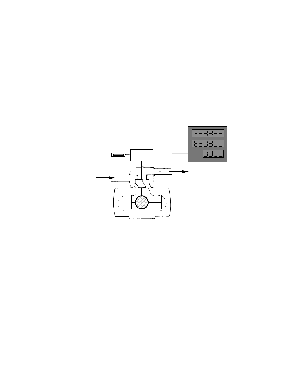
1.1.2 DESCRIPTION
The meter is made up of a body containing four sleeved cylinders which in turn
contain four pistons. These pistons move in connection with two transmission
rods. Rollers connected to a crankshaft move within the groove of these rods.
The alternative linear motion of the pistons therefore results in a rotary crankshaft
movement.
A valve is driven by the crankshaft, successively putting the cylinders in
communication with the meter inlet and outlet. The valve glides between a
slide plate integrated to the body and a gasket fixed to the outlet collector. The
slide plate has four holes, which are connected to the four cylinders. The link
between the gasket and the outlet collector is made via a Teflon diaphragm,
which acts as a seal between intake and exhaust.
The upper section of the crankshaft drives the indicating device.
Pulser
MP T1
Fuel
Entry
Calculator
Fuel
Exit
Meter MA 26
Totaliser
Page 9

Document Ref 903158-001 Page 7
Component Technical Manual MA26 MP-T1 Meter for Fuel Dispensers
Issue A
1.1.3 TECHNICAL SPECIFICATIONS
Characteristics UNITS VALUE
Displacement : Litre 0.700
Maximum flow-rate : l/mn 83
Minimum flow-rate : l/mn 5
Accuracy within the flow range : % ± 0.3
Maximum service pressure : bar 4
Maximum torque during delivery : Nm 4
Pressure drop without torque : bar 0.08 5 l/mn
0.12 40 l/mn
0.15 50 l/mn
0.26 80 l/mn
Adjusting device operating range : % ± 1.1
Environmental Conditions
Climate : marine, tropical, industrial and polar
Ambient temperature range : - 25°C to + 55°C.
Fuel temperature : - 25°C to + 55°C.
Atmosphere : In accordance with climate.
1.1.4 APPROVALS
Metrological
European Approval : 01.00 . 422.003.0 (21 June 2001)
The MA26 meter is a measurement transducer for use in a measuring instrument
for liquids other than water. As such it is tested and certified according to the
OIML (Organisation International de Metrology Legal) Recommendation R1 17.
The certificate is issued under number R117(1995)-NL-01.04 by the NMi (Dutch
national test institute).
Safety
The MA26 meter with the MP-T1 pulser is constructed for use in gasoline
dispensers in a zone 1 area. Therefore the pulser, as an electrical part, has been
approved by LCIE according the European Standard EN 50014 and EN 50018
with protection code EExdIIBT6 with certificate number DEMKO
00.E.128709X.
Page 10

Page 11

Document Ref 903158-001 Page 9
Component Technical Manual MA26 MP-T1 Meter for Fuel Dispensers
1.1.6 METER OPERATION
The fuel enters the meter via the intake orifice (5) and flows up to the valve (3),
where it applies pressure to the piston (7), while the piston (6) linked to the
former by the connecting rod (8) is in communication with the exhaust orifice
via the opening (4) of the rotary valve (3). Both perpendicular pistons that are
linked to the connecting rod (9) operate under the same conditions, offset by
90°.
Inside the connecting rods (8 and 9), two rolls (10) are mounted on the crankshaft
(2). The upper crankshaft pin drives the distribution valve (3) through a peg (1)
located on the crankshaft, transmitting the rotary movement to the indicating
device.
1.1.7 ADJUSTMENT
Capacity can be adjusted by varying the piston stroke. The device contains a
central cam (13) with four ramps, each one acting successively on the four
pistons. Travel can be adjusted by using a lever (11) to turn the cam around its
axle (12). The lever may be positioned firstly in relation to the position of the
cam, via a square section part (14). Its position on the notched part (15) may be
adjusted using the screw (16) which acts as a positioning pin.
The lever is designed in such a way that, whatever its position on the notched
part, the screw (16) is always hidden. It is protected by the sealing device (17).
The clearance needed for adjustment is obtained by the clearance between the
rollers and the connecting rod sliders.
Each notch on the notched part modifies the meter’s cylinder capacity by 0.1%
Access to the adjusting device is made impossible by a seal.
Issue A
Page 12

Page 10 Document Ref 903158-001
MA26 MP-T1 Meter for Fuel Dispensers Component Technical Manual
1.2 MP-T1 Pulser
1.2.1 SYSTEM DESCRIPTION
The MP-T1 pulser is part of the measurement transducer used in a fuel dispenser.
The task of this unit is to detect and to indicate when a volume of 1cl fuel has
left this unit. Below is a short description of the different parts of the
measurement transducer.
This device will be placed in series with the nozzle of a dispenser. It converts
the fuel flow into rotations of a shaft. One rotation of the MA26 volume meter
represents a fuel flow of 70cl.
The MP-T1 housing is placed on top of the volume meter. This housing contains
the MP-T1 electronics (placed on a support), 3 gear wheels and a magnetic
disc. The rotation of the volume meter shaft will be conveyed by the 3 gear
wheels to the magnetic disc. The speed ratio volume meter shaft:magnetic disc
= 1:3.5.
So one turn of the disc represents 20 cl.
The electronic outputs of the MP-T1 pulser, which contain “cl” pulses, will
drive the inputs of the calculator.
One or more pulsers, each with a 4 wire link, are connected to the calculator.
This link contains two pulse lines and two power lines to supply the pulser
1.2.2 FUNCTIONAL PARTITION OF THE MP-T1 ELECTRONICS
The MP-T1 electronics take care of the translation of the magnetic field changes
into proper “cl” pulses needed for the calculator. The MP-T1 electronics can be
divided into the following functional blocks. The functions of the different blocks
are described on the following pages. All digital functions of the MP-T1
electronics are integrated in an Asic.
-
T
backward flow
count
(centilitres)
cl=0
comparator
output
driver
timer
sequence
detector
digital
filter
cl=20+
backward
count
error
Asic parts
forward
count
hall effect sensor (fault detection)
magnetic disc
hall effect sensors (direction)
sensor defect
overflow
not equal
disable
pulse line
A and B
Issue A
Page 13

Document Ref 903158-001 Page 11
Component Technical Manual MA26 MP-T1 Meter for Fuel Dispensers
Magnetic disk
The disc contains one outer ring, divided into 20 north and 20 south polarised
magnetic parts and one inner ring divided into 10 north and 10 south polarised
magnetic parts. The disc will be driven by, as mentioned before, the volume
meter. A liquid flow in forward direction (this liquid has left the measurement
transducer) results in a counter-clockwise movement of the disc. If the liquid is
going backwards the disc will rotate clockwise.
The disc can have small movements in both directions, this will be caused by
vibrations of the MP-T1 pulser. These movements are called “oscillations of
the disc”. The oscillations will never result in centilitre pulses on the output of
the MP-T1 pulser.
Hall effect sensors (direction)
T wo sensors (sensor A and sensor B) are placed above the outer ring of the disc.
They are used to indicate the direction of the disc. Every transition on the
signal coming from sensor B represents a half centilitre.
Hall effect sensor (fault detection)
A third sensor (sensor C) is placed above the inner ring of the disc. Due to the
fact that this ring contains 10 north and 10 south polarised magnetic parts, the
output frequency of this sensor will be the half of the frequency coming from
the two other sensors. This difference in frequency makes it possible to
distinguish between normal operation, sensor defects or disc oscillations.
Digital filter
This part will remove glitches shorter then 8µs from the sensor signals.
Sequence detector
The sequence detector distinguishes the different movements of the disc by
evaluating the three sensor signals.
Backward flow count (centilitres)
When the disc turns clockwise the sequence detector generates backward count
pulses. The backward flow count buffer keeps up with the amount of backwards
count pulses. When the buffer reaches 20 cl (40 pulses) it will generate an
overflow message. If the disc turns counter-clockwise the sequence detector
generates forward count pulses. The backward flow count buffer will decrease
with the amount of forward count pulses until it reaches the 0 cl. At this point
the buffer will not decrease anymore and the switch will be closed so that the
timer receives forward count pulses on its trigger input.
Timer (400µs)
A pulse on the trigger input of the timer will start this one shot 400µs timer.
During this 400µs, the timer will activate the output driver for line A (or B).
Every half cl the timer alternates between line A and B. So, if there was a pulse
on output line A, a half cl later it will be followed by a pulse on output line B.
A pulse on output line B will be followed by a pulse on output line A, etc.
Issue A
Page 14

Page 12 Document Ref 903158-001
MA26 MP-T1 Meter for Fuel Dispensers Component Technical Manual
Output driver
The output driver is necessary to supply the current needed for the inputs of the
calculator. Furthermore it delays the low to high transition of the cl pulses on
the output lines A and B. This delay is to prevent cross talk between the two
pulse lines and interference on other lines.
Comparator
This block checks the input and output of the output driver during the 400µs
pulse. If the output line is high (idle state) while the input of the driver is activated,
it will send a “not equal” signal to the error block.
The inputs of the comparator used for monitoring lines A and B are provided
with a digital filter. This filter will remove glitches (smaller than 32µs) from
these two signals.
Error
The signals “overflow”, “sensor defect” and “not equal” are collected here.
When one or more signals are active, the error signal will be activated. This
signal can only be deactivated by switching off the MP T1 power. When the
error signal is activated, the output driver is disabled, so the output lines become
low (error indication of the MP-T1).
Issue A
Page 15

Document Ref 903158-001 Page 13
Component Technical Manual MA26 MP-T1 Meter for Fuel Dispensers
1.3 MA26 MP-T1 Sealing
1
2
3
4
Piston sealing
A sealing wire feeds through the head of a seal screw fitted in each piston end
cover. This seal wire also diverts upwards between two of the end covers to
feed through a seal screw securing the top housing to the meter body.
The seal wire is drawn taught and a seal fixed for stamp access above the
calibration quadrant.
Pulser sealing
A sealing wire feeds through holes in the bottom right hand corner of the pulser
casting and meter housing, then travels diagonally across the front of the pulser
to pass through either a hole in the meter mounting plate or the head of the front
meter mounting screw.
The seal wire is drawn taught and a seal fixed for stamp access in front of the
pulser.
Calibration sealing
A seal wire passes through holes in the calibration locking screw and is drawn
taught and a seal fixed.
Meter sealing
The meter is sealed into the dispenser by passing a seal wire through the heads
of two of the meter mounting screws.
The seal wire is drawn taught and a seal fixed for stamp access on the top of the
hydraulic stack.
Issue A
Page 16

Page 14 Document Ref 903158-001
MA26 MP-T1 Meter for Fuel Dispensers Component Technical Manual
This page is intentionally blank
Issue A
Page 17

Document Ref 903158-001 Page 15
Component Technical Manual MA26 MP-T1 Meter for Fuel Dispensers
CONTENTS
2. PARTS LIST....................................................................................................................16
2.1 MA 26 Meter ........................................................................................................16
2.2 MA 26 Collector ................................................................................................... 18
2.3 MA26 Bottom Cover ............................................................................................ 19
2.4 MP-T1 Pulser, Gears and Totaliser ....................................................................... 20
Issue A
Page 18

Page 16 Document Ref 903158-001
MA26 MP-T1 Meter for Fuel Dispensers Component Technical Manual
2. PARTS LIST
2.1 MA 26 Meter
Issue A
Page 19

Document Ref 903158-001 Page 17
Component Technical Manual MA26 MP-T1 Meter for Fuel Dispensers
Item Reference Désignation Description
901106 Mes ureur MA 26 as s em blé MA26 meter assembly
1 900015-010 Vi s M6-20 Screw M6-20
2 900050-009 Joint torique 94,5 x 3 O-ring 94,5 x 3
3 900050-010 Joint torique 104,2 x 3 O-ring 104 , 2 x 3
4 900050-011 Joint torique 110 x 3 O-ring 110 x 3
5 900053-002 Vi s torx M6-16 Torx s c re w M 6-16
6 900053-003 Vi s torx M6-20 Torx s c re w M 6-20
7 900101-004 Joint pl at Flat seal
8 900103-002 Circlips Circlips
9 901240 Corps équipé Equipped body
10 901246 Collec teur assembl é Collec t or as s em bly
11 901260 Vilebrequin Crankshaft
901264 Galet Roll
900008-005 Rondell e lai t on Bras s was her
900047-001 Anneau truarc Truarc ring
12 901265 Doigt d’ ent rainement Drive s t ud
13 901266 Tiroir Rotary valve
14 901267 Coulisseau Rod
15 901268 Pl at eau int erne Pi ston dis k
16 901269 Manc het te Piston seal
17 901270 Pl at eau ex t erne Tightening disk
18 901271 Em bas e assemblée Bottom cover ass em bly
19 901277 Couvercle Cover
Issue A
Page 20

Page 18 Document Ref 903158-001
MA26 MP-T1 Meter for Fuel Dispensers Component Technical Manual
2.2 MA 26 Collector
Item Reference Désignation Description
1 900053-001 Vis torx M 4-10 Torx s crew M4-10
2 901247 Collecteur bagué Collec t or wit h bearing
3 901249 Supp. m embrane assem blé (rodé) Counterval ve assem bly (lapped)
4 901251 Joint profil S vert Lipseal (green vi ton)
5 901252 Rondelle lai ton Bras s was her
6 901256 Ressort Spring
7 901257 Joint pl at Flat seal
Issue A
Page 21

Document Ref 903158-001 Page 19
Component Technical Manual MA26 MP-T1 Meter for Fuel Dispensers
2.3 MA26 Bottom Cover
Item Reference Désignation Description
1 900017-004 Vis CHc M8-50 i nox CHc st ainles s st eel screw M8 -50
2 900050-003 Joint torique 13, 6 x 2,7 O-ring 13.6 x 2.7
3 900101-005 Joint p l at F lat seal
4 901272 E m base Bot tom c over
5 901273 Came Adj ustmen t cam
6 901274 Levier de réglage Adjus tment lever
7 901275 V i s de plombage Seali ng screw
8 901276 Cage de pl om bage Seal housing
Issue A
Page 22

Page 20 Document Ref 903158-001
MA26 MP-T1 Meter for Fuel Dispensers Component Technical Manual
2.4 MP-T1 Pulser, Gears and Totaliser
6
Issue A
Item Reference Désigna tion Description
1 900643-001 V i s Fhc M 6 x 12 i nox Sc rew M6-12 s tainless st eel
2 901280 Pignon - vis d’entrai nem ent Endles s sc rew wheel
3 901281 Pignon axe intermédi aire Intermediat e s haft gear
4 901283 Pignon ent raîneur émetteur Puls er drive wheel
5 901284 Support t otalis at eur équipé Totaliser support as sembly
6 900843 Emetteur MP T1 avec câble MP-T1 pulser wit h c abl e
900743-002 Totalisateur mec ani que Mec hanical Totalis er
900043-001 E crou serrures pour tot al i s at eur Lock i ng nut for tot al i s er M 10x 1.00
Page 23

Document Ref 903158-001 Page 21
Component Technical Manual MA26 MP-T1 Meter for Fuel Dispensers
CONTENTS
3 TROUBLE SHOOTING ................................................................................................22
3.1 Piston Meter Blocked ...........................................................................................22
3.2 Calibration Error ...................................................................................................23
3.3 External Leakage .................................................................................................. 23
Issue A
Page 24

Page 22 Document Ref 903158-001
MA26 MP-T1 Meter for Fuel Dispensers Component Technical Manual
3 TROUBLE SHOOTING
3.1 Piston Meter Blocked
Meter inlet
pressure
OK?
NO
NO
YES
YES
Meter outlet
line open?
❍ Check the pump
❍ Check the nozzle
❍ Check the solenoid
valves
❍ Mechanism damaged
Issue A
Page 25

Document Ref 903158-001 Page 23
Component Technical Manual MA26 MP-T1 Meter for Fuel Dispensers
3.2 Calibration error
Positive display error / not enough liquid in the can:
❍
❍❍
❍ External leakage
Adjust the meter (see section 1.1.7)
Negative display error / Too much liquid in the can.
❍
❍❍
❍ Adjusting cam damage
If low flow error higher than max flow error over 0.5 %:
❍
❍❍
❍ Internal leakage through :
-piston seals
-diaphragm
-rotary valve
100.90
100.80
100.70
100.60
100.50
100.40
100.30
100.20
100.10
100%
99.90
99.80
99.70
99.60
99.50
99.40
99.30
99.20
99.10
3.3 External Leakage
Leakage : ❍...through the drive shaft: lip seal faulty
❍...under the collector : collector O-ring faulty
❍...under a cover: cover O-ring faulty
❍...through the adjustment axle: adjustment axle O-ring faulty
❍...under the bottom cover : bottom cover O-ring faulty
Issue A
Page 26

Page 24 Document Ref 903158-001
MA26 MP-T1 Meter for Fuel Dispensers Component Technical Manual
This page is intentionally blank
Issue A
Page 27

Document Ref 903158-001
Component Technical Manual MA26 MP-T1 Meter for Fuel Dispensers
This page is intentionally blank
Issue A
Page 28

Tokheim Europe & Africa Headquarters
ZAC Paris Nord 2
B.P. 40027 Tremblay-en-France
95912 Roissy C.D.G. Cedex
France
! +33 (0)1 49 90 77 00
" +33 (0)1 49 90 77 77
# marcom@tremblay.tokheim.com
Manufacturing
Unit 3, Baker Road
West Pitkerro Industrial Estate
Dundee DD5 3RT
Scotland
! +44 (0)1382 598000
" +44 (0)1382 598001
# service@tokheimuk.com
F
GB
SALES & SERVICE DIVISIONS - EUROPE
Austria
Tokheim
Eitzenberger Straße 4-6
A-2544 Leobersdorf
! +43 (0) 2256 606 0
" +43 (0) 2256 606 170
# office@leobersdorf.tokheim.com
Belgium
Tokheim
Everdongenlaan 31
2300 Turnhout
! +32 (0) 14 44 85 00
" +32 (0) 14 44 85 55
# saelen@turnhout.tokheim.com
Czech Republic
Tokheim
Pernerova 48
CZ-18602 Prague 8
! +420 2 248 90312
" +420 2 232 72 67
# pribrsky@prague.tokheim.com
Denmark & Scandinavia
Tokheim Scandinavia
Hejrevang 10
3450 Allerød
! +45 48 13 45 45
" +45 48 17 45 96
# service@alleroed.tokheim.com
France
Tokheim Services France
9 Avenue Galilée
92350 Le Plessis-Robinson
! +33 (0)1 41 36 13 00
" +33 (0)1 41 36 13 70
# parise@plessis.tokheim.com
Tokheim Sofitam Applications
ZAC Paris Nord 2
B.P. 40027 Tremblay-en-France
95912 Roissy C.D.G. Cedex
! +33 (0)1 49 90 77 00
" +33 (0)1 49 90 77 77
# accueil-tremblay@tremblay.tokheim.com
Germany
Tokheim GmbH
Lothstrasse 1a
D-80335 München
! +49 (0) 89 189 530
" +49 (0) 89 189 533 99
# service@muenchen.tokheim.com
Italy
Tokheim Sofitam Italia S.r.l.
S.P. 26 Km 10 800
14030 Scurzolengo (AT)
! +39 0141 2038200
" +39 0141 2038222
# info@asti.tokheim.com
Netherlands
Tokheim Netherlands B.V.
Touwslagerstraat 17
Postbus 4186
2980 GD Ridderkerk
! +31(0) 180 48 15 00
" +31(0) 180 48 15 55
# sales@ridderkerk.tokheim.com
Poland
Pol-Germann Tokheim Sp. z.o.o.
UL. Narwicka 1
PL-80-557 Gdansk
! +48 58 343 21 71
" +48 58 343 22 15
# plgerma@softel.gda.pl
Portugal
G.N.C.
Parque de Ciencia e Tecnologia
Edificio Tecnologia 1, N° 27
2780-920 Oeiras
Lisboa
! +351 214 220 420
" +351 214 214 226
Russia
Tokheim Russia & CIS
50, Office 603-605, Zemlyanoy Val St.
Moscow, 109544 GSP
! +7 095 916 6879
" +7 095 916 6878
# kolobov@dol.ru
Slovak Republic
Tokheim
Mlynske Nivy 70
SK-82015 Bratislava
! +421 2 58 27 02 15
" +421 2 52 41 41 23
# schroeder@berlin.tokheim.com
Spain
Koppens Iberica
Calle Imprenta 5
Poligono Industrial de Alcobendas
28100 Alcobendas (Madrid)
! +34 91 661 28 13
" +34 91 661 41 30
# urra@madrid.tokheim.com
Switzerland
Tokheim
Route du Crochet 7
Case Postale 50
1762 Givisiez
! +41 (0)26 460 51 11
" +41 (0)26 460 51 12
# user@givisiez.tokheim.com
United Kingdom
Tokheim
Adur Boatyard, Old Shoreham Road
Shoreham-By-Sea
West Sussex BN43 5TA
! +44 (0)1273 454831
" +44 (0)1273 464863
# sales@tokheimuk.com
AFRICA
Export Division
ZAC Paris Nord 2
B.P. 40027 Tremblay-en-France
95912 Roissy C.D.G. Cedex
France
! +33 (0)1 49 90 77 56
" +33 (0)1 49 90 77 93
# marcom@tremblay.tokheim.com
Cameroon
Socatam S.A.
BP 3941
Douala
! +237 40 57 86
" +237 40 57 88
# socatam.douala@camnet.cm
Morocco
Matam S.A
209 Bld Moulay Ismail
Route de Rabat
Casablanca
! +212 22 40 40 24
" +212 22 40 40 21
# matam@wanadoo.net.ma
Senegal
Cosetam S.A.
Quartier de Bel Air
Route des Hydrocarbures
BP 1237
Dakar
! +221 832 23 71
" +221 832 68 34
# cosetam@ns.arc.sn
South Africa
Tokheim South Africa Ltd
Stand 110, Precision Road
Kya Sand, Randburg
! +27 11 462 2105
" +27 11 462 1942
# tokheimsales@tokheim.co.za
Tunisia
Cottam SARL
116 Ave de l’Union du Maghreb Arabe
BP 117
La Soukra
2036 Tunis
! +216 175 95 50
" +216 175 95 30
# cottam@planet.tn
As Tokheim regularly improves its
products to ever better respond to
evolving market and regulatory requirements, it reserves the right to
change any of the specifications of
these products, and this without prior
notice.
B
A
B
CZ
F
F
I
MA
ZA
TN
DK
SK
CH
NL
P
GB
E
F
SN
D
PL
RUS
RFC
 Loading...