

Page 1
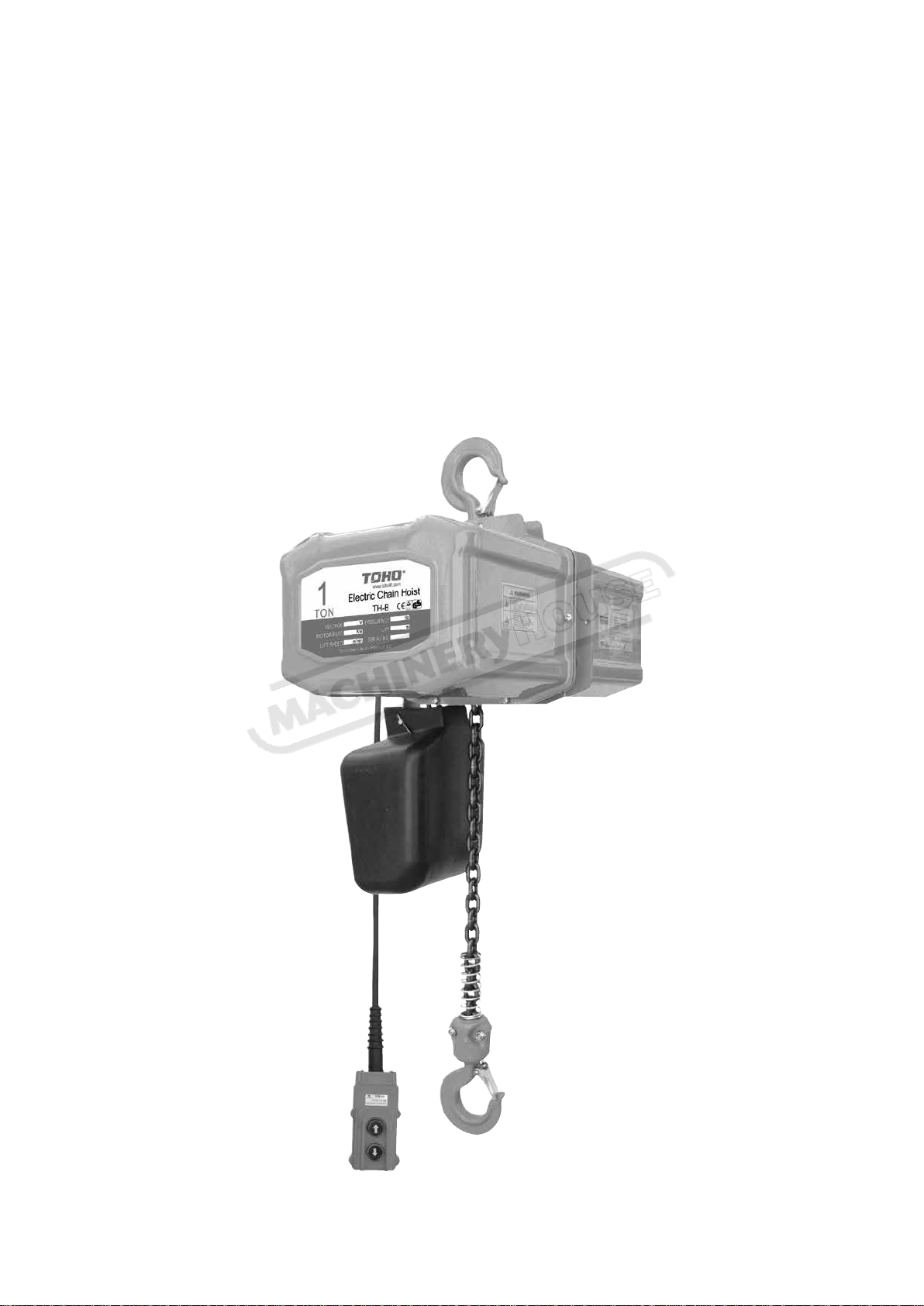
INSTRUCTION MANUAL
02/08/2019
Instructions Manual for TECH0106 (H251)
1
TECH0106
Electric Chain Hoist
1 Tonne x 6 Metre Lift
H251
Page 2
WARNING
This hoist should not be installed, operated or maintained by any person who has
not read all the contents of these general instructions. Failure to read and comply
with these instructions or any one of the limitations noted herein can result in
injury and/or property damage.
02/08/2019
Instructions Manual for TECH0106 (H251)
2
TECH- SERIES 240V ELECTRIC CHAIN HOIST
(Capacity 1T & 2T)
OPERATING INSTRUCTIONS
Page 3
1
02/08/2019
Instructions Manual for TECH0106 (H251)
3
1、Warning
a) Ensure the hoist has correct earth connection before operation.
b) Before lifting a load, examine the load chain to ensure that there is no twist, kink, and
no turn-over of bottom hook for multi-falls.
c) The hoist is only used for load within capacity, any application for over rated capacity
is forbidden.
d) Ensure to lift a load vertically, diagonal lift or tow a load is not allowed beyond
10degree.
e) While operating, personnel are prohibited to stand or work underneath the load.
f) Do not lift any load with the load chain acting as a sling.
g) Never apply any load to the tip of hook for lifting.
h) While lifting, do not operate the hoist rapidly up and down & repetitively.
i) Don’t run the hoist out of the limit position.
j) Never lift a load using 2 or more than 2 hoists simultaneously.
k) Don not dismantle and adjust the limit load device.
l) Measuring the load by load limit device is forbidden.
m) The load chain should be properly lubricated with suitable oil or grease before applied
to lifting purpose, and periodic lubrication is necessary in normal operation.
n) When lifting, the slings should be properly put into the hook throat with the safety latch
properly closed.
2、Application
TECH series electric chain hoist is based on Japanese and Germany technology with the
features of compact structure, light weight, easily operation with load limit and thermal
protection. The hoist is widely used in factories, workshops, mines, ports, warehouses etc,
and can be used together with cranes as an integral part of an overhead craning system,
serving as a highly efficient method of operation.
3、Features
1) Safe and reliable
a) Brake: adopting D.C. normal close brake, without asbestos. Once the motor
stops, the brake can hold the load safely and continually .
b) This hoist is equipped with an electronic limit load device, which prevents chain
failure and stretching.
c) Friction clutch: prevents motor damage due to overloading and chain stretching.
d) The motor is equipped with a thermal protection device, which preventing the
motor being damaged due to overheating.
e) Top and bottom hooks are made of high tensile alloy steel with special heat
treatment. It prevents the hook from breaking and being deformed gradually
under a sudden extra-load.
f) Load chain is carbonized to ensure good wear and long life.
g) Chain container serves as a storage bag, keeping the load chain clear of dirt and
dust, and without tangles while falling down freely.
Page 4
1t
下
上
Item NO.
TECH0103
TECH0106
TECH0203
TECH0206
Rated Load (ton)
1 1 2 2 Standard Lift (m)
3 6 2 6 Lifting Speed (m/min)
6 6 3 2 Output (kw)
1.2
1.2
1.2
1.2
Power Supply
240v 50HZ Single Phase
INS Class
F
%ED
40%
Dimension of Load chain
7.1mmX 21mm
Strands of Load chain
1 1 2 2 Test load (ton)
1.25
1.25
2.5
2.5
Cable Length(m)
2.5
2.5
2.5
2.5
Net Weight (kg)
58
62
63
70
Extra weight per meter of extra
lift (kg)
1.1
1.1
2.2
2.2
Minimum headroom (mm)
520
520
630
630
Main dimensions
A (mm)
245
245
245
245
B (mm)
245
245
245
245
C (mm)
158
158
124
124
D (mm)
142
142
176
176
E (mm)
350
350
350
350
F (mm)
600
600
610
610
02/08/2019
Instructions Manual for TECH0106 (H251)
4
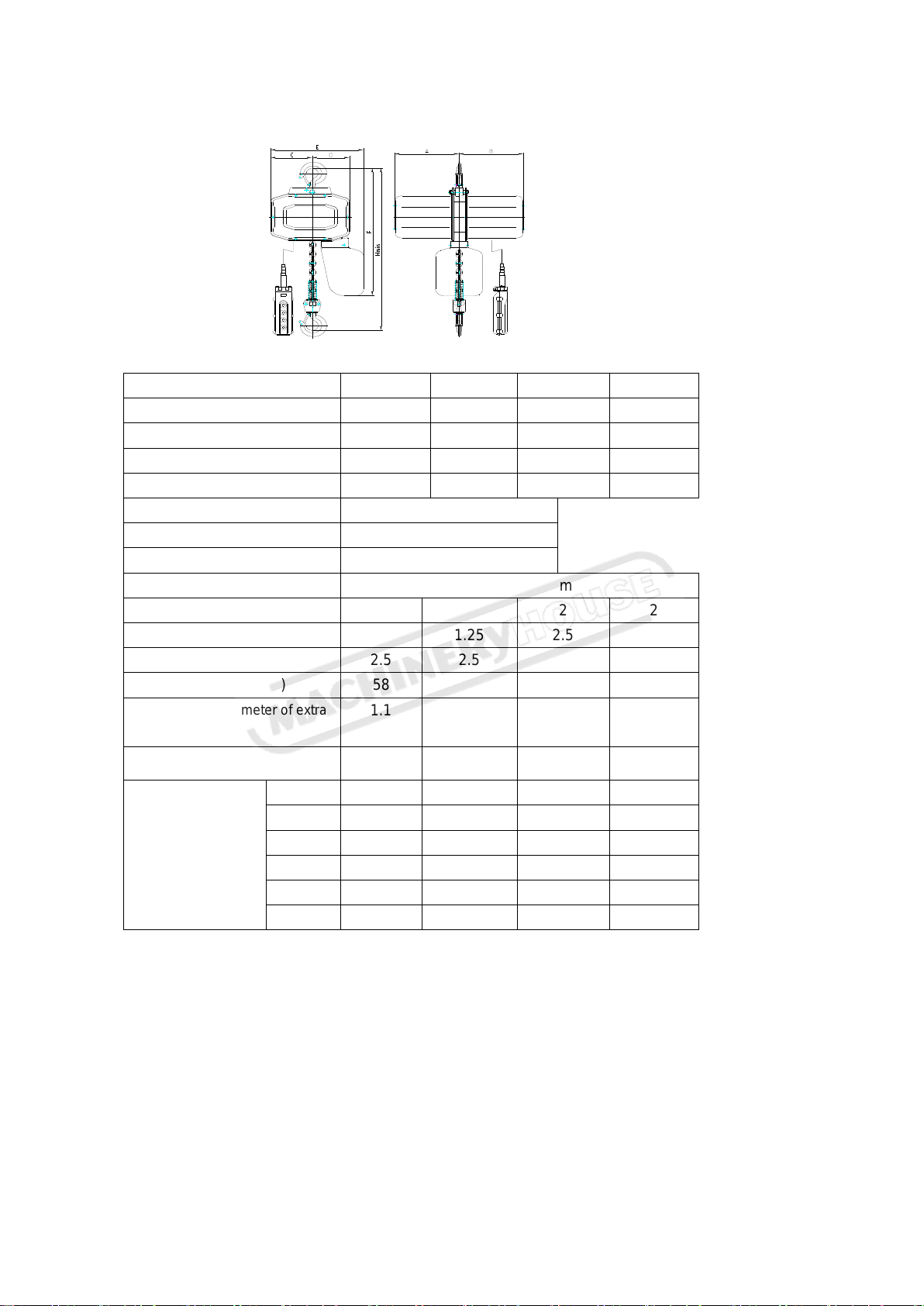
4、Dimension & Specification
5、Technical Specification:
1) Relative humidity: <85%
2) Ambient temperature: -25ºC-40ºC
3) Working class: M4
4) Level of Protection: IP54
5) Main power: 1P/240V/50HZ
6) Chain size: φ7.1X 21
7) The hoist can not be used in a flammable, explosive or corrosive environment.
Page 5
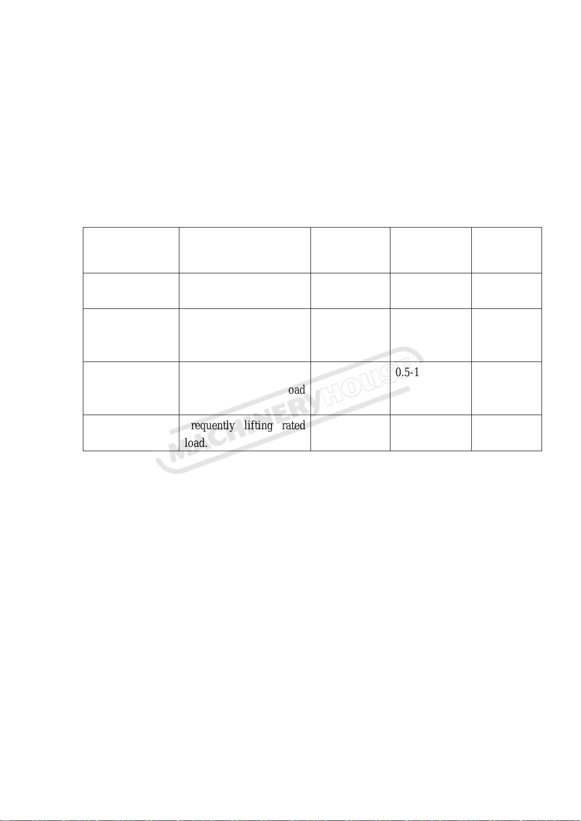
Load cond.
Explanation
Load spectrum
factor
Daily operating
time (h)
Total
operating time
(h)
1, Light load
Seldom lifting rated load,
generally for light lifting
0.125
2-4
6400
2, Medium
Sometimes lift rated
load, generally lift.
Medium Load.
0.25
1-2
3200
3, Heavy
Often lift rated load,
generally for heavy load
lifting.
0.5
0.5-1
1600
4, Extra heavy
Frequently lifting rated
load.
1.0
0.25-0.5
800
02/08/2019
Instructions Manual for TECH0106 (H251)
5
6、Duty Cycle
The hoist is not designed for continuous all day usage and has a recommended duty cycle.
Please refer to the table below to ensure a long and safe life for this product.
( table 3-1)
Table 3-1
7、Installation instruction
1) Installation and test operating
a) When TECH series is ready to install, install the hoist to a rated support structure,
switch it on as the nameplate indicates, and push the pendant button to watch for the
running direction of load hook,
b) Before operating a new hoist for its first lifting, it should be operated without load
for a full cycle to ensure the correct and smooth running. The same procedure should
be given to a hoist which has been out of usage for a long time.
2) Maintenance
Maintenance should be effected byqualified personnel every year, and great
attention paid to the below parts and components.
a) Load chain: with daily service, the chain should be always oiled or lubricated by
grease, in the meantime, a periodically inspection for abrasion is needed. Refer to
the illustration figure for the inspection, if any one of the measurements in the
following table are exceeded, the chain must be replaced.
b) Brake device: Maintenance inspection every three months, the brake should be
Page 6
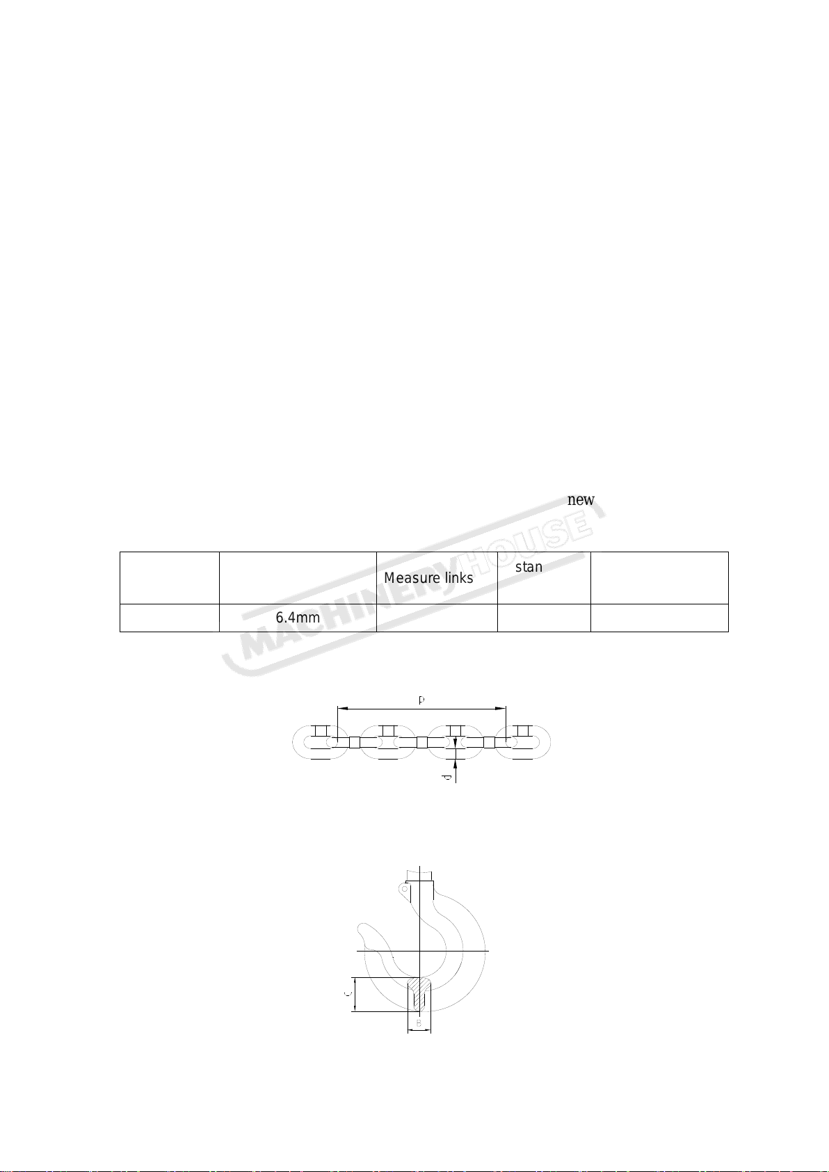
Dia. of chain
(d)
Wearing Limit value
(d)
Measure links
standard
value (p)
Wearing Limit
value (p)
7.1mm
6.4mm
5
106mm
109.2mm
4
02/08/2019
Instructions Manual for TECH0106 (H251)
6
cleaned to ensure it is clear of dust and oil, also, inspect the working space of the
brake device, if abrasion (wear) of the brake disc is more than the maximum
working space (1mm), then the working space should be adjusted and if abrasion
of friction disc is near to the aluminum core, the brake disc should be replaced ,
otherwise, the brake device will be damaged.
c) Gearing: cleaned and greased (i.e.no.1) every year.
d) Bearing: cleaned and greased (i.e.no.1) every year.
e) Hooks: to be checked periodically for deformation and wear, if the wear or
deformation measures a reduction of 10% or greater of the standard sizes (ref to
illustrated figure), replace the hooks.
f)
3) Repair
There are no user serviceable parts inside hoist. Covers should only be removed by
qualified service personnel..
8) Illustration figure for chain inspection
If chain is worn over the limit value, it must be replaced with a new one.
5) Illustration figure for hook inspection
If the size “b” and “c” is smaller than the 90% of the standard size, please replace with new one.
Page 7
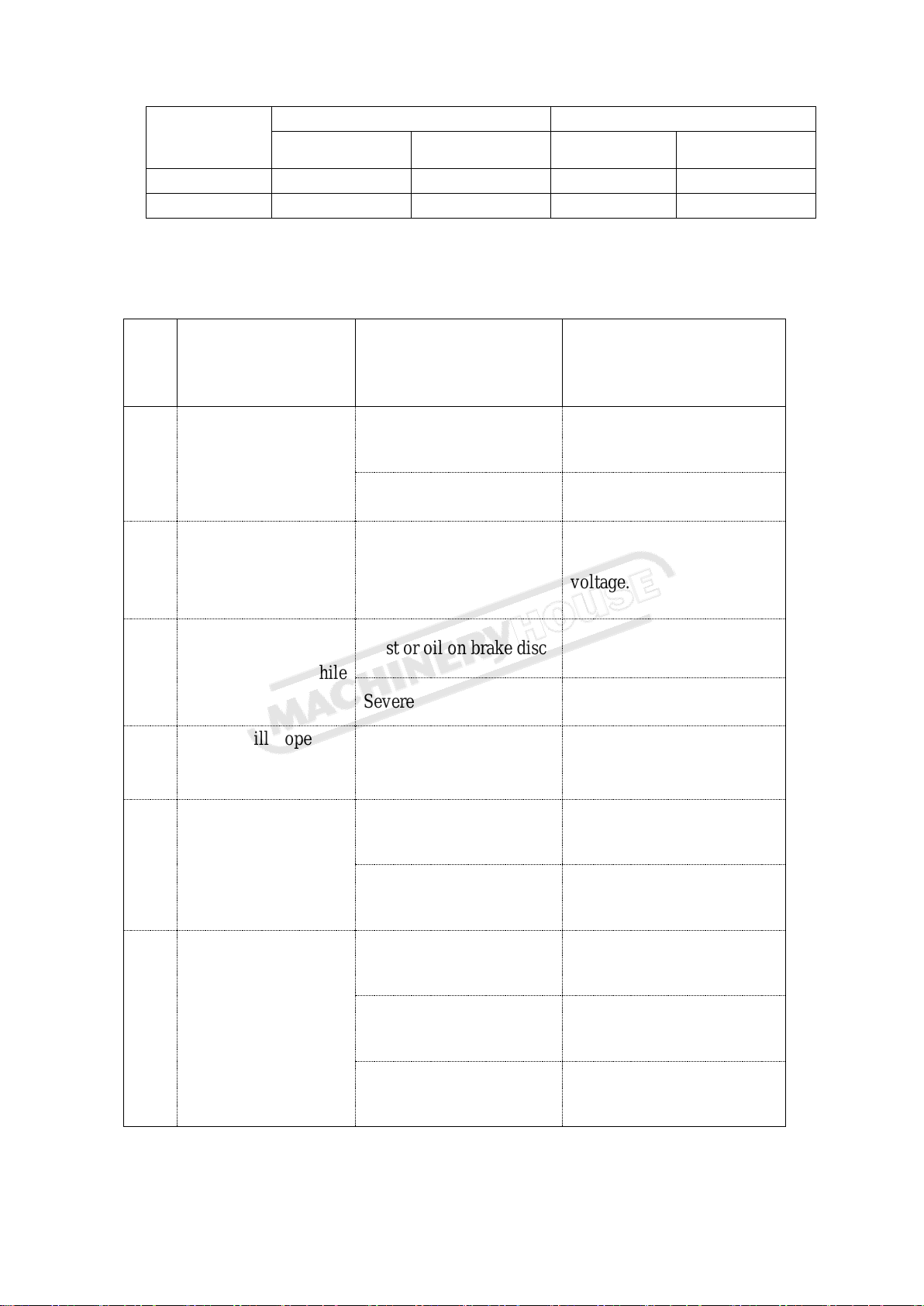
capacity (t)
B (mm)
C (mm)
Normal Size
Abnormal Size
Normal Size
Abnormal Size
1
19.5
17.5
27
24.3
2
22
19.8
32
28.8
NO.
Condition
Causes
Check
1
The hoist fails to
operate when switched
on
Power cable not
connected or loose
Check and fasten all the
cable connection points.
Electrical parts damaged
Replace the damaged part
2
Hoist refuses to
operate, and the
brake parts emit a
buzzing noise.
Voltage is too low.
Operate under rated
voltage.
3
After switching off,
the load drops while
braked
Dust or oil on brake disc
Clean the disc
Severe wear of disc
Replace the disc
4
Hoist still operates
when the control
button is released
The contactor is
damaged or faulty.
Replace contactor
5
Excessive chain
noise when running
The chain is not
lubricated properly
Lubricate chain by oil or
grease
The chain or sprocket
wheel is worn
Replace.
6
Voltage leakage
The earth connection is
faulty
Ensure good earth
connection
High humidity in the air
Improve the environment
Dust on the electrical
parts
Keep the parts clear of dust
5
02/08/2019
Instructions Manual for TECH0106 (H251)
7
8、Fault finding
Page 8
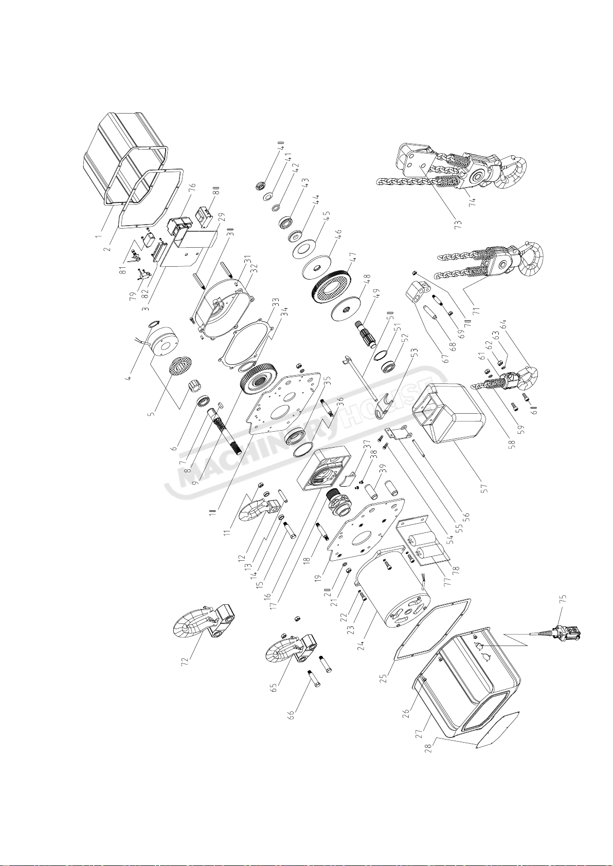
9、 EXPLODED DRAWING
6
02/08/2019
Instructions Manual for TECH0106 (H251)
8
Page 9
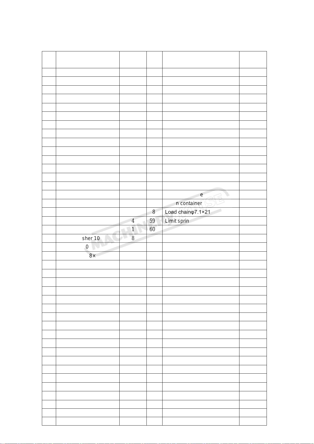
No. Part name
Quantity
NO.
Part name
Quantity
2
Cover A
1
42
Nut washer
1
2
Motor cover packing
1
43
Rolling bearing 6004Z
1
3
Electric board
1
44
Spring set
1
4
Axle race 25
1
45
Spring
1
5
Brake assembly
1
46
Friction disk pressing panel
1
6
Rolling bearing 6005Z
1
47
Washer A
1
7
Pinion gear A
1
48
Limit device base
1
8
Flat key 8×7×20
1
49
Pinion B
1
9
Master gear B
1
50
Limiter rotating axle
1
10
Right side plate
1
51
Stop ring 47
1
11
Hex nut M10
10
52
Rolling bearing 6204ZN
1
12
Top hook
1
53
Limiter baffle
1
13
Hook holder stop lever
1
54
Screw M6×16
2
14
Hook axle washer
2
55
Chain container hanging plate
1
15
Hook axle
1
56
Connecting pole
1
16
Chain container
1
57
Chain container
1
17
Chain sprocket
1
58
Load chainφ7.1×21
1
18
Staying pole
4
59
Limit spring
2
19
Left side plate
1
60
Hex bolt M8×30
2
20
Spring washer 10
8
61
Bottom hook assembly
2
21
Hex nut M10
8
62
Hex nut M8
2
22
Hex screw M8×20
4
63
Spring washer 8
2
23
Hex screw M8×20
4
64
Bottom hook
1
24
Motor assembly
1
65
Top hook assembly(2t)
1
25
Motor cover packing
1
66
Hook axle (2t)
2
26
Screw M6×8
12
67
Chain suspension holder (2t)
1
27
Cover B
1
68
Connecting pin(2t)
1
28
Name plate
2
69
Pin (2t)
1
29
Rivet screw
2
70
Hex nut M8(2t)
2
30
Hex screw M6×20
4
71
Bottom hook assembly (2t)
1
31
Spring locating pin 6×16
2
72
Top hook assembly(3t)
1
32
Gear case
1
73
Top pulley assembly (3t)
1
33
Gear case space
1
74
Bottom hook assembly (3t)
1
34
Axle race 42
1
75
Push button
1
35
Rolling bearing 6009ZN
1
76
contactor
3
36
Stop ring 75
1
77
Run capacitor(30μF)
1
37
Load chain baffle
1
78
Start capacitor(170μF)
1
38
Screw M6×10
2
79
Limit switch
2
39
Conduit
2
80
transformer
1
40
Nut M20×1.5
1
81
rectifier
1
41
Stop washer 20
1
82
Amphenol connector
1
7
02/08/2019
Instructions Manual for TECH0106 (H251)
9
10、Parts List
Page 10
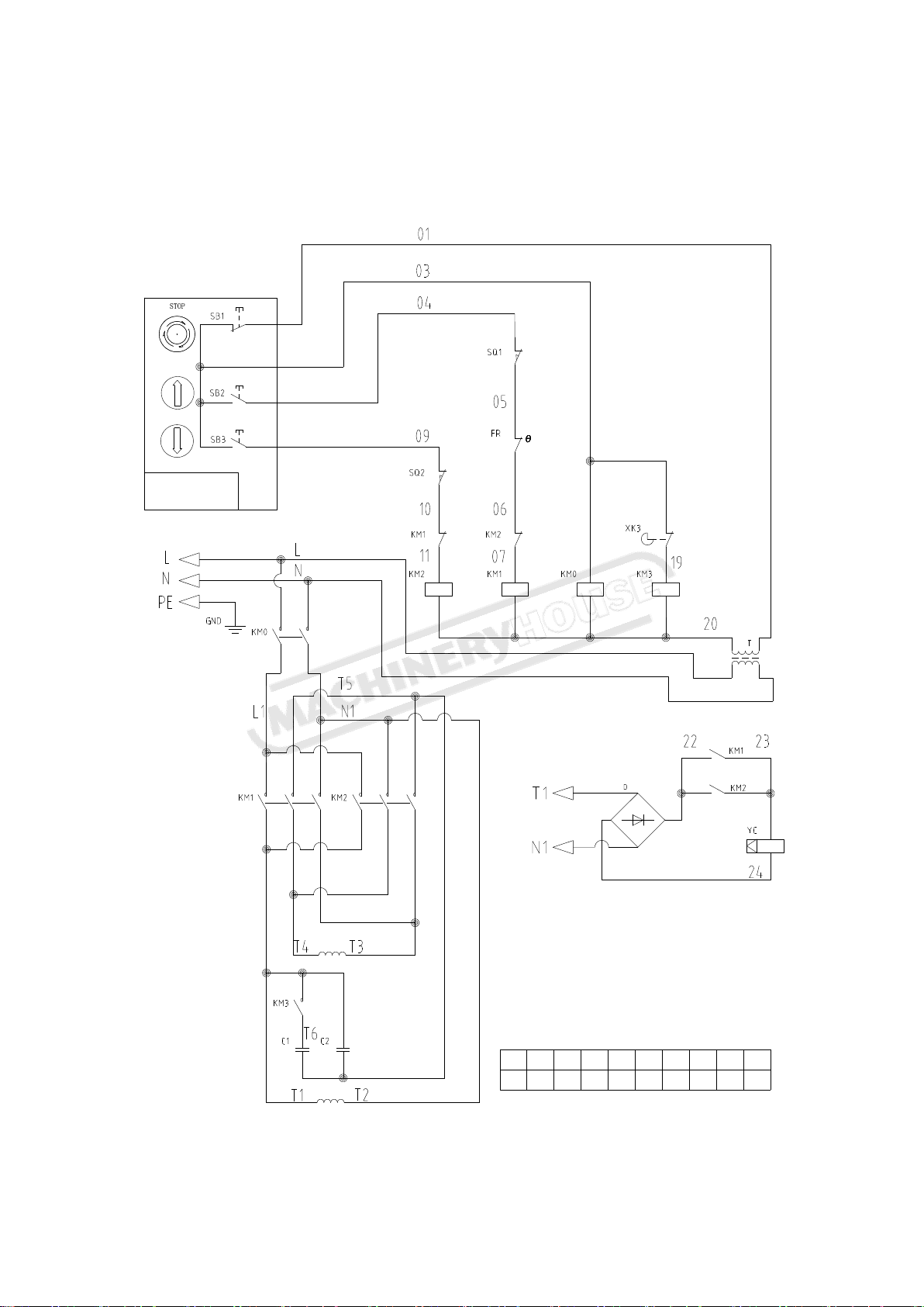
8
XT
L1N 01 03 04 09 T1 T2 T3 T4
2 3 4 5 6 7 8 109
UP
DN
24V/AC
Push-button switch
02/08/2019
Instructions Manual for TECH0106 (H251)
10
11、ELECTRICAL DRAWING
 Loading...