

TOHATSU VF53AS, VF63AS-R Owner's Manual
TOHATSU PORTABLE FIRE PUMPS
OWNER’S MANUAL
Model
VF53AS, VF63AS-R
Original instructions
TOHATSU CORPORATION
Date of print:(2018.02)
Date of publication:(2018.02)
003-12076-0 AH1

Copyright@2016 Tohatsu Corporation. All rights reserved. No part of this
manual may be reported or transmitted in any from or by any means
without the express written permission of Tohatsu Corporation.

APPLICATIONS OF THIS FIRE PUMP
USAGE
TOHATSU portable fire pump ” VF53AS and VF63AS-R” are manufactured
for use in fire fighting operations.
The portable fire pumps are intended only for fire fighting activities in
collaboration with general public fire extinguishing equipment.
Using it for other applications is regarded as being used for improper
purposes.
The manufacturer of the fire pump bears no responsibility for any damages
that may result from modification of the fire pump without prior permission
from the manufacture, improper use of the fire pump, or use of the fire pump
for applications other than those stated above.
Note that use the fire pump for applications other than those stated above
can result in personal injury or damage to the equipment.
Using the fire pump within the range of intended uses implies that the user
should follow the instructions provided by the manufacturer relevant to
operation, servicing and maintenance.
Intended people
All persons who operate, service or maintain the fire pump must read and
understand the following items:
・Owner’s manual
・Safety-related instructions on the pump and the other parts such as a
battery.
・The other owner’s manuals, such as a battery charger.
The portable fire pump should be operated by only persons who received
training as operators of fire engines along with each country’s (region’s)
regulations.
The range of personal responsibility and supervision must be strictly defined
by the user.
If a person does not have adequate professional knowledge which is
required for his/her assignment, he/she must undergo relevant training or
receive appropriate instructions from an individual who is actually
knowledgeable in operation of the fire pump.
A person who does not have enough knowledge is not permitted to operate
the fire pump.
When using the fire pump, conditions under which an explosion may occur
are not considered.
Keep the manual in a safe place for further reference.
CAUTION
・
・
Operators of the fire pump must always refer to all the
relevant manuals in order to avoid errors, personal
injuries and equipment damages when operating the
portable fire pump, and to maintain faultless operation.
Place owner’s manual so that operators can refer to it
・
where they operate the fire pump.

INTRODUCTION
Thank you for purchasing the TOHATSU Fire Pump.
This fire pump has passed a range of quality assurance standards.
Owner’s manual
The portable fire pump complies with relevant laws and regulations.
The manual includes descriptions for operation and maintenance. Before
using the fire pump, be sure to read and understand the manual thoroughly.
Engine operation
The manual also includes descriptions for operation and maintenance of the
engine.
NOTE
・The manual is an important item that goes with your portable
fire pump.
・ The manual should accompany the fire pump if sold to
another person
.
MANUFACTURER AND AFTER-SALES SERVICE ADDRESS
Before using the fire pump, write down the serial number in the following
boxes. This will be useful when you inquire about servicing, repairs, or
genuine parts.
TOHATSU CORPORATION
Address : 3-5-4 Azusawa, Itabashi-ku, Tokyo, JAPAN
FAX : +81-3-3966-2951
Phone : +81-3-3966-3137
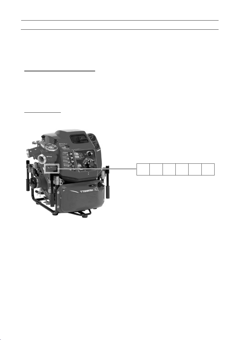
Serial Number
(Identification Number)
The pump identification
number is marked on the
adapter discharge valve.
GENERAL SAFETY INFORMATION
Overview
Before operating the TOHATSU fire pump
thoroughly read the manual. Understanding
proper operating procedures including
“DANGER”, “WARNING”, “CAUTION” and
“NOTE”. These notices are designed to bring
attention to very important information
necessary to ensure safe, trouble free
operation.
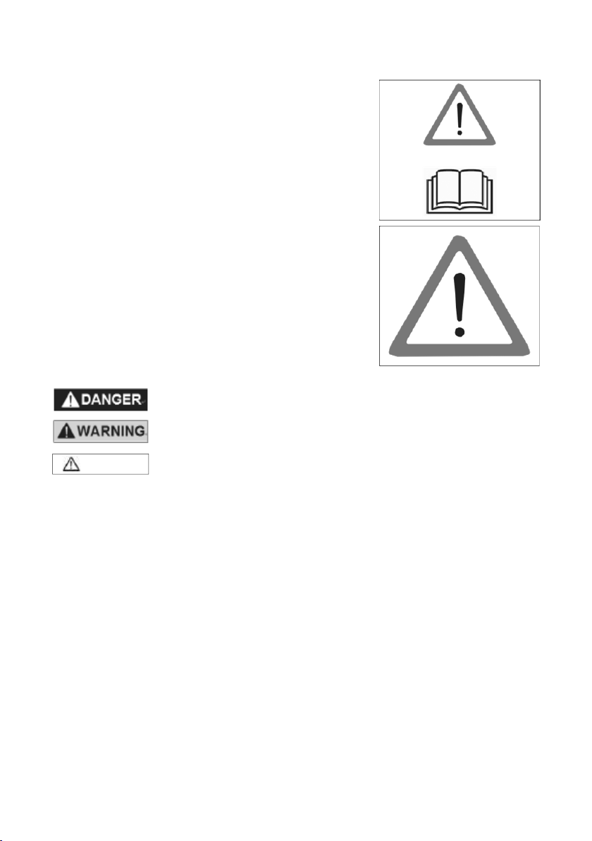
Warning sign meaning
This sign is used for safety-related
instructions in this manual.
Be sure to follow all safety-related instructions,
otherwise personal injury may occur.
Signal words
CAUTION
・ The instruction provides special information to facilitate the use or
maintenance of the pump or to clarify important points.
・For attaching position of the warning label, refer to the contents “3
LABELS”.
・Warning labels should be read clearly at any time.
If the display of the warning label may become difficult to be read, it
was almost come off, you must replace paste immediately.
Safety-related instructions and warning signs
Failure to observe will result in severe personal injury
or death, and possibly property damage.
Failure to observe could result in severe personal injury
or death.
Failure to observe could result in personal injury or
property damage.
Read and follow the safety-related instructions described in the manual and
all warning signs on the portable fire pump thoroughly.
Always keep the warning signs in a legible condition. If any warning sign
becomes illegible or detached, replace it immediately.

Transporting the portable fire pump
・
CAUTION
Retractable handle is folding
type.
・
Do not put a hand or finger
between top of th e retractable
handle and bracket.
・
When transporting the portable
fire pump, assign one person per
handle.
・
Also, transporting the portable fire pump, it should be
transported holding the handle firmly. There is a risk of
injury to the leg by fall.
Durability of protection
When you purchase a new pump, it is placed in a packing box
and protected.
Storage of pump after transportation
Keep the pump away from high humidity, and place it on a horizontal plane.
Disposal of packing box
Dispose the packing box by following the
environmental laws.
Wear proper hearing protection
CAUTION
・
during operation.
Exhaust gas
Exhaust gas emitted from the engine contains carbon
monoxide (CO) etc. that may seriously affect human health.
Do not operate the engine in a room, car, warehouse, tunnel
or other closed locations that have poor ventilation.
Mortal danger due to carbon monoxide (CO) poisoning.
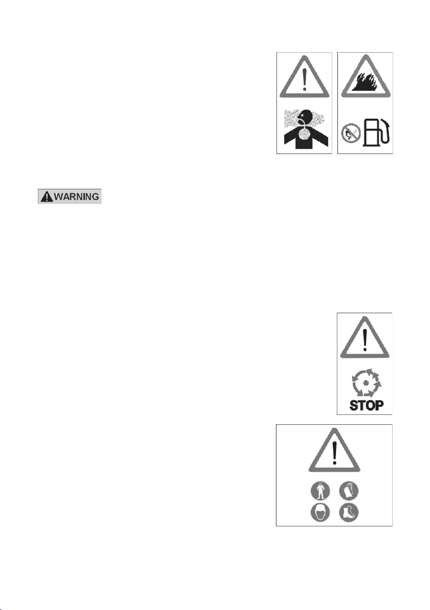
Handling of fuel
Exercise care when handling fuel. Failure to do
so may cause fire.
Do not bring any flames near fuel.
Stop the engine before refilling fuel.
Do not smoke while refilling fuel.
Do not refill fuel in an enclosed room to avoid
an explosion by fuel fumes.
If fuel spills, wipe it with a cloth or other material, and dispose it according to
relevant laws and regulations.
・Crude oil, gasoline, diesel fuel and other petroleum products
can expose you to chemicals including toluene and benzene,
which are known to the State of California to cause cancer
and birth defects or other reproductive harm. These
exposures can occur in and around oil fields, refineries,
chemical plants, transport and storage operations such as
pipelines, marine terminals, tank trucks and other facilities and
equipment. For more information go to:
www.P65Warnings.ca.gov/petroleum.
Safety devices
Before operating the portable fire pump, be sure to check
that all the safety devices have been installed in the
appropriate positions.
Before removing the safety devices, turn the main switch off.
Protective clothing and Protective equipment
During fire extinguishing training or regular fire
fighting
services, wear normal protective
clothing and equipment to protect your
body.
・Fire protective closing
・Fireproof helmet
・Fireproof protective gloves
・Fireproof protective boots
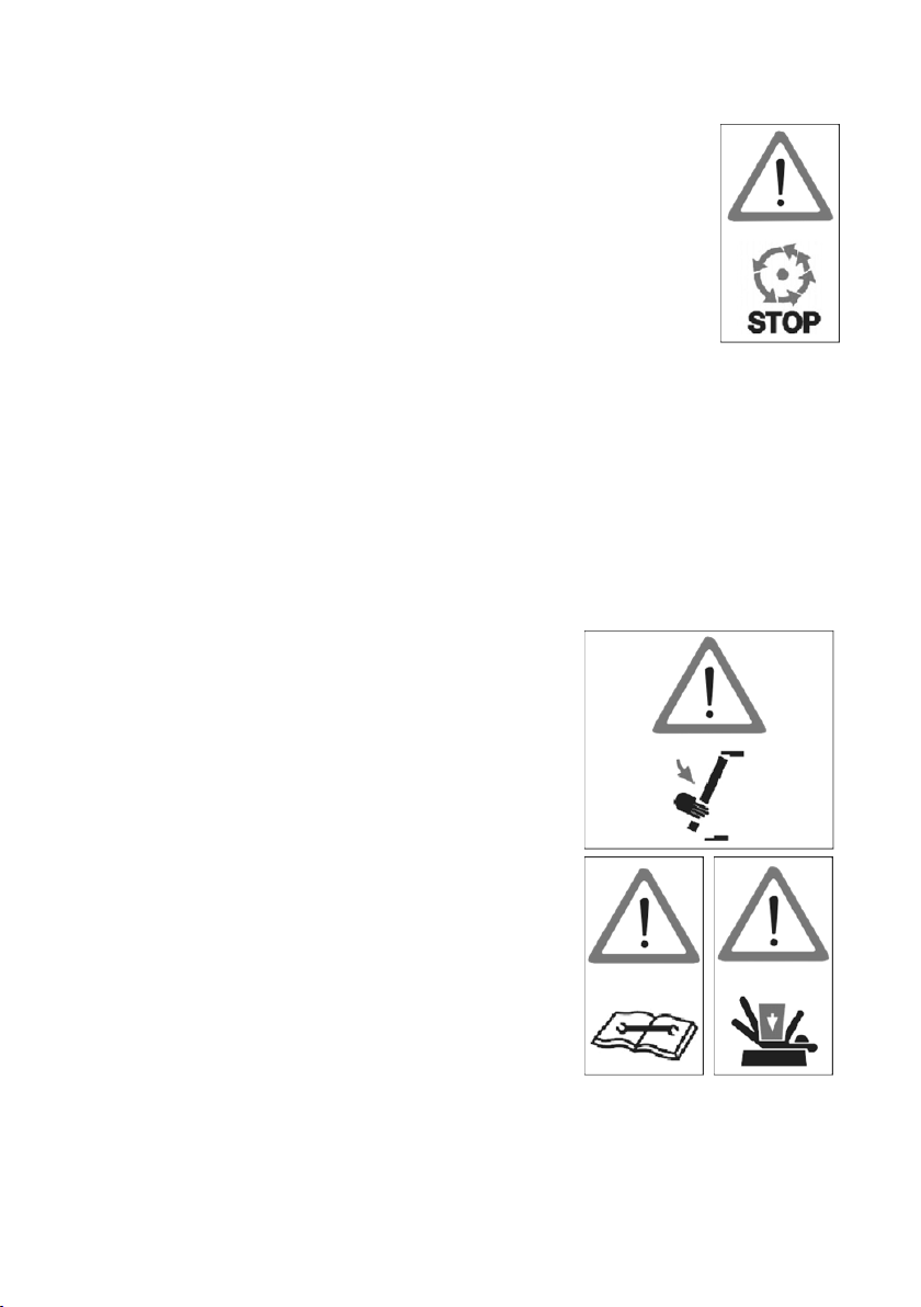
Service and Maintenance
Servicing and maintenance of the fire pump must be
carried out by onl y t he persons who have professional
knowledge, who are familiar with the device, and who
understand laws and regulations regarding safety and
accident prevention.
Before starting maintenance work, turn the main switch
off to stop the engine.
Disconnect the negative terminal of the battery.
Before starting maintenance work, securely place the portable fire pump
on the ground.
Do not touch the exhaust pipe, the muffler and the other engine parts until
these parts will be cold enough. These parts could be very hot and will
cause severe burns.
Safety devices
After protection devices (such as muffler guard)
have been disassembled as part of servicing
and maintenance work, install them back as
soon as possible to their original positions, and
make sure that they are in safe secure
condition.
Check the portable fire pump visually and
functionally on a regular basis.
If you find any faulty devices or equipment,
remove it immediately, and repair or replace it,
if necessary.
Failure to do so may cause an accident. After it
has been repaired or replaced, make sure that
it functions correctly.
Electrical equipment
Only expert electricians or trained staff
members should handle electrical equipment.
When removing the battery cable from the
electrical equipment, always disconnect the
negative (-) cable first.
When installing the battery cable, be sure to
connect the positive (+) cable first before
connecting the negative (-)
Do not place any metal on the top of or around
the battery.
Doing so many causes a short circuit
Use a fuse with the same specifications as the
original one when replacing it. Using a fuse that
has a greater capacity than the rated value may
damage the equipment.
While the engine is running, do not touch the
high voltage ignition wire attached to spark plug.
This wire carries very high voltage which will
cause injury and bodily harm.
Check the electrical equipment of the fire pump
on a regular basis.
.
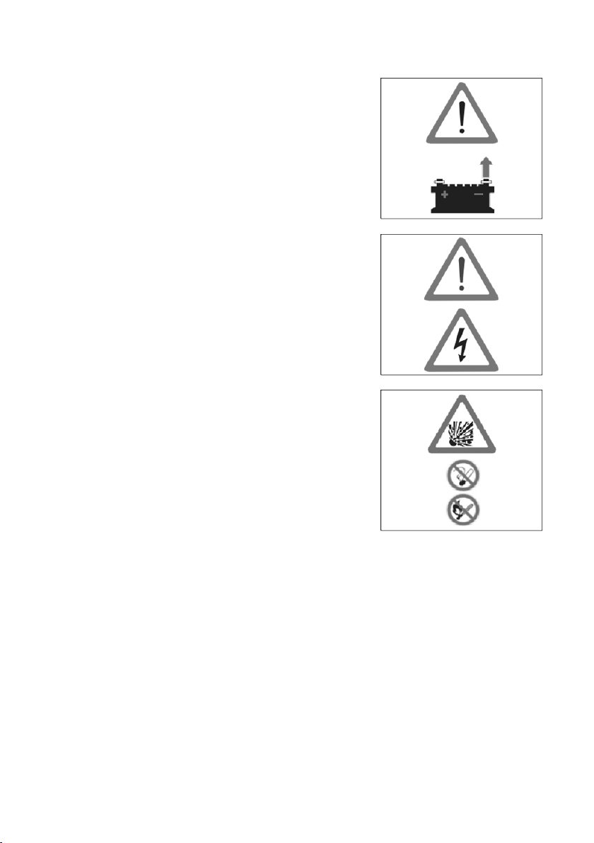
Battery
Follow any safety-related instructions shown on
the battery.
The battery can generate flammable hydrogen
gas that may cause an explosion.
Do not charge the battery in closed location.
Do not smoke around the battery.
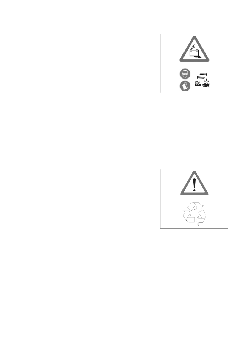
The battery electrolyte is caustic and may
cause personal Injuries.
・ Always wear protective clothing.
・ Always wear protective gloves.
・ Always wear protective glasses.
・ Do not tilt the battery.
Doing so may cause the battery electrolyte to
leak out from the vent hole.
Disposal
Dispose the disused batteries according to
relevant laws and regulations.
Genuine parts
When replacing parts for servicing and
maintenance of the portable fire pump, only use
Tohatsu genuine parts.
If genuine Tohatsu parts and accessories are not
used, it may adversely affect the functioning and
safety of the fire pump. Use genuine Tohatsu
parts only.
Tohatsu bears no responsibility for any personal
injuries or equipment damage that may result
from use of parts or accessories obtained from
outside sources.
Environmental protection measures
Dispose of oil, fuel, batteries, etc. according to
relevant environmental laws.
Do not dump waste into the ground, water, or
sewerage.
Store fuel only in the specified container.
When disposing of parts, follow the correct
disposal procedure.
Water-prohibiting substance
Do not discharge water to water-prohibited
substance.
Use of water
Do not pump combustible liquids, chemical or
caustic liquids.
Customer Service
If any problems occur during servicing and
maintenance work of the portable fire pump,
contact our Customer Service.
Address : 3-5-4 Azusawa, Itabashiku,
Tokyo, JAPAN
FAX : +81-3-3966-2951
Phone : Service +81-3-3966-3380
Email : tohatsu-pservice@tohatsu.co.jp
Overseas section fire protection sales department
+81-3-3966-3137
bousaiex@tohatsu.co.jp

CONTENTS
1 SPECIFICATION ................................................................................................. 1
1
2 OPERATING DEVICE .................................................................................... 4
2
3
3 LABELS ........................................................................................................... 7
4
4 OPERATING PRECAUTION ........................................................................ 8
5 DESCRIPTION OF DEVICE ....................................................................... 10
5
6 PREPARATION FOR OPERATION.............................................................. 22
6
7 USE OF CONTROL PANEL ........................................................................... 26
7
8 STARTING THE ENGINE ................................................................................ 34
8
9 PRIME AND DISCHARGE .......................................................................... 38
9
10 STOPPING THE ENGINE ........................................................................... 49
10
11 MAINTENANCE AFTER OPERATION ........................................................ 50
11
12 MAINTENANCE IN COLD CONDITION ................................................... 56
12
13
13 USE OF ACCESSORY ................................................................................ 59
14
14 PERIODICAL INSPECTION ....................................................................... 61
15 SERVICE AND MAINTENANCE ............................................................... 63
15
16
16 TROUBLESHOOTING................................................................................. 74
17
17 APPENDIX ..................................................................................................... 80
18
18 TOOLS AND STANDARD ACCESSORY ................................................. 81
19 WIRING DIAGRAM ...................................................................................... 82
19

1
SPECIFICATION
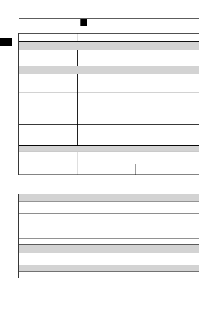
Model VF53AS VF63AS-R
1
9
10
13
14
15
16
Description Portable fire pump
Engine
Manufacturer TOHATSU CORPORATION
Model 3WF61A
Type 4-stroke, EFI
Bore × Stroke 61 mm × 60 mm
Number of Cylinder 3
Piston displacement 526 ml
Authorized output 22 kW (30 PS)
Fuel type Unleaded petrol RON91
Fuel tank capacity 10 L (2.6 gal(US))
Fuel consumption
Engine oil API SF to SM SAE 10W 30/40
Engine oil tank capacity
Engine lubrication Trochoid pump
Cooling system Water cooling
Ignition Flywheel magneto, C.D. Ignition
Spark plug NGK DCPR6E
Starting system Electric starter and Manual starter
Lubrication Wet sump
Fuel system Electronic fuel injection
Battery 12 V-16 Ah/5 h
Floodlight bulb *1 12 V-55 W
*1 Option (Floodlight)
9.5 L/h (2.5 gal(US)/h)
1.9 L/0.50 gal(US)
(When replacing oil filter:2.0 L/0.53 gal(US))
1
22
33
44
55
66
77
88
9
10
1111
1212
13
14
15
16
17
18
19
17
18
19
1
1
Primer
1
SPECIFICATION
Model VF53AS VF63AS-R
1
Type Rotary-vane vacuum pump (Automatic suction)
Max. suction height Approx. 9 m (29.5 ft.)
Pump
Type Single suction, single stage, turbine pump
Number of delivery
outlets*1
Discharge valve type
Discharge port coupling
Suction port coupling
Pump performance
(Suction height: 1 m)
9
Dimensions and weight
Length x Width x Height
10
Mass (DRY)
*1 Twin outlet standard
Materials
13
14
15
16
17
18
19
Engine
Crankcase, Cylinder,
Cylinder head
Crankshaft Steel
Connecting rod Aluminum alloy
Piston Aluminum alloy
Pump shaft Chromium-molybdenum steel with metal plating
Muffler Steel / Stainless
Pump
Pump casing, Pump cover Aluminum alloy
Impeller Aluminum alloy
Shaft seal
Type Mechanical seal
2
Ball valve, Screw down valve
JIS fire thread (B-9912) 2-1/2” (65 mm) male
BSP thread 2-1/2" (65 mm) male
JIS fire thread (B-9912) 3” (75 mm) male
BSP thread 4" (100 mm) male / female
3
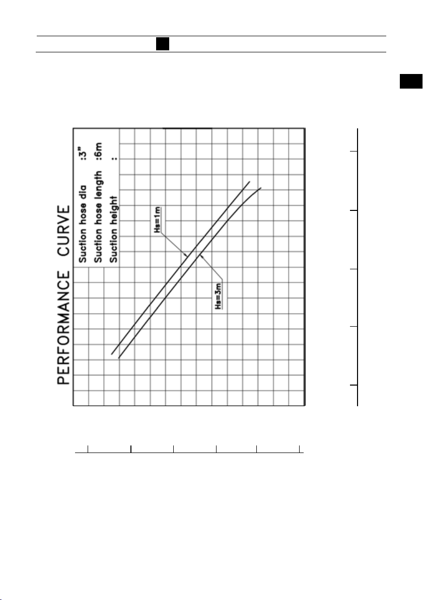
/min at 0.6 MPa(87 psi)
1.2 m
0.95 m3/min at 0.8 MPa(116 psi)
670790740 mm (26.431.129.1 in.)
101kg (223lbs.) 102.5kg (226 lbs.)
Aluminum alloy
22
33
44
55
66
77
88
9
10
1111
1212
13
14
15
16
17
18
19
2
1
SPECIFICATION
Performance Curve
1
9
10
13
14
15
16
17
18
1.1
160
0.9
1.0
140
0.8
120
0.7
0.6
(MPa)
100
80
1
22
33
44
55
1200
66
300
/min)
3
1000
77
88
250
9
800
(L/min) (×1/1000 m
10
200 350
1111
Delivery flow Q (gal(US)/min)
1212
600
13
150
0.5
14
15
60
16
Total delivery pressure P (psi)
17
18
19
19
3
1
VF53AS
2
Warning lamp
Auto priming
switch
9
10
13
14
15
16
17
18
Manual suction
knob
Control panel
Fuel tank
Plug cap
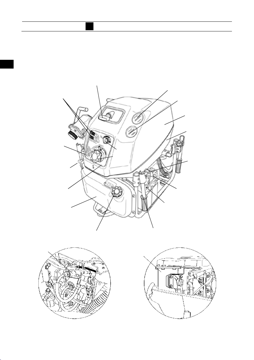
2
OPERATING DEVICE
Manual starter handle
Main switch
Throttle dial
Fuel tank cap
Vacuum pump
Pressure gauge
Oil level gauge
Floodlight projector and
battery charging socket
Carrying handle
Vacuum gauge
Top cowl
Bottom cowl
Engine oil tank
cap
1
22
33
44
55
66
77
88
9
10
1111
1212
13
14
15
16
17
18
19
19
4
1
9
10
13
14
15
16
17
18
19
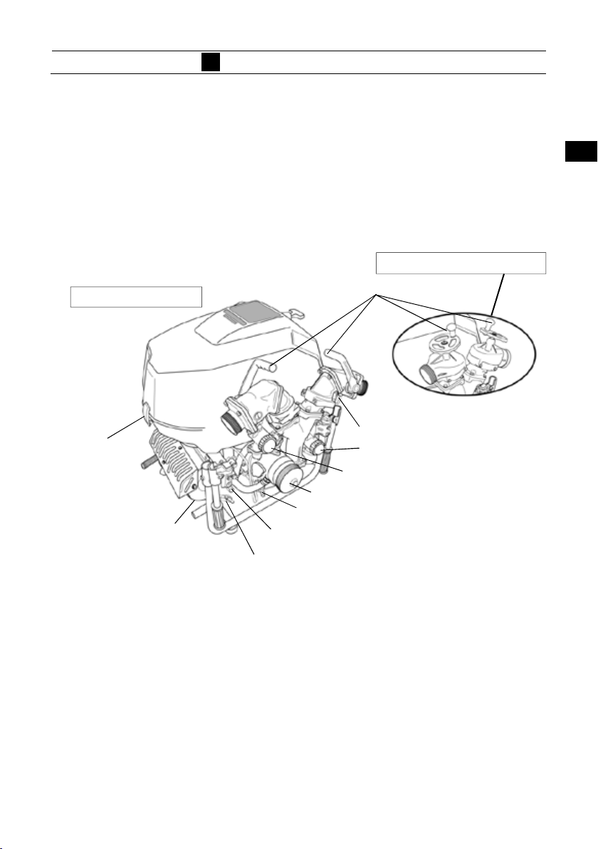
VF53AS
Ball valve type
Latch
(for top cowl)
Muffler
2
OPERATING DEVICE
Discharge valve
Vacuum pump strainer
Suction hose coupling cap
Pump drain valve
Air valve for drainage
Muffler drain valve
Screw down valve type
Discharge valve’s drain
Cooling water strainer
1
22
33
44
55
66
77
88
9
10
1111
1212
13
14
15
16
17
18
19
5
1
9
10
13
14
15
16
17
18
2
OPERATING DEVICE
VF63AS-R
Different operation part from VF53AS
Operation
mode switch
Stop switch
Warning lamp
Main/Start
switch
Priming water
mode switch
1
22
33
44
55
66
77
88
9
Control panel
10
1111
Throttle dial
1212
13
14
15
16
17
18
19
19
6
1
9
10
13
14
15
16
17
18
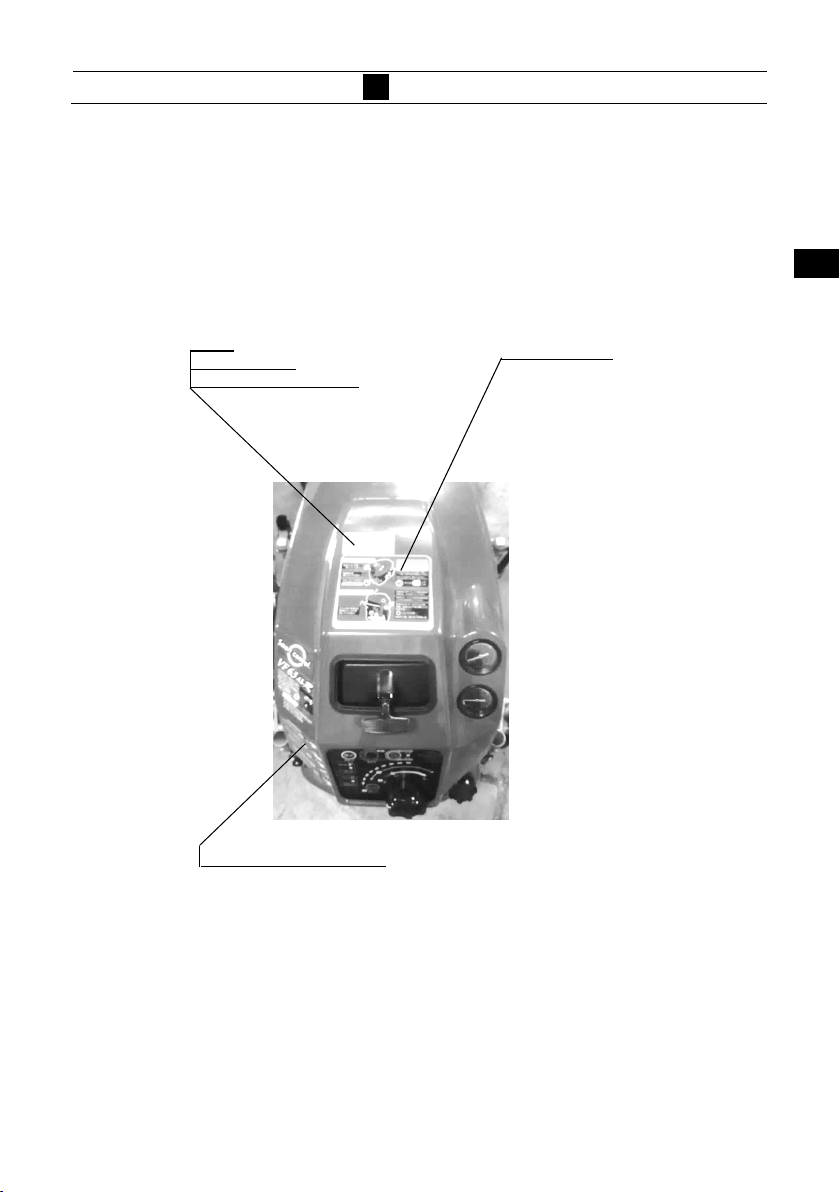
3
Label
Danger : Fuel
Warning : Exhaust gas
Operation procedure label
3
LABEL
1
22
33
44
Instruction label
55
66
77
88
9
10
1111
1212
13
14
15
16
17
18
19
19
7

4
OPERATING PRECAUTION
Installing pump
1
4
NOTE
9
10
13
14
15
16
17
18
・The fire pump must be installed on level ground.
・
Otherwise, an accident may occur.
・
If the fire pump should be installed on uneven ground,
it must be secured.
・Place the pump as near as possible to water source, and
water suction height as low as possible.
・When putting the portable fire pump down on the ground, put
it gently and horizontally.
・In case of the inclined location or uneven ground, make sure
that water suction hose is lower than suction port of the
pump.
・In case of the suction hose is put undulated, air can be left
easily in the hose, and possibly cause suction inability when
the water discharge valve is opened.
・In case of the suction inability due to air remaining in the
suction hose, set the water discharge valve half-opened, and
operate vacuum pump until water is discharged continuously.
(More operation of vacuum pump for 3 to 5 seconds from
beginning of water discharge.)
・Be sure to install strainer and basket at the end of suction
hose. If the pump may suck sand or mud of the water source
bottom, place sheet below the basket.
・Strainer and basket of suction hose should be placed more
than 30 cm below water surface to prevent suck of air.
・Discharge hose should be arranged not to be bent.
19
1
22
33
44
55
66
77
88
9
10
1111
1212
13
14
15
16
17
18
19
8
1
9
CAUTION
4
OPERATING PRECAUTION
・When installing the portable pump in a vehicle, place
the vehicle on a level place, and install the pump.
・
When installing the portable pump in the vehicle,
make sure to apply the brakes of the vehicle in order
to stop the wheels. A serious accident may occur if the
vehicle moves.
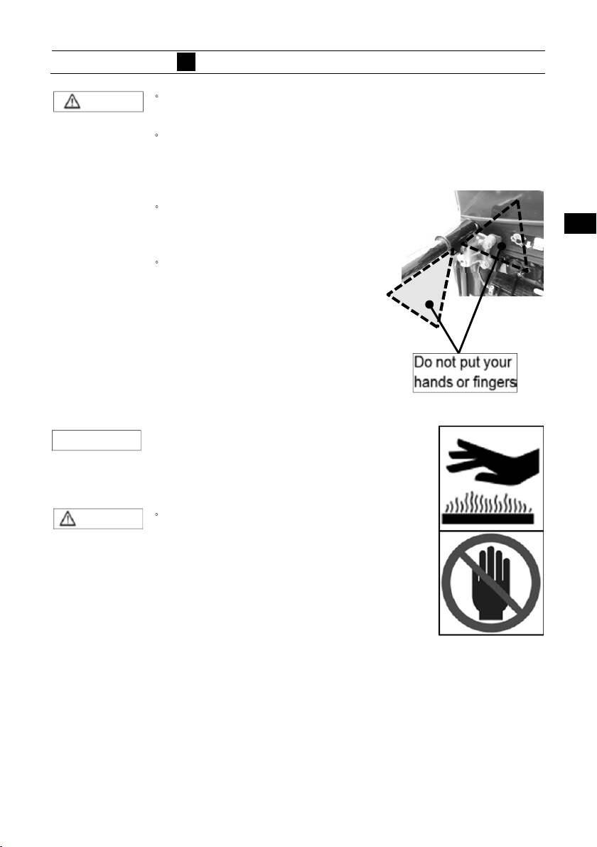
Do not put your hand or finger
・
in the retractable part when
using the handle.
When transporting the portable
・
fire pump, assign one person
per handle. Also, when you
transport the portable fire pump,
it should be transported
holding the handle firmly on
each to avoid falling down the
pump.
1
22
33
44
55
66
77
88
9
10
13
14
15
16
17
18
19
CAUTION
NOTE
・When lowering the portable fire pump
to the ground, lower it gently and
horizontally.
・
Do not touch the exhaust pipe and the
muffler while the engine is running, or
for more than 10 minutes after the
engine has been stopped. These parts
are very hot and will cause severe
burns.
9
10
1111
1212
13
14
15
16
17
18
19
5
DESCRIPTION OF DEVICE
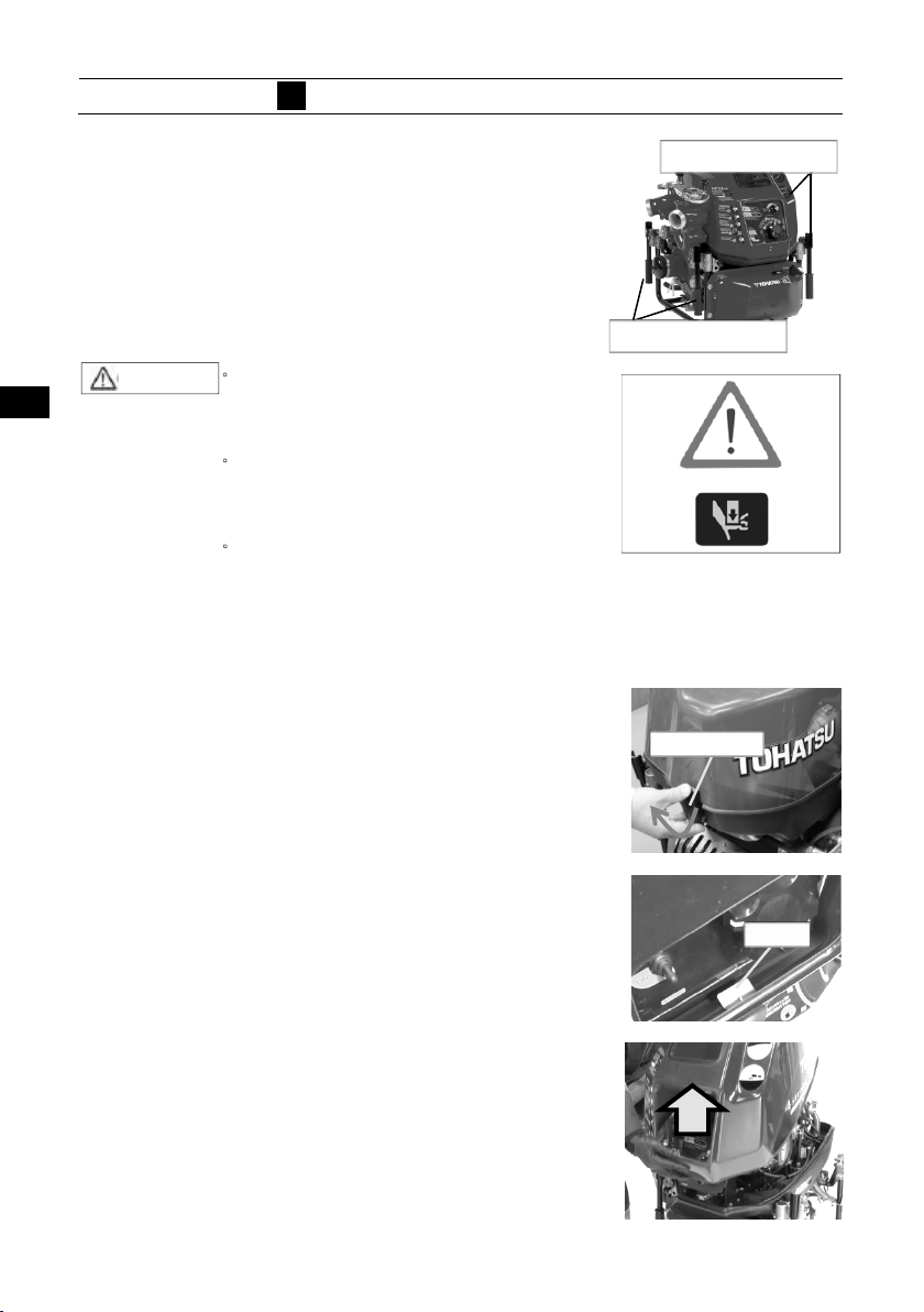
Carrying handle
1
9
The fire pump is equipped with four carrying
handles. The handles can be manually folded, and
opened by turning them by 90 degrees.
Personal injuries may occur
CAUTION
・
when opening or closing the
handle.
Do not put your hands or fingers
・
into the retractable part when
operating the handle.
To prevent injuries, two persons
・
should work together when
carrying and placing the pump.
Opening cowl
10
13
14
15
16
17
18
1. Lift the latch up on the rear side and remove the
cowl.
2. Remove the cowl latch from the plate at the front
side of the pump.
Remove the cowl.
3.
Carrying handle
Carrying handle
Cowl latch
Plate
1
22
33
44
55
66
77
88
9
10
1111
1212
13
14
15
16
17
18
19
19
10

Assembling cowl
1
Assembling order is in reverse order of the opening.
Suction port
The diameter of the thread for the fire pump is
9
10
JIS fire thread (B-9912) 3” (75 mm) or BSP thread 4"
(100 mm).
13
14
CAUTION
15
16
17
18
5
DESCRIPTION OF DEVICE
・ Pay attention to have the starter
handle for manual starting go through
the window at the front- upper side of
the upper cowl.
if you insert your finger into the
・
suction port while the pump is
running, you may be seriously
injured by the spinning inducer.
A strainer must be installed at the
・
suction port.
Do not run the pump if the strainer
・
is not installed. If the pump is
running without the strainer,
gravel may enter the pump and
causes significantly reduced water
discharge capacity.
Starter handle
Thread
Suction port
1
22
33
44
55
66
77
88
9
10
1111
1212
13
14
15
16
17
18
19
19
11
Discharge port
1
The diameter of the thread for fire pump is
5
DESCRIPTION OF DEVICE
1
JIS fire thread (B-9912) 2-1/2” (65 mm),
BSP thread 2-1/2" (65 mm)
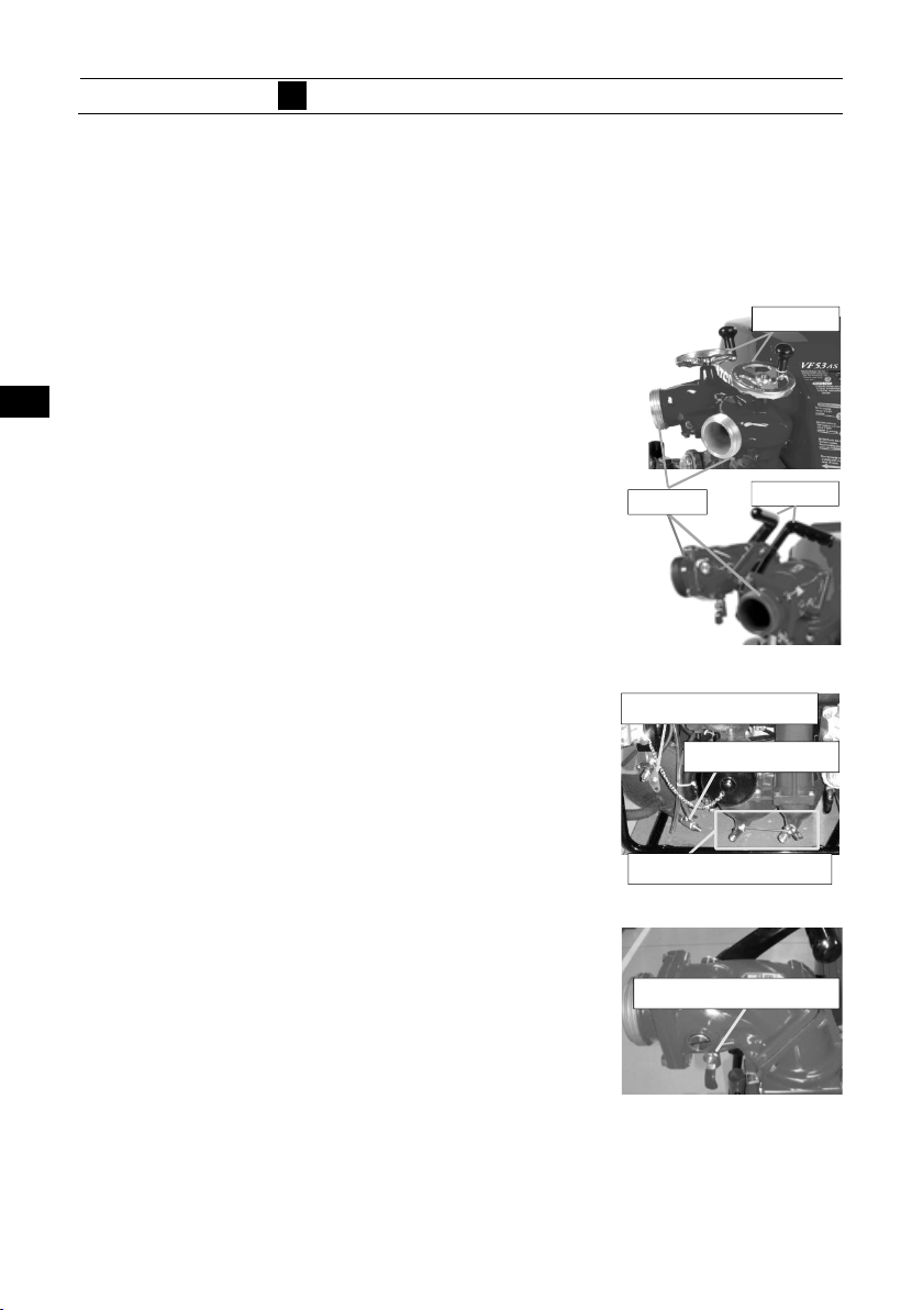
Discharge valve
Use discharge valve handle for opening and
closing
the discharge valves.
Screw down discharge valve _______
Ball cock discharge valve
__________
9
10
Drain valve
Use the drain valves to drain water from the
pump.
Drain valves:
-at the pump case.
13
14
15
16
-at the muffler.
-from the engine. (Air intake valve to assist
drainage.)
-at the ball cock discharge valves. (Only for
ball cock discharge valve type.)
17
Handle
Thread
Valve-air for drain
Valve(Muffler)
Valves(Pump case)
Valve(for ball valve)
Handle
22
33
44
55
66
77
88
9
10
1111
1212
13
14
15
16
17
18
19
18
19
12
Priming knob
1
・Use for priming water by manual operation.
・
After starting the engine, pull the priming knob to
suction water.
After priming water has been completed, return
・
the priming knob to its original position.
Fuel tank
5
DESCRIPTION OF DEVICE
Priming knob
1
22
33
44
55
66
77
9
10
13
14
15
16
17
18
19
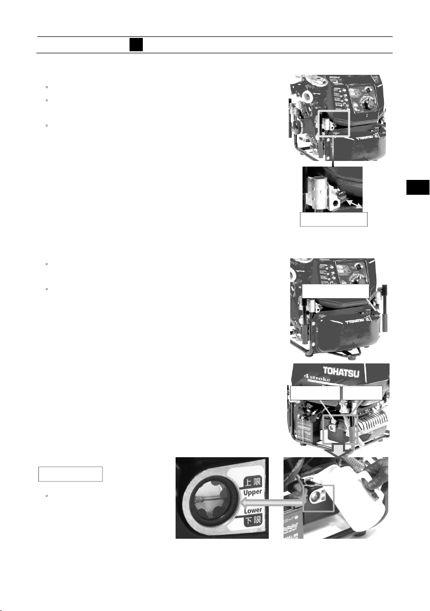
・Refill appropriate amount of gasoline to the fuel
tank.
Close the fuel tank cap all the time except refuel.
・
Engine oil
1.
Check the engine oil level before engine start.
To confirm the engine oil level correctly, keep
2.
the engine stopped for more than 24 hours.
After that, check the oil level.
3. Refill appropriate amount of oil to the oil pan.
4. Close the Oil tank cap all the time except filling.
NOTE
Fill the 4-stroke engine oil.
・
Fuel tank cap
Filler cap Oil pan
88
9
10
1111
1212
13
14
15
16
17
18
19
13
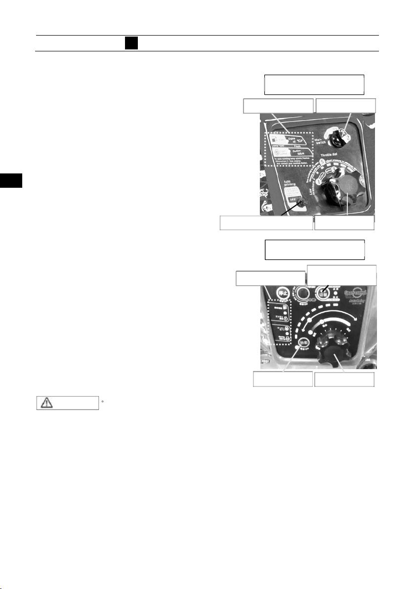
Control panel
1
The control panel is equipped with all
the necessary operating and control
instruments
Main switc h
・
Throttle dial
・
・All warning lamps
・
Auto priming switch.(VF53AS)
Priming water mode switch.(VF63AS-R)
as follows.
5
DESCRIPTION OF DEVICE
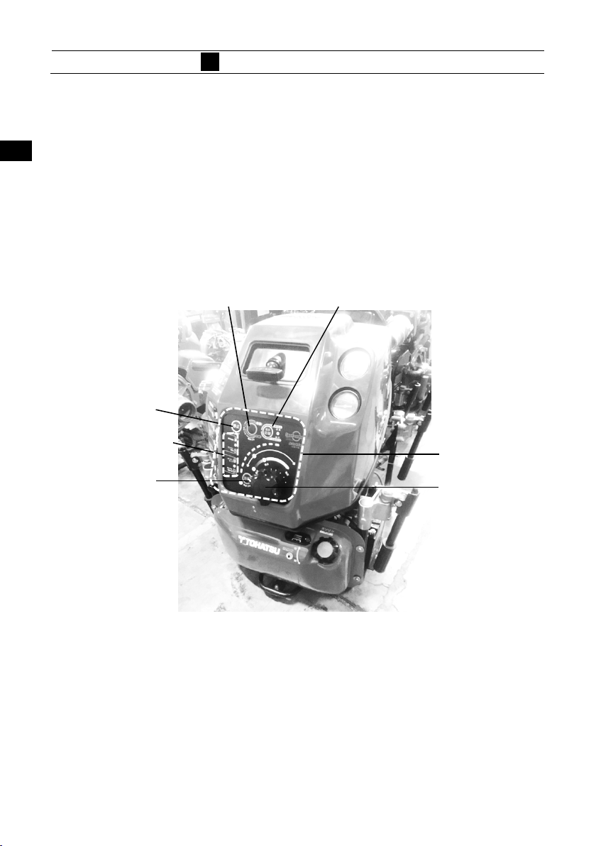
Warning lamp
VF53AS
Main switch
1
22
33
44
55
Warning lamp & buzzer
Turning the main switch to the “ON”
9
10
13
14
position, the lamp and buzzer check
mode starts
The warning lamps turn on and the
warning buzzer sounds for a moment
while the check mode operates.
If the lamp and buzzer check mode
would show failure, refer to “Chapter 16
TROUBLESHOOTING”
cause.
CAUTION
15
16
17
Auto priming switch
Warning lamp
.
to eliminate the
Main switch
Remove the cause of failure by following “Chapter 16
・
TROUBLESHOOTING”.
Throttle dial
VF63AS-R
Priming water
mode switch
Throttle dial
66
77
88
9
10
1111
1212
13
14
15
16
17
18
19
18
19
14
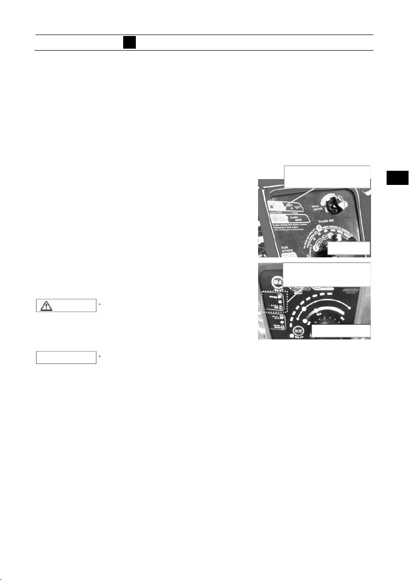
5
DESCRIPTION OF DEVICE
The monitor indicates the following information:
1
9
10
13
14
15
16
17
18
・Fuel level warning
・Engine oil pressure warning
・Overheat warning
・Suction failure warning
Fuel and Engine oil warning
In case of fuel level in the fuel tank is below
approximately 1/3, the warning lamp turns on
and the warning buzzer sounds continuously
when the main switch is turned on.
In case of oil pressure drops , the warning lamp
blinks slowly and the warning buzzer sounds
continuously when the main switch is at ON
position.
In case of oil pressure switch is defective or the
circuit is disconnected, the warning lamp blinks
slowly when the main switch is turned on.
CAUTION
NOTE
・ In the case of slow blinks or
lighting, take countermeasures
following “Chapter 16
TROUBLESHOOTING”
・ The lamp turns on and warning
buzzer sounds instantaneously
when the main switch is turned
on, is normal. The lamp turning
on instantaneously shows the
system check operation, is done.
Fuel and
Engine oil warning
VF53AS
Fuel and
Engine oil warning
VF63AS-R
1
22
33
44
55
66
77
88
9
10
1111
1212
13
14
15
16
17
18
19
19
15
 Loading...