

TOHATSU VC85BS, VC82ASE, VC72AS, VC52AS Quick Start Up Manual
MAIN
SWITCH
3
O
F
F
O
N
S
T
A
R
T
VC85BS•VC82ASE•
VC72AS•VC52AS
Quick Start Guide
1. BEFORE OPERATION
Gasoline Engine Oil
Countermeasuring when the monitor lamp is ON.
8. USE OF OK MONITOR
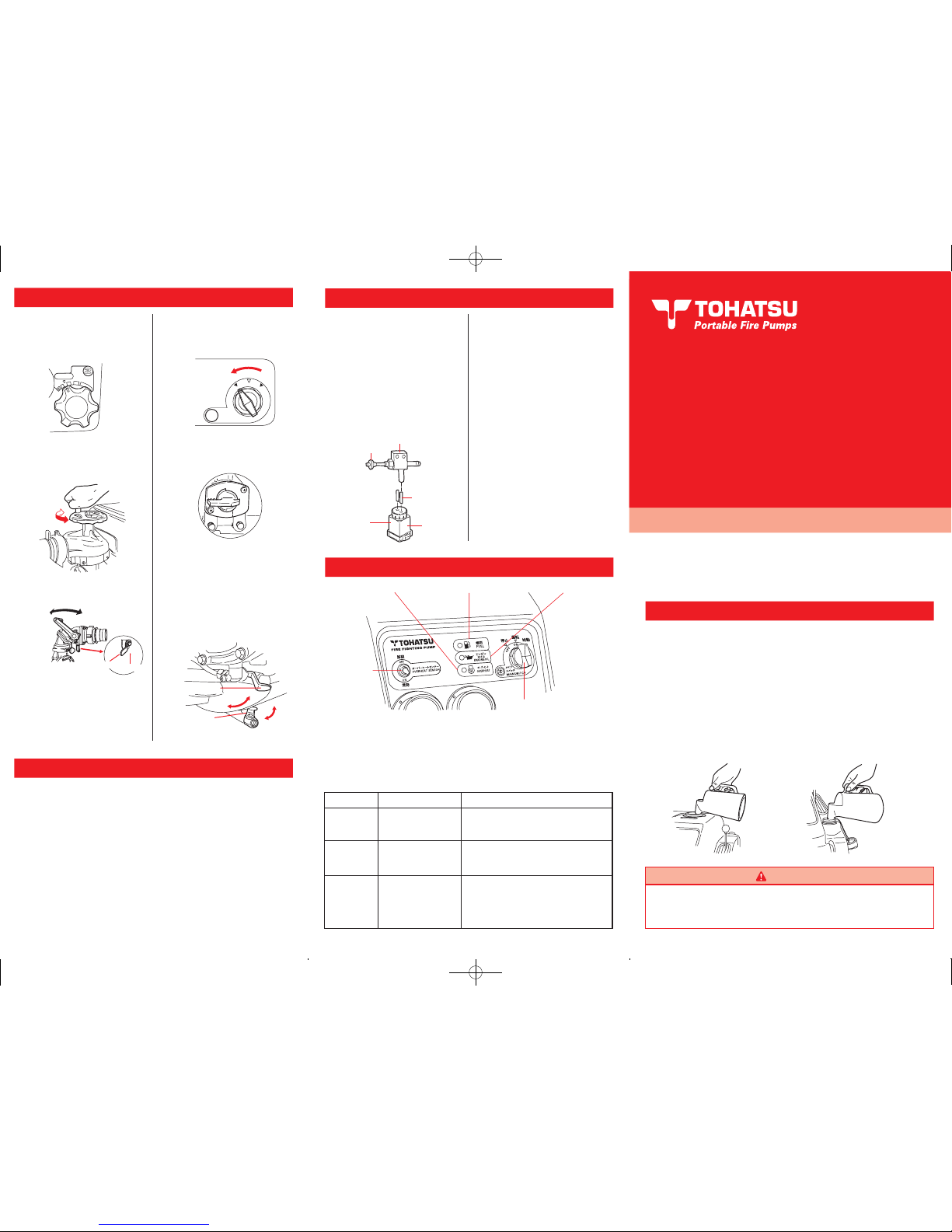
5. STOPPING
1 After stopping the
engine, close the fuel
cock.
2
Pull the knob of the
drain valve. (Fuel in the
float chamber will flow
out.)
3
Turn the main switch
to OFF position.
4
Close the fuel cock.
5
Open the drain cocks.
After checking all the
water has been
drained from the
pump, close the cocks
.
1 Battery initial charge
The battery mounted on the engine can be used immediately after filling
cells with electrolyte enclosed with battery (It is better to charge the
battery using the automatic battery charger after filling electrolyte). Do not
add distilled water because this is a sealed type battery. Please refer to the
INSTRUCTIONS on the battery.
2
Fuel & Engine oil
Fill gasoline (87 octane minimum at pump posted rating…91 based on the
research octane rating method) into the fuel tank. Fill two stroke engine oil
into the oil tank.
Maintenance after pumping seawater or foul water
After pumping seawater or foul water, flush fresh clean water
through the pump with the pump running to thoroughly clean
the inside.
And operate the vacuum pump for 5 seconds at low engine
speed in order to clean the vacuum pump
.
3
After all the fuel has
drained, release the
knob. (The drain valve
will return to the
closed position.)
4
Fuel from the drain pot
should be returned to
the fuel tank
.
Dispose of fuel if contaminated
with water, dirt or other
substances
.
7. Draining Fuel from the Carburetor
WARNING
Dry running of engine for over two minutes will cause seizure
of engine parts. Start suction of water immediately after
starting engine.
It is necessary to take a countermeasure if the lamp is on when turning the main
switch to the position of
“Operation”.
Monitor lamp
Fuel
Engine oil
Overheat
Level of fuel has
dropped below one
third of tank capacity
.
Supply fuel.
Supply 2 stroke engine oil.
Check the cause and remedy it. Turn the
overheat sensor switch to
“OFF” position
and start the engine. After co
nfirming the
lamp is off, return the switch to
“ON”
position.
(VC82ASE/72AS/52AS)
Oil level is below
quarter of oil tank
capacity.
Engine stops caused
by lack of cooling
water.
Lamp ON
Action required
1
Return the throttle
dial to low speed
position
.
2
Close the discharge
valve.
Open↔Close
CLOSE
OPEN
Standard Type
Discharge Valve
CLOSE OPEN
OPEN
Ball Cock Type
Discharge Valve (Option)
CLOSE
Be sure to read the instruction manual before operating
Tohatsu fire pump. Being familiar with all aspects of its
application will guarantee best performance.
The pot must
be emptied
each time.
Knob
Drain valv
e
Check the hose
is secured to the
drain pot.
Drain pot
6. PRECAUTIONS AFTER OPERATION
スロットル
THROTTLE
低圧
LOW
低圧
HIGH
始動
START給水SUCTION
ON
FUEL
O
O
C
C
For pump casing
For muffle
r
Printed in Japan No.004-22015-0
Overheat
Overheat
switch
Fuel
Engine oi
l
Main switc
h
QuickGuide_121022.indd 1 12.10.22 10:47:47 AM
WARNING
VC85BS / VC82ASE / VC72AS / VC52AS
1. BEFORE OPERATION
Gasoline Engine Oil
Countermeasuring when the monitor lamp is ON.
8. USE OF OK MONITOR
Fire Fighting Pumps
3
Governor case oil
4 Drain cock
1 Notes on installation
Before using fire pump check governor case oil
level. To check, remove oil gauge, oil level
should be between upper and lower line on the
gauge if necessary, add two stroke engine oil
into the oil gauge insert port.
Make sure the drain cock is closed.
5
Discharge valve
Make sure the discharge valve
is closed.
(1) Set the pump in a place that is flat near water source with
pump easily accessable to ease operation.
(2) Set suction hose rising slope toward pump to prevent
trapping of air.
(3) Connect suction hose and delivery hose to the pump
securely. Put end of suction hose in water source. The
suction hose must have a strainer and a basket.
4. WATER SUCTION AND DISCHARGE
3 Once water is visible in strainer cup
of vacuum pump, it is sign of suction
completed. Return the handle to
original position.
4 Open the discharge
valve.
2
Check water exiting from the vacuum
pump drain pipe. The pressure
gauge moves to the positive range.
5
Open the drain cocks.
After checking all the
water has been
drained from the
pump, close the cocks
.
1
After starting the engine,
lower the vacuum pump
handle to SUCTION side
.
5 Adjust the water
volume and pressure
controlling the
throttle dial
.
1
Open the fuel cock lever
by turning it
downward.
2 Set the throttle dial at
START
▼
SUCTION
position
.
3
Turn the main switch to
START position.
1 Battery initial charge
The battery mounted on the engine can be used immediately after filling
cells with electrolyte enclosed with battery (It is better to charge the
battery using the automatic battery charger after filling electrolyte). Do not
add distilled water because this is a sealed type battery. Please refer to the
INSTRUCTIONS on the battery.
2
Fuel & Engine oil
Fill gasoline (87 octane minimum at pump posted rating…91 based on the
research octane rating method) into the fuel tank. Fill two stroke engine oil
into the oil tank.
Maintenance after pumping seawater or foul water
After pumping seawater or foul water, flush fresh clean water
through the pump with the pump running to thoroughly clean
the inside.
And operate the vacuum pump for 5 seconds at low engine
speed in order to clean the vacuum pump
.
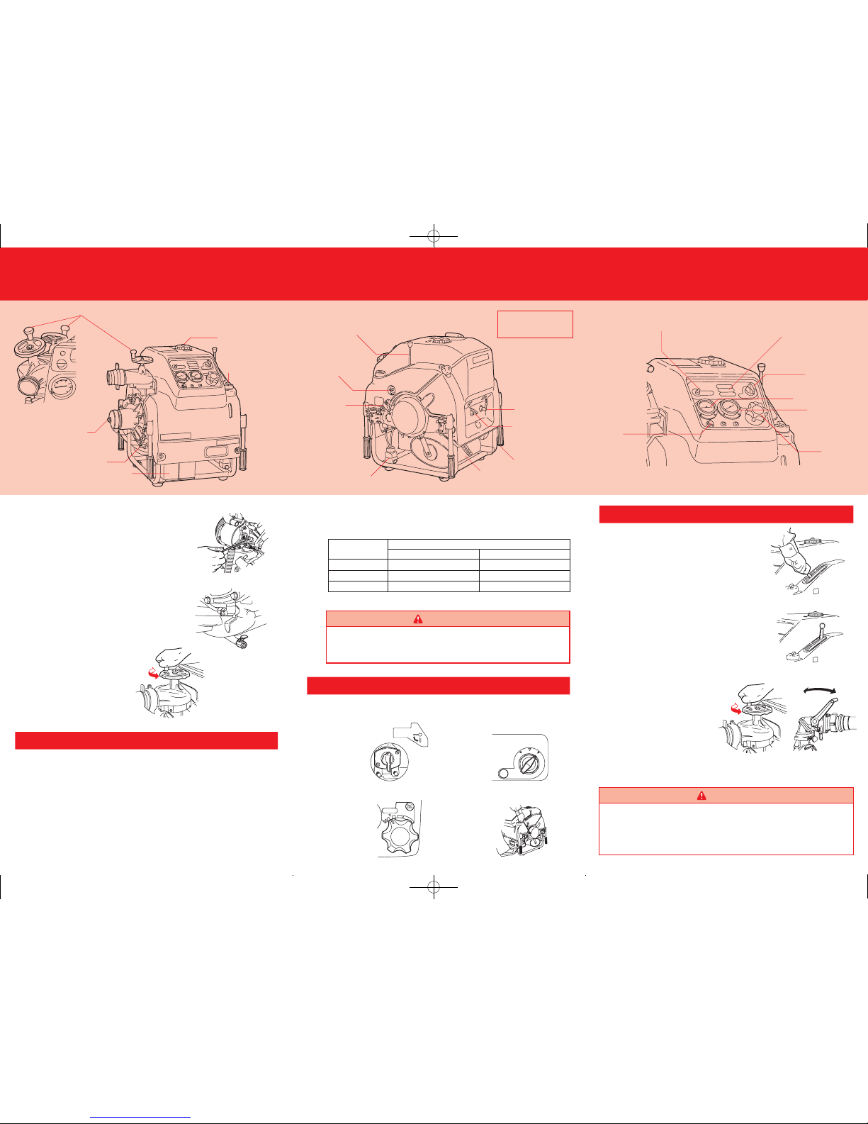
2. LOCATING PUMP
3. ENGINE START
WARNING
Dry running of engine for over two minutes will cause seizure
of engine parts. Start suction of water immediately after
starting engine.
Operation of vacuum pump should be completed within 30
seconds, or the pump may be damaged seriously. If no
vacuum is attained within 30 seconds, troubleshoot the
cause
.
WARNING
When delivery nozzle is not used, pumping plate must be
installed on delivery outlet to avoid engine overheating
caused by lack of cooling water.
It is necessary to take a countermeasure if the lamp is on when turning the main
switch to the position of “Operation”.
Monitor lamp
Fuel
Engine oi
l
Overheat
Level of fuel has
dropped below one
third of tank capacity
.
Supply fuel.
Supply 2 stroke engine oil.
Check the cause and remedy it. Turn the
overheat sensor switch to
“OFF” position
and start the engine. After co
nfirming the
lamp is off, return the switch to
“ON”
position.
(VC82ASE/72AS/52AS)
Oil level is below
quarter of oil tank
capacity.
Engine stops caused
by lack of cooling
water.
Lamp ON
Action required
CLOSE
OPEN
Standard Type
Discharge Valve
CLOSE OPEN
OPEN
Ball Cock Type
Discharge Valve (Option)
CLOSE
Discharge valve handle
(VC82ASE)
Fuel tank cap
Engine oil tank cap
Suction blank cap
Pump casing drain cock
Battery
If electric starter will
not work, use the recoil
starter.
Model
VC82ASE
VC72AS
VC52AS
Nozzle Dia. (mm)
19
21
22
Smallest dia.Largest dia. *
25
36
36
*The largest nozzle dia. in column is the maximum dia. at the 3m of the suction head.
MAIN
SWITCH
3
O
F
F
O
N
S
T
A
R
T
Be sure to read the instruction manual before operating
Tohatsu fire pump. Being familiar with all aspects of its
application will guarantee best performance.
The pot must
be emptied
each time.
drain pot.
Drain pot
(4) Water discharge is made by a branch pipe with nozzle
fitted. Recommended nozzle diameters are within the
range below.
6. PRECAUTIONS AFTER OPERATION
CLOSE
OPEN
スロットル
THROTTLE
低圧
LOW
低圧
HIGH
始動
START給水SUCTION
CLOSE
OPEN
Standard Type
Discharge Valv
e
ON
FUEL
燃料コック
F
U
E
L
O
F
F
FUELC OCK
CLOSED
OPEN
閉
開
O
O
C
C
For pump casing
For muffle
r
OPEN
CLOSE
Printed in Japan No.004-22015-0
Overheat
Overheat
switch
Fuel
Engine oi
l
Main switc
h
The part of rear cowl
formation is different than
one of
VC82ASE.
Vacuum pump handle
Fuel cock
Recoil starter
handle
Fuel drain po
t
Muffle
r
Carrying handle
s
Spark plug (#1)
Spark plug (#2)
Overheat switc
h
(VC82ASE/72AS/52AS
)
Floodlight projecto
r
and battery
charging socket
Monitor lamp
s
Main switch
Compoun
d
vacuum gauge
Compound
pressure gauge
Throttle dial
CLOSE
OPEN
Ball Cock Type
Discharge Valve (Option
)
QuickGuide_121022.indd 2 12.10.22 10:47:50 AM
 Loading...