

Tohatsu VC52AS, VC72AS Owner's Manual

OW N E R’S
M A N U A L
VC52AS
VC72AS
PORTABLE
FIRE PUMP
No .0 03-120 5 4-3

Copyright © 2020 Tohatsu Corporation. All rights reserved. No part of this manual
may be reproduced or transmitted in any from or by any means without the express
written permission of Tohatsu Corporation.

APPLICATIONS
OF THIS FIRE PUMP
USAGE
TOHATSU fire pumps “VC52AS, VC72AS” are manufactured for use in firefighting
operations.
These portable fire pumps are intended only for firefighting activities in collaboration
with general public fire extinguishing equipment.
Using it for other applications is regarded as being used for improper purposes.
The manufacturer of these fire pumps bears no responsibility for any damages that may
result from modification of the fire pump without prior permission from the
manufacture, improper use of the fire pump, or use of the fire pump for applications
other than those stated above.
Note that the use of these fire pumps for applications other than those stated above
can result in personal injury or damage to the equipment.
Using the fire pump within the range of intended uses implies that the user should
follow the instructions provided by the manufacturer relevant to operation, servicing
and maintenance.

Intended people
All persons who operate, service or maintain the fire pump must read and understand
the following items:
・Owner’s manual
・Safety-related instructions on the pump and the other parts such as the battery.
・The other owner’s manuals, such as battery charger.
The portable f i r e pump should be operated by only persons who received training
as operators of fire engines along with each country’s (region’s) regulations.
The range of personal responsibility and supervision must be strictly defined by the
user.
If a person does not have adequate professional knowledge required for his/her
assignment, he/she must undergo relevant training or receive appropriate instructions
from an individual who is actually knowledgeable in operation of the fire pump.
A person who does not have enough knowledge is not permitted to operate the fire
pump.
When using the fire pump, conditions under which an explosion may occur are not
considered.
CAUTION
Keep this manual in a safe place for future reference.
Operators of this fire pump must always refer to all the relevant
manuals in order to avoid errors, personal injuries, and
equipment damage when operating the portable fire pump,
and to maintain faultless operation.
Arrange owner’s manual so that operators can refer to them
where they operate the fire pump.

INTRODUCTION
Thank you for purchasing the TOHATSU Fire Pump.
NOTE
This fire pump has passed a range of quality assurance standards.
Owner’s manual
The portable fire pump complies with relevant laws and regulations.
The manual includes a description for operation and maintenance. Before using this
fire pump, be sure to read and understand the manual thoroughly.
Engine operation
This manual also includes a description for operation and maintenance of the engine.
・The manual is an important item that goes with your portable fire
pump.
・This manual should accompany this fire pump if sold to another
person.
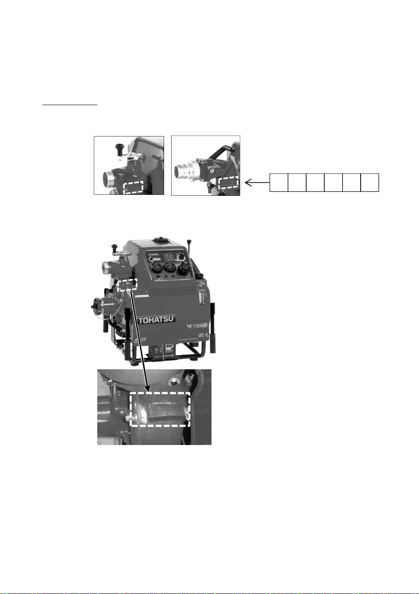
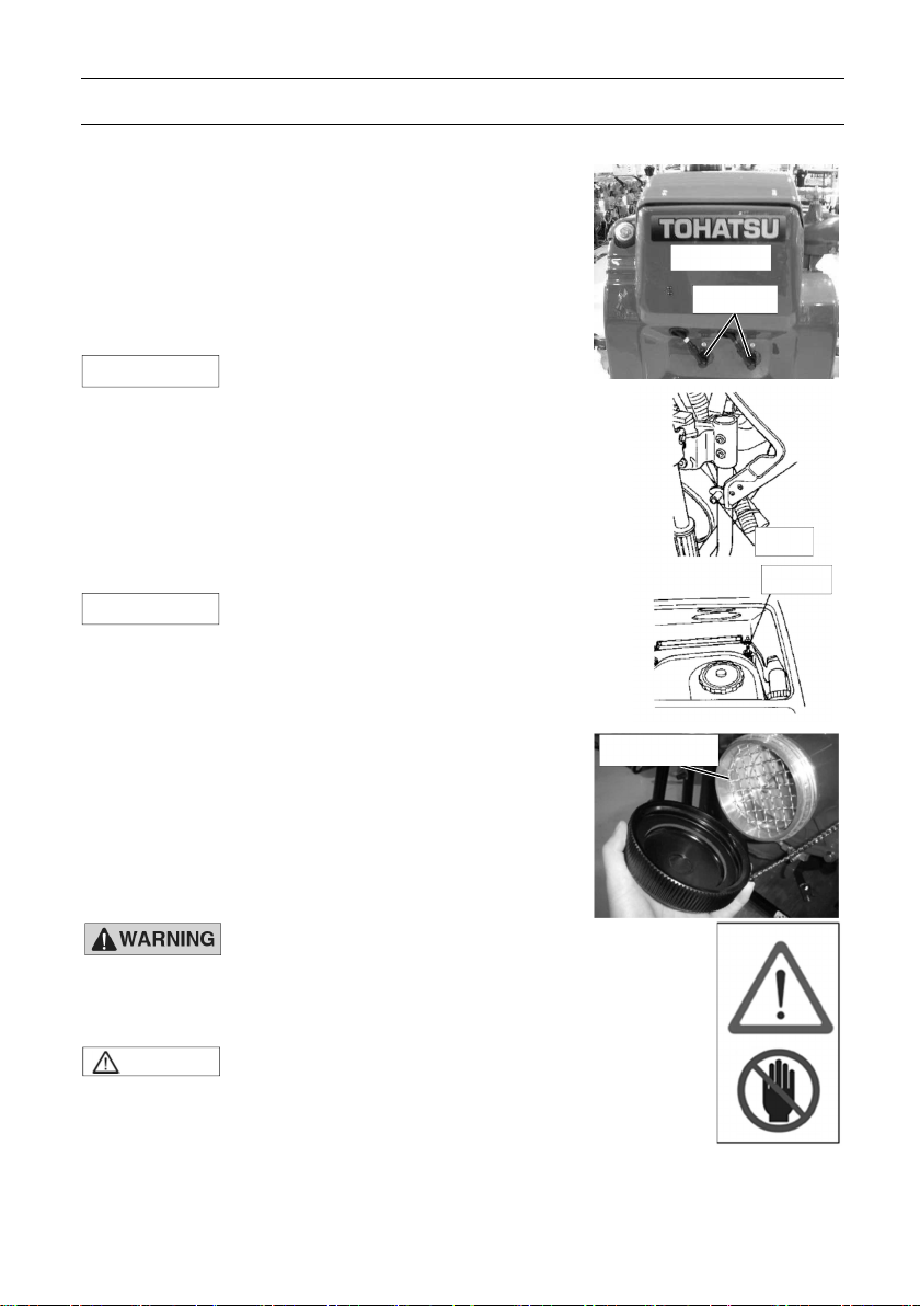
Before using this fire pump, write down the serial number in the following boxes. It will
be useful in the case of asking about servicing, repairs and genuine parts.
Serial Number
The pump serial number (identification number) is marked on the pump casing.
VC52AS
VC72AS
GENERAL SAFETY INFORMATION
CAUTION
Overview
Before operating the TOHATSU fire pump thoroughly
read this manual to understand the proper
operating procedures including “DANGER”,
“WARNING”, “CAUTION” and “NOTE”.
These notices are designed to bring attention to
very important information necessary to ensure
safe, trouble free operation.
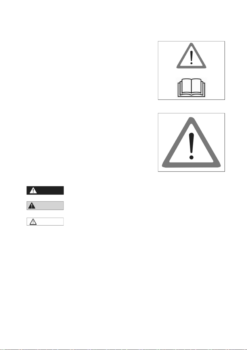
Warning sign
Meaning
This sign is used for safety-related instructions in
this manual.
Be sure to follow all safety-related instructions,
otherwise, personal injury may occur.
Signal words
DANGER
・Failure to observe will result in severe personal injury or
death.
WARNING
・ Failure to observe could result in severe personal injury or
death.
・ Failure to observe could result in personal injury or property
damage.
・This instruction provides special information to facilitate the use or maintenance of
the pump or to clarify important points.
・For attaching position of the warning label, refer to the “CONTENT 3. LABELS”.
・Warning labels should be read clearly at any time.
If the display of the warning label becomes difficult to b e read, it was almost
come off, you must replace paste immediately.
Safety-related instructions and warning signs
Read and follow the safety-related instructions described in this manual and all
warning signs on the portable fire pump thoroughly.
Always keep the warning signs in a legible condition. If any warning sign becomes
illegible or detached, replace it immediately.
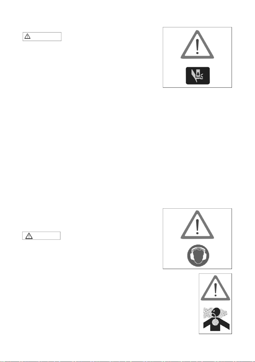
Transporting the portable fire pump
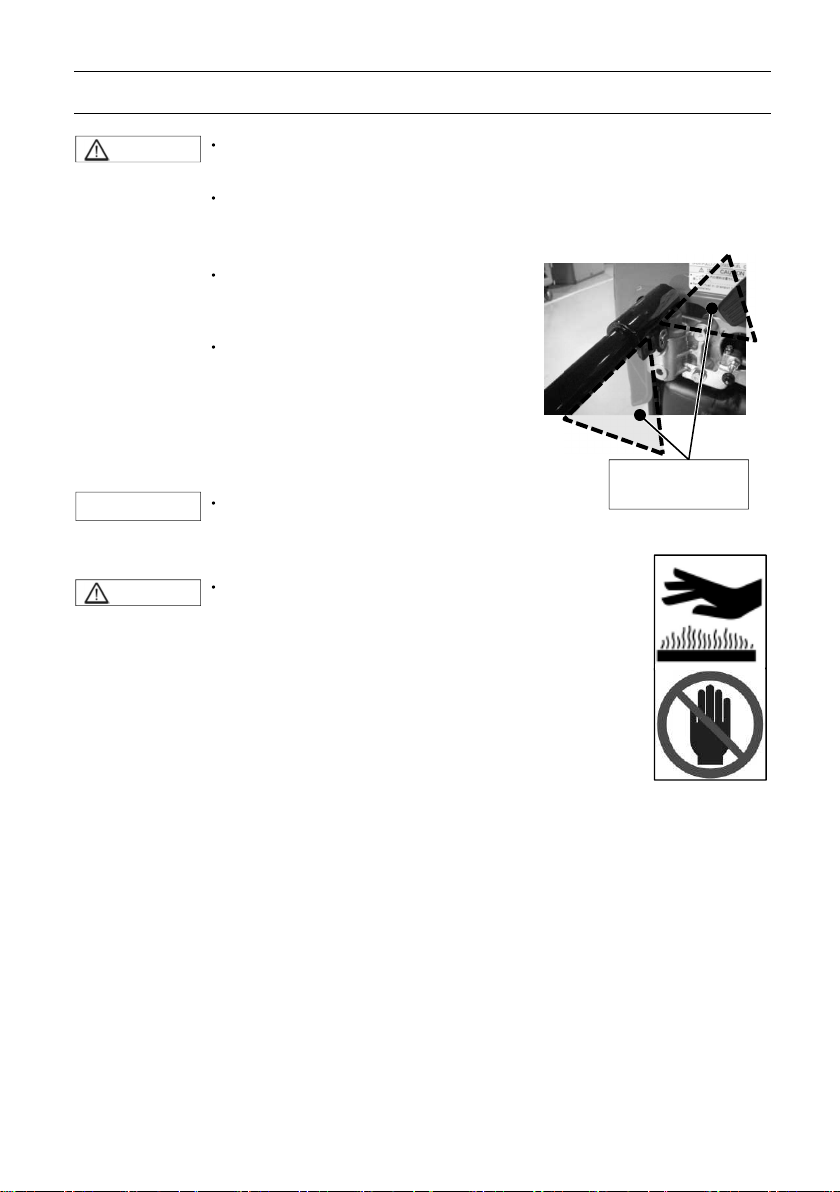
CAUTION
CAUTION
・ Retra cta ble ha ndl e is f olding
type.
・ Do not put hand or finger
between top of retractable handle
and bracket.
・ When transporting the portable
fire pump, assign one person per
handle.
・ Also, when you transport the
portable fire pump, it should be
transported holding the handle
firmly.
・ There is a risk of injury to the leg by
fall.
Durability of protection
When you purchase a new pump, it is placed in
packing box and protected.
Storage of pump after transportation
Keep the pump away from high humidity, and place
it on a horizontal plane.
Disposal of packing box
Dispose the packing box by following the
environmental laws.
Noise
・Wear proper hearing protection
during operation.
Exhaust gas
Fatal hazard from carbon monoxide (CO) poisoning
Exhaust gas emitted from the engine contains carbon monoxide (CO)
etc. that may seriously affect human health.
Do not operate the engine in a room, car, warehouse, tunnel or other
closed locations that have poor ventilation.
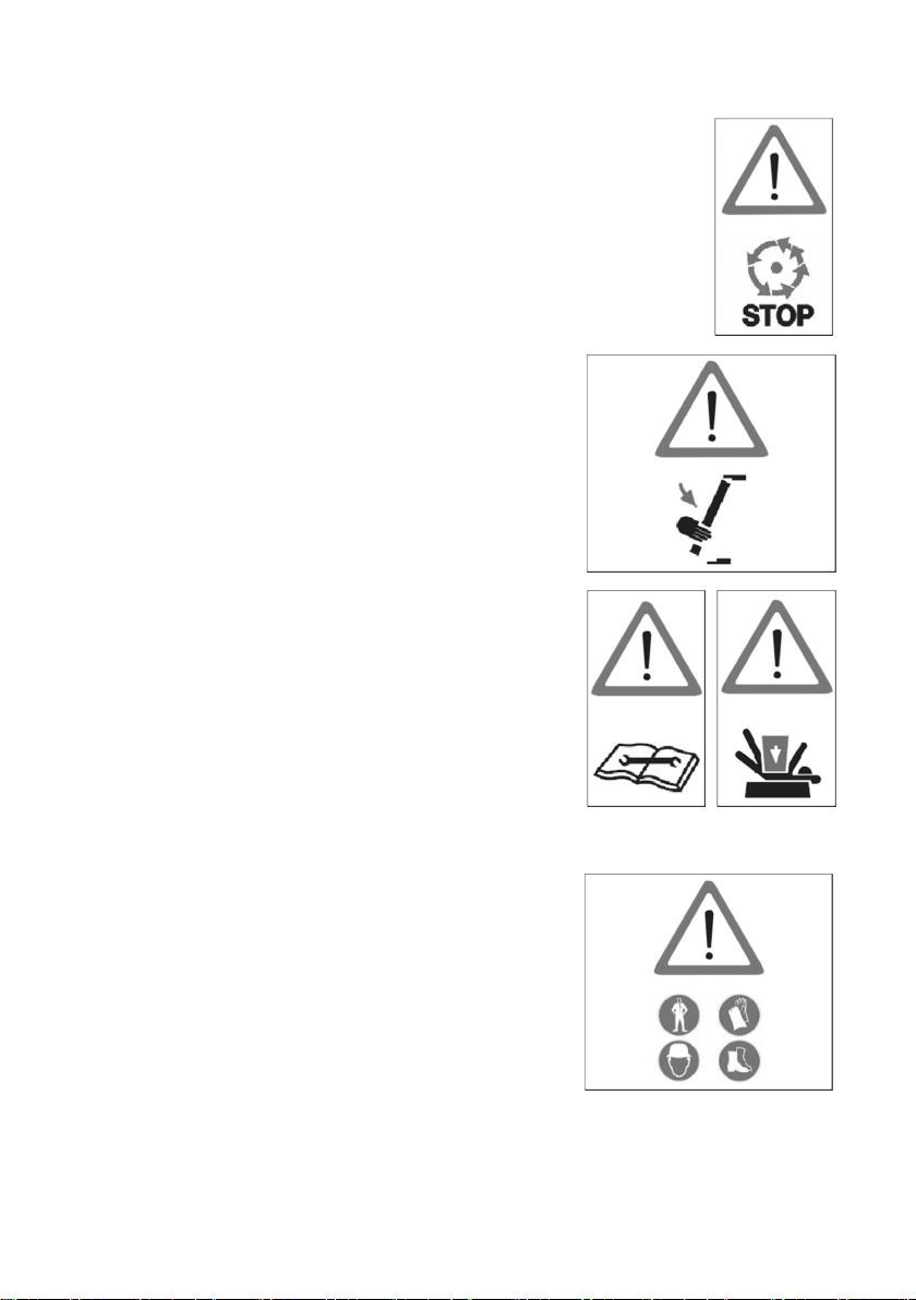
Safety devices
Before operating the portable fire pump, be sure to check that all
the safety devices have been installed in the appropriate positions.
Before removing the safety devices, turn the main switch off.
After protective devices (such as the muffler guard)
have been disassembled as part of servicing and
maintenance work, immediately install them back to
their original locations, making sure that they are in
safe and secure condition.
Check the portable fire pump visually and
functionally on a regular basis.
If you find any faulty device or equipment, remove
it immediately, and repair or replace it, if necessary.
Failure to do so may cause an accident.
After it has been repaired or replaced, make sure
that it functions correctly.
Protective clothing, Protective equipment
During fire extinguishing training or regular
firefighting services, wear normal protective
clothing and equipment to protect your body.
・Fireproof protective clothing
・Fireproof helmet
・Fireproof protective gloves
・Fireproof protective boots
Service, Maintenance
Servicing and maintenance of this fire pump must be carried out by
o n ly t h e persons who have professional knowledge, who are
familiar with the device, and who understand laws and regulations
regarding safety and accident prevention.
Before starting maintenance work, turn the main switch off to stop
the engine.
Disconnect the negative terminal of the battery.
Before starting maintenance work, securely place the portable fire
pump on the ground.
In the case of just after stopping the engine, do not touch the exhaust
pipe, the muffler and the other engine parts until these parts will be
cold enough. These parts could be very hot and will cause severe burns.
Electrical equipment
Only expert electricians or trained staff members
should handle electrical equipment.
When disconnecting the cable from the battery,
disconnect the negative (-) cable first.
When connecting the cable to the battery, be sure
to connect the positive (+) cable first. After that,
connect the negative (-) cable.
Do not place any metal on the top of or around the
battery. Doing so may cause a short circuit.
Use a fuse with the same specifications as the original
one when replacing it. Using a fuse that has a
greater capacity than the rated value may damage
the equipment.
Check the electrical equipment of the fire pump on
a regular basis.
Battery
Follow any safety-related instructions shown on the
battery.
The battery can generate flammable hydrogen gas
that may cause an explosion.
Do not charge the battery in closed location.
Do not smoke around the battery.
The battery electrolyte is caustic and may cause
personal injuries.
・ Always wear protective clothing.
・ Always wear protective gloves.
・ Always wear protective glasses.
・ Do not tilt the battery. Doing so may cause the
battery electrolyte to leak out from the vent hole.
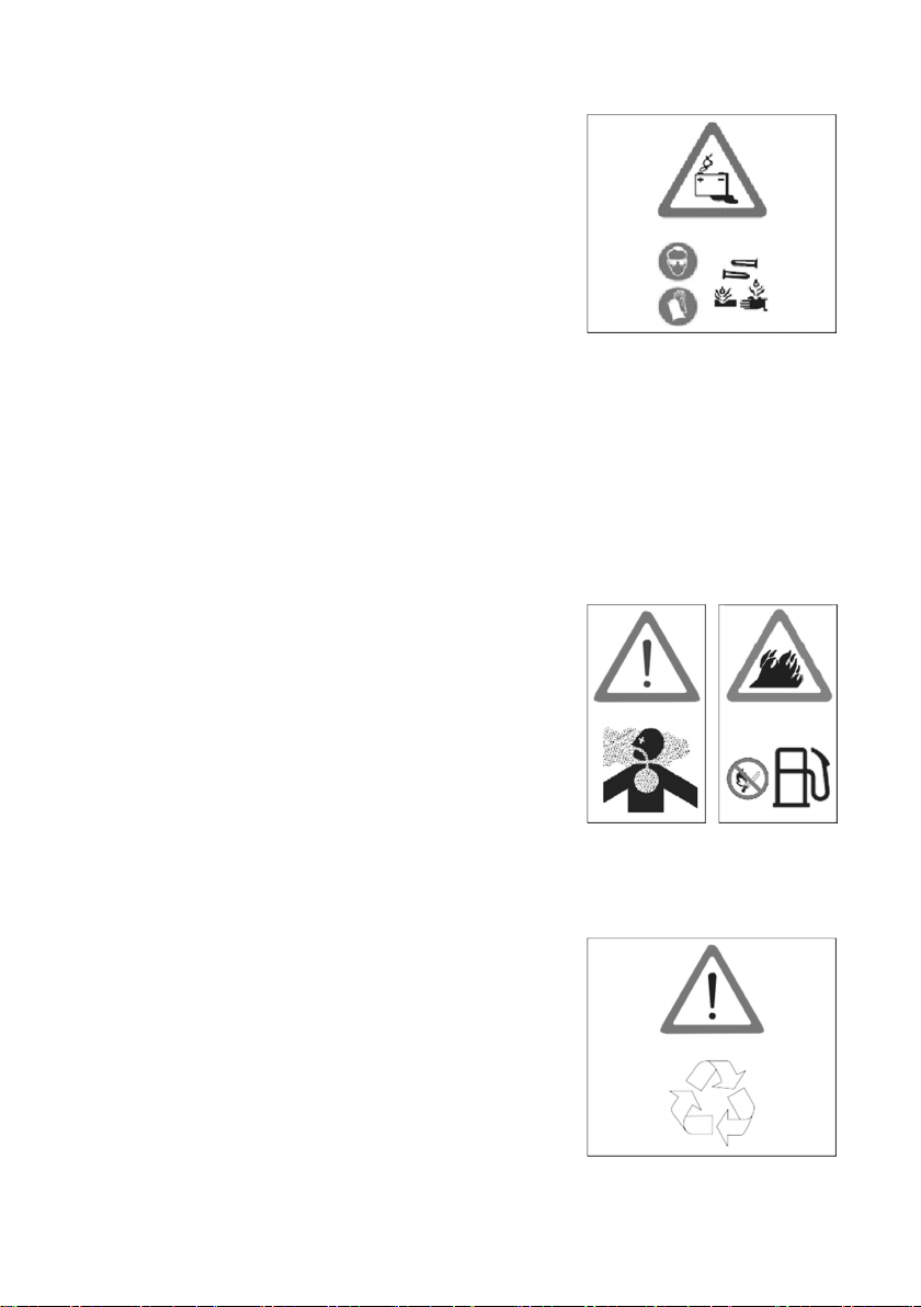
Handling of fuel
Exercise care when handling fuel. Failure to do so
may cause fire.
Do not bring any flames near fuel. Stop the engine
before refueling. Do not smoke while refueling fuel.
Do not refill fuel in an enclosed room. Doing so may
cause an explosion caused by fuel fumes.
If fuel spills, wipe it with a cloth or other material,
and dispose of it according to relevant laws and
regulations.
Disposal
Dispose of disused batteries according to relevant
laws and regulations.
Genuine parts
When replacing parts for servicing and maintenance
of portable fire pumps, be sure to use only Tohatsu
genuine parts.
If genuine Tohatsu parts and accessories are not
used, it may adversely affect the functioning and
safety of the fire pump. Use genuine Tohatsu parts
only.
Tohatsu bears no responsibility for any personal
injuries or equipment damage that may result from
use of parts or accessories obtained from outside
sources.
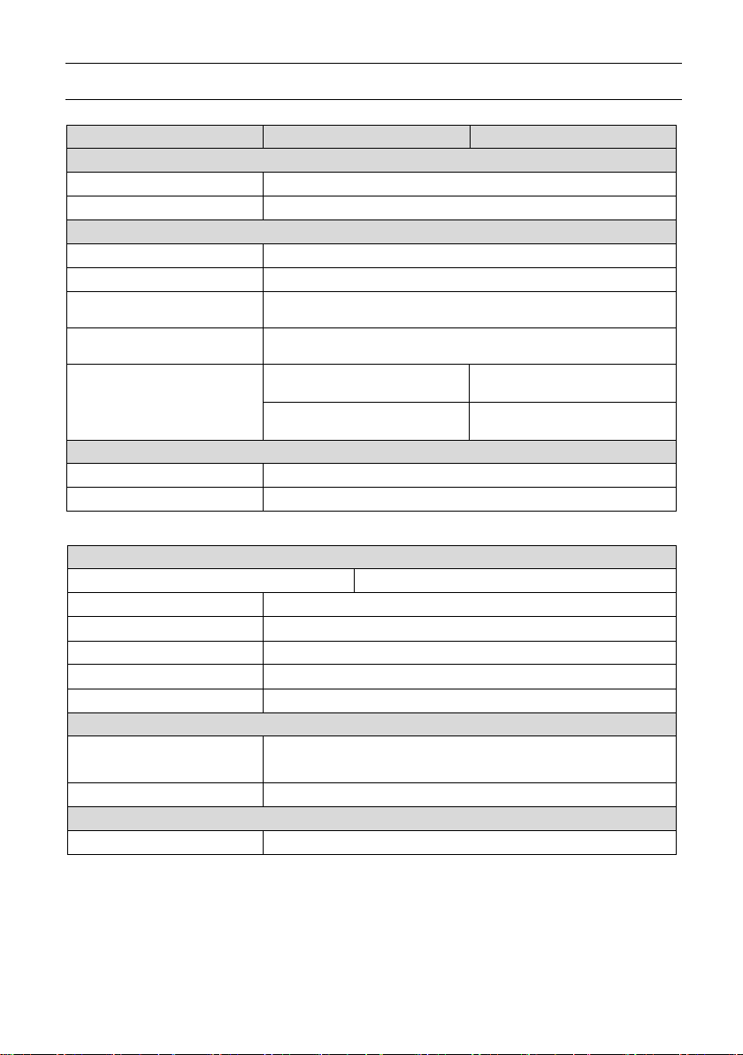
Environmental protection measures
Dispose of oil, fuel, batteries, etc. according to
relevant environmental laws.
Do not dump waste into the ground, water, or
sewerage.
Store the fuel only in the specified container.
When disposing of parts, follow the correct disposal
procedure.
Water-prohibiting substance
Do not discharge water to water-prohibited
substance.
Use of water
Do not pump combustible liquids, chemical or
caustic liquids.

CONTENTS
1. SPECIFICATIONS……..……..….…...…..……….….……….…………..………1
2. OPERATION DEVICE……….….…..………………….…...…..…….…………5
3. LABELS……..….….……….………...…………...………...….…………….….……7
4. OPERATING PRECAUTIONS…………....…........………...……....…..…8
5. DESCRIPTION OF DEVICES……..…....……....….….….…..……….…..10
6. PREPARATION FOR OPERATION……………….…...………….…..…21
7. USE OF OPERATION PANEL…………..………...…..……………………26
8. STARTING THE ENGINE…..……….…...…….…….….…….....……....…29
9. PRIME AND DISCHARGE.……..……….….…………….……..….……..34
10. STOPPING THE ENGINE...……….………….…....…...…..…..….….…...41
11. MAINTENANCE AFTER OPERATION……..……..…..…..……..…...42
12. MAINTENANCE IN COLD CONDITION……...…...….………..….…49
13. USE OF ACCESSORY.……..….…..……………..….….…..….….….….…54
14. PERIODICAL INSPECTION…...……..…………..……........….….……..55
15. SERVICE AND MAINTENANCE….....................…......……...….…..58
16. TROUBLESHOOTING….………..….…..….….......……….….…......……69
17. APPENDIX….…..………..…………..…...…...…..……….……….….……...….83
18. TOOL AND STANDARD ACCESSORY……..…………….………..….84
19. WIRING DIAGRAM……………..……………...….…….….……..…….……..85

1. SPECIFICATION
S
Model
VC52AS
VC72AS
Description
Portable
pump
Engine
Manufacturer
TOHATSU CORPORATION
Model
2WT76AM
Type 2-stroke, water
-
cooled spark ignition engine
Bore ×Stroke
76 mm × 68 mm (2.99 in × 2.68 in)
Number of Cylinder
2
Piston displacement
617 cm
Authorized output
30kW (40.8PS)
Fuel type
Unleaded petrol RON91
Fuel tank capacity
18 L (4.76gal(US))
Fuel
consumption
9 L/h (2.38gal(US)/h)
13 L/h (3.
43
gal(US)/h)
Engine oil tank capacity
1.6 L (0.42gal(US))
Ignition
C.D.I.
Spark plug
NGK BPR7HS
-10
Starting system
Electric starter and Manual starter
Lubrication
Auto mixing
Fuel system
Carburetor
Battery
12V-16 Ah/5 h, 12V
-
18 Ah/10 h
Flooding bulb
12V-35W
3
1
1. SPECIFICATION
S
Model
VC52AS
VC72AS
Primer
Type Rotary
-
vane vacuum pump (Oil less type)
Max. suction height
Approx. 9 m (29.5 ft)
Pump
Type Single suction, single
stage, centrifugal pump
Number of delivery outlet
1
BSP thread 2
-
1/2” (male)
JIS fire thread (B
-
9912) 2
-
1/2” (male)
BSP thread
4”(male), 4
-
1/2" (
male)
JIS fire thread (B
-
9912), 3” (male), 3
-
1/2” (male)
1.45 m
3
/min at 0.5 MPa
1.43 m
3
/min at 0.7 MPa
1.15 m3/min at 0.7 MPa
1.02 m
3
/min at 1.0 MPa
Dimensions and weight
Length×Width×Height
700
× 620 × 730 mm (27.6 × 24.4 × 28.7 in)
Mass (Dry)
85 kg (187 lbs)
Engine
Crankcase, Cylinder, Cylinder head
Aluminum alloy
Crankshaft
Chromium
-
molybdenum steel
Connecting rod
Chromium
-
molybdenum
steel Piston
Aluminum alloy
Pump shaft
Chromium
-
molybdenum steel
Muffler
Steel Pump
Pump casing,
Impeller
Aluminum alloy
Shaft seal
Type Mechanical seal
Discharge port coupling
Suction port coupling
Pump performance
(Suction height: 3 m / 9.8 ft)
Materials
Pump cover
380 gal(US)/min at 75 psi
300 gal(US)/min at 100 psi
Aluminum alloy
375 gal(US)/min at 100 psi
265 gal(US)/min at 150 psi
2
1. SPECIFICATION
S
gal(
US)
/min
MPa
gal(US)/min
1.0
0
.9 0
.8 0
.7 0
.6 0
.5 0
.4 60
80
m3/min
0
.6 0
.7 0
.8 0
.9 1.0 1.1 1.2 1.3 1.4 1.5 400 350 300 250 200
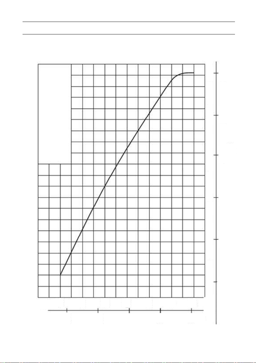
Performance Curve
VC52AS
Suction hose dia. :3’’
Suction hose length :6m
Suction hose height :3m
PERFORMANCE CURVE
psi
Discharge
140
120
100
Pressure
3
1. SPECIFICATION
S
MPa
m3/min
80 100 120 140
0
.8
0
.6
0
.8 0
.9 1.0 1.1 1.2 1.3 1.4 1.5 1.6 1.7 450 400 350 300 250
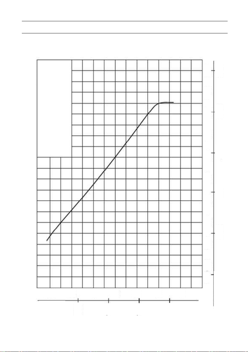
Performance Curve
VC72AS
PERFORMANCE CURVE
Suction hose dia. :3’’
Suction hose length :6m
Suction hose height :3m
psi
Discharge
1.0
0.9
0.7
Pressure
0.5
gal(US)/min
4
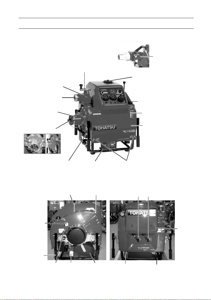
2. OPERATI
O
N DEVICE
Engine oil tank
Battery
Discharge valve
(Ball cock type)
Suction port
Suction hose
coupling (cap)
Carrying
Manual starter
Fuel drain pot
Muffler
Priming outlet
Exhaust pipe
Real
Discharge valve
Discharge port
Fuel cock
Handles(4)
handle
Discharge valve handle
Pump casing drain cock
Priming lever
Primer strainer
Fuel tank cap
Engine oil tank cap
Front cowl
Knob (wing screw)
Spark plug (#1)
Spark plug (#2)
cowl
5
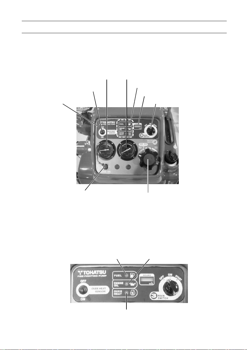
2. OPERATI
O
N DEVICE
Monitor
lamps
Hour meter
Main switch
Control panel
Operation panel warning lamps
Pressure gauge for suction
Overheat switch
Operation panel
Floodlight projection and battery
charging socket
Fuel Engine oil
Pressure gauge for discharge
Throttle dial
Overheat
6
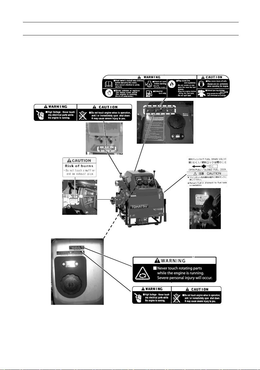
3. LABEL
(Pulley for Vacuum pump)
WARNING & CAUTION
On the fuel tank ~ Inside of the cowl
7

4.
OPERATING PRECAUTION
S
CAUTION
Installing pump
The fire pump must be installed on a level ground. Otherwise, an
accident may occur.
If the fire pump should be installed on uneven ground, it must be
secured.
NOTE
Place the pump as near as possible to water source, and water
suction height as low as possible.
When putting the portable fire pump down to the ground, put it
gently and horizontally.
In case of the inclined location or uneven ground, make sure that
water suction hose is located lower than suction port of the pump.
In case of the suction hose is put undulated, air can be left easily in
the hose, and possibly cause suction inability when the water
discharge valve is opened.
In case of the suction inability due to air remaining in the suction
hose, set the water discharge valve half-opened, and operate
vacuum pump until water is discharged continuously. (for 3 to 5
seconds from beginning of water discharge).
Be sure to install strainer and basket on the end of suction hose. If
the pump may suck sand or mud of the bottom of water source,
place sheet below the basket.
Strainer and basket of suction hose should be placed more than 300
mm (11.8 in) below water surface to prevent suck of air.
Discharge hose should be arranged not to be bent.
8
4.
OPERATING PRECAUTION
S
CAUTION
Do not put your
CAUTION
When installing the portable pump in the vehicle, place the
vehicle on a level place, and install the pump.
When installing the portable pump in the vehicle, make sure to
apply the brakes of the vehicle in order to stop the wheels. A
serious accident may occur if the vehicle moves.
Do not put your hands or fingers in
the retractable part when operating
the handle.
When transporting the portable fire
pump, assign one person per handle.
Also, when you transport the
portable fire pump, it should be
transported holding the handle
firmly.
NOTE
When lowering the portable fire pump
to the ground, lower it gently and
horizontally.
Do not touch the exhaust pipe and the muffler
while the engine is running, or for more than 10
minutes after the engine has been stopped.
These parts are very hot and will cause severe
burns.
hands or fingers
9

5. DESCRIPTION OF DEVICE
S
Carrying handle
Carrying handle
CAUTION
Wing screw
Open
Close
NOTE
Hook
Carrying handle
The fire pump is equipped with four carrying handles.
The handles can be folded manually, and opened by
rotating them by 90 degrees.
Personal injuries may occur when
opening or closing the handle.
Do not put your hands or fingers
into the retractable part when
operating the handle.
To prevent injuries, two persons
should work together when carrying
and placing the pump.
Opening the cowl
Front cowl
When you remove the front cowl, turn the 2 wing screws
at the front cowl and release the lock on each screw.
Release the 2 hooks up at the back side of the pump.
Lift the front cowl toward upper side.
When removing the cowl, do not use
excessive force with care to avoid
damaging the hook, cowl or other
parts.
10
5.
DESCRIPTION OF DEVICE
S
Rear cowl
Plug cap
Pin Hook
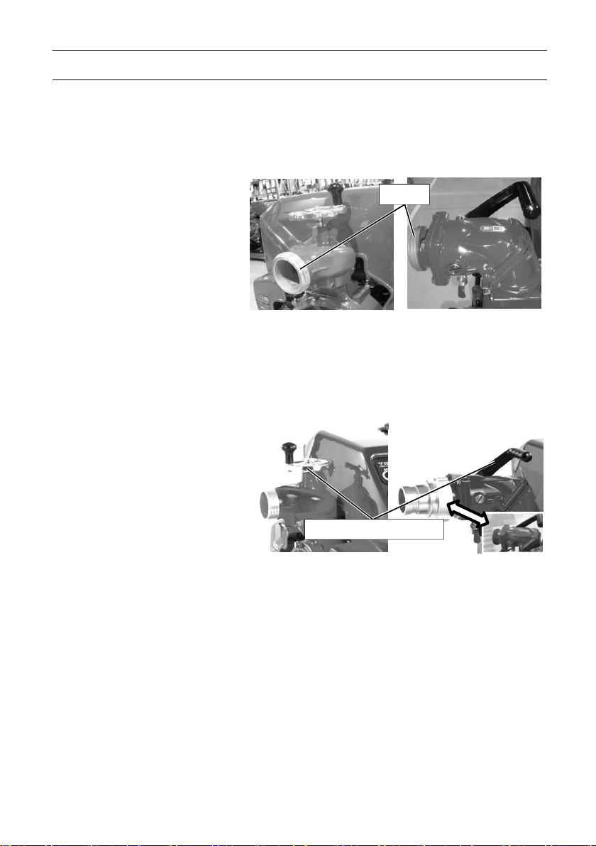
Suction port
CAUTION
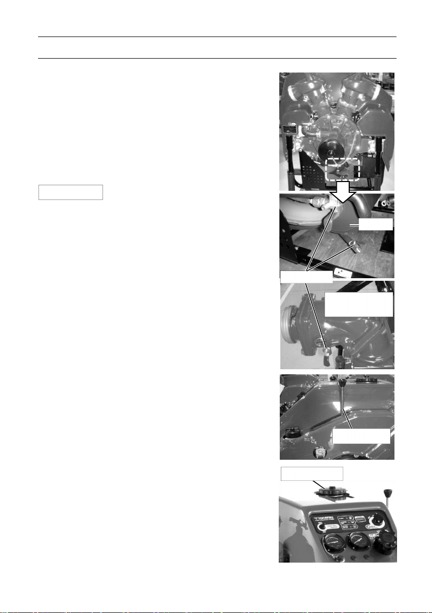
Rear cowl
・ When you remove the rear cowl, detach the two plug
caps from the spark plugs.
・ Pull open the cowl at around the support pin.
・ Remove the plug caps through the holes in the cowl.
・ Lift the rear cowl toward upper side.
NOTE
Assembling the cowl
Assembling order is in reverse order of the opening.
The hooks (at 2 locations on the cowl) must be aligned
to sockets of the grommet before insert firmly.
・ Remove the front cowl first, and the
real cowl second.
NOTE
Suction port
The diameter of the thread for the fire pump is
BSP thread 4” (male), 4-1/2” (male)
JIS fire thread (B-9912), 3” (male), 3-1/2” (male)
・ Assemble the rear cowl first, and the
front cowl second.
・ When the pump is running, do not
put your finger Into the suction port,
you may be seriously injured by the
rotating inducer.
・ If the pump runs without a strainer,
gravel may enter the pump,
resulting in significantly reduced
water discharge capacity.
11
5. DESCRIPTION OF DEVICE
S
Screw down discharge
Ball valve discharge
Thread
Screw down discharge
Ball valve discharge
Discharge valve handle
Discharge port
The diameter of the thread for the fire pump is
BSP thread 2-1/2” (male)
JIS fire thread (B-9912) 2-1/2” (male)
Discharge valve
Use the discharge valve handle for opening and closing the discharge valve.
Valve (Single outlet)
valve (Single outlet)
Valve (Single outlet)
valve (Single outlet)
12
5. DESCRIPTION OF
DEVICE
S
Drain valve
Muffler
Ball cock
Priming
lever Fuel tank cap
Drain valve
Use the drain valves to drain water.
Drain valves;
- at the pump case
- at the muffler
- at the ball cock discharge valves (Only for ball cock
discharge valve type)
NOTE
Priming lever
Use for suctioning water.
After starting the engine, pull down the priming lever to
suction water.
After priming has been completed, return the priming
lever to its original position.
Fuel tank
Refill appropriate amount of gasoline to the fuel tank.
Close the fuel tank cap all the time except refuel.
・ Close all the valves when operating
the fire pump. If the valve is opened,
water cannot be suctioned.
Discharge valve
13
5. DESCRIPTION OF DEVICE
S
Control panel
Operation panel
CAUTION
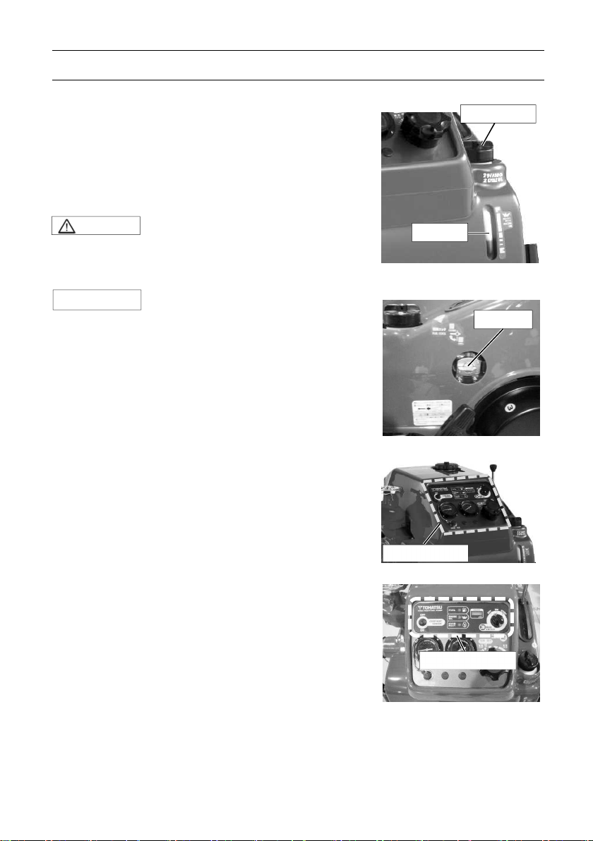
Oil tank cap
Oil tank
Fuel valve
Engine oil tank
Refill appropriate amount of oil to the oil tank.
Close the Oil tank cap all the time except filling.
The oil tank has an oil level sensor.
The warning buzzer sounds, if the engine oil is not
enough filled.
・ If you run the pump despite of the
warning buzzer sounds, the engine
could have damages and/or be
stuck.
NOTE
Fuel valve
Full open or close completely.
Control panel
The control panel is equipped with all the necessary
operating and control instruments as follows.
Operation panel
The operation panel is equipped with
・ Fill the 2-stroke engine oil until the oil
level warning buzzer does not sound.
・ Main switch
・ Warning lamp : Fuel, Oil, Over heat
・ Hour meter
・ Over-heat switch
14
5.
DESCRIPTION OF DEVICE
S
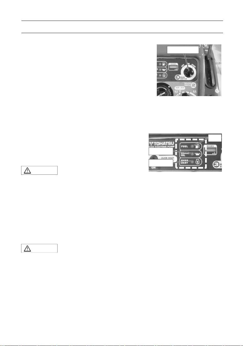
Main switch
Fuel Engine oil
Overheat
Main switch (Stop switch)
Turn the Main switch to run or to stop the pump.
Description Function
OFF To stop the pump
ON Running position
START To start the pump running
Warning lamp and Warning buzzer
Turning the start switch “ON” position, if there is no problem in the engine to start,
the warning lamps and buzzer are off. If there some problems in the pump, the
monitor lamps light on when you turn the start switch on. The warning lamps and the
buzzer indicate the following information:
Warning lamp: Fuel, Engine oil, Overheat
Warning buzzer alarms: Engine oil
CAUTION
-Low fuel level warning
If the fuel level goes down below approximately 1/3 of the fuel tank, monitor lamp
lights up.
・ If they do not, remove the cause
by following the content ”16
troubleshooting” section.
-Low engine oil warning
If the engine oil level goes down below approximately 1/3 of the engine oil tank,
warning lamp lights up and the warning buzzer sound.
CAUTION
・ Refill the engine oil immediately. Even if the warning lamp lights
up and the buzzer sound, the engine will not stop soon.
However, refill the engine oil immediately to avoid the engine
stuck risk.
15
5.
DESCRIPTION OF DEVICE
S
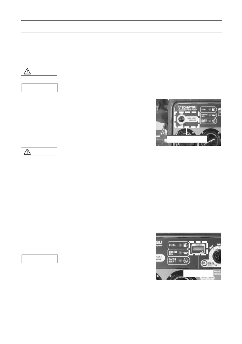
Overheat switch
Hour meter
NOTE
-Overheat warning
If the engine overheat caused by lack of cooling water, etc. then the overheat lamp
lights.
CAUTION
NOTE
Overheat switch
The overheat sensor switch should be always set in “ON”
position to avoid a malfunction or destruction of the
engine by overheating.
CAUTION
In the case of the switch “ON”, the engine will stop, the lamp turns on and buzzer
sound when the overheat sensor works.
In the case of the switch “OFF”, the engine will not stop, the lamp turns on and buzzer
also sound when the overheat sensor works.
The engine can be started if the switch is at “OFF” position.
Hour meter
The hour meter indicates the accumulated operation
time of the fire pump.
・ The engine may be damaged. Do not restart the engine soon after
stopped running.
・ In the case of the overheat sensor switch is set in “ON” position, the
engine stops automatically when an overheated is detected.
・ Restarting without treating with the cause of overheating may
cause the engine condition become worse or be damaged.
In particular, with regard to trouble that occurs in the suction
line, cooling line, fuel line and engine itself, remove the cause
and then restart the engine.
・ Make sure that the warning lamp and the buzzer have turned off.
・ Use it to check the running time.
・ The meter continues counting as long
as main switch is “ON”
16
5.
DESCRIPTION OF DEVICE
S
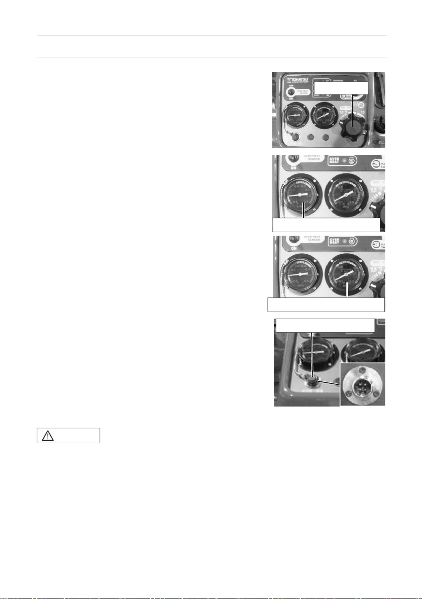
Throttle dial
Pressure gauge for suction
Pressure gauge for discharge
Battery charger socket
Throttle dial
Use the Throttle dial to control discharge pressure.
Pressure gauge for suction
The pressure gauge for suction indicates the actual
operating pressure.
Pressure gauge for discharge
The pressure gauge for discharge indicates the actual
operating pressure.
Battery charger socket
Connect the battery charger plug to the socket when
charging the battery of the pump.
<Specifications of accessory socket>
・ Voltage: DC12V
・ Max. allowable current: 5A
CAUTION
・ Before charging a battery, turn the main switch OFF.
・ When starting operation, make sure to remove the battery
charger before turning the main switch ON.
・ The socket is for a battery and a floodlight.
・ Do not connect a cigarette lighter to the socket, because it is not
a heat-resistant object.
17
 Loading...