

TOHATSU TLDI 40, TLDI 50 Service Manual
SERVICE MANUAL
OIL
WASH
OILLEVEL
B

Chapter 1 Specifications
1. Specifications Table ......................................................................1-3
2. Outline Dimensions .......................................................................1-4
3. Background on TLDI......................................................................1-6
1

1-2
1-3
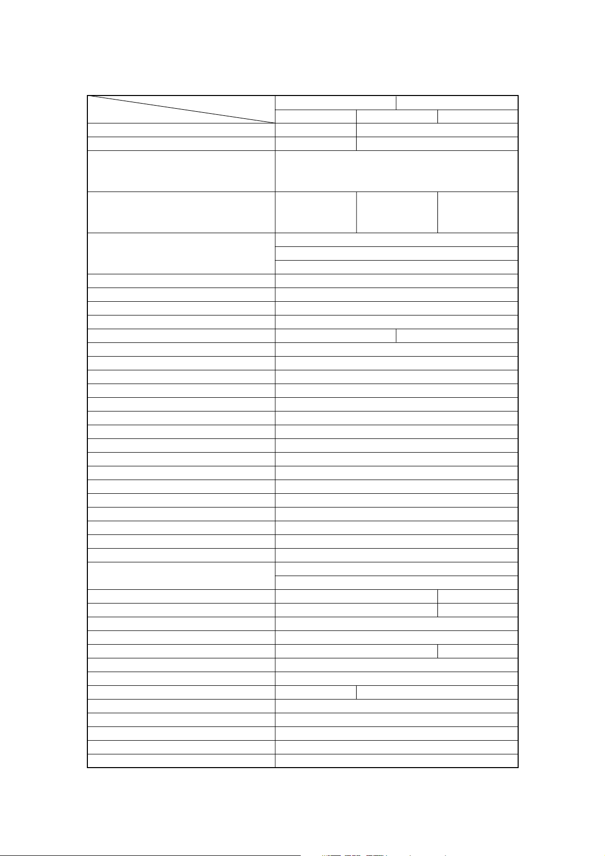
1. Specifications Table
MODEL
40A 50A
Item
EPTO EFTO EFO
Overall length (approx.) 630 mm (24.8 in) 1120 mm (44.1 in)
Overall width (approx.) 345 mm (13.6 in) 384 mm (15.1 in)
Transom (S) 1227 mm (48.3 in)
Overall height
Transom (L) 1354 mm (53.3 in)
(approx.)
Transom (UL) 1481 mm (58.3 in)
Transom (S) 95.5 kg (211 lb) 98.5 kg (217 lb) 88.5 kg (195 lb)
Weight
Transom (L) 96.5 kg (213 lb) 99.5 kg (219 lb) 89.5 kg (197 lb)
(approx.)
Transom (UL) 99.0 kg (218 lb) 102.0 kg (225 lb) 92.0 kg (203 lb)
Transom (S) 403 mm (15.9 in)
Transom length
Transom (L) 530 mm (20.9 in)
(outboard)
Transom (UL) 657 mm (25.9 in)
Engine type 3-cylinder inline
Piston displacement 697ml (42.5 cu.in)
Bore & stroke 68 mm (2.68 in) x 64 mm (2.52 in)
No. of cylinders 3
Maximum output 29.4 kW 36.8 kW
Full-throttle range 5150~5850 rpm
Trolling 700 rpm
Idling 700 rpm
Full-throttle fuel consumption (approx.) 17 L/Hr (4.5 US gal/Hr)
Starting system Electric starter motor
Intake system Reed valve
Scavenging system 5-port loop
Exhaust system Through hub
Lubrication system Auto-mixing
Cooling system Forced water-cooling
Water temp. control Thermostat
Ignition system L-CDI
Ignition timing control Electronically advanced
Firing order 1-2-3
Sparkplug Champion RC10ECC
Alternator 12V 280W
Battery
12V 100AH
12V 120AH (0°C or low)
Trim angle 8°~24° 4°~24°
Trim angle settings 5 6
Maximum tilt-up angle 75°
Transom board thickness 31~70 mm (1.22 ~ 2.76 in)
Maximum steering angle 70° 80°
Gear shift Dog clutch (F-N-R)
Gear ratio 1.85 : 1 (13 : 24)
Throttle control Remote-control Tiller handle
Fuel tank 25L (6.60 US gal)
Oil tank 2L (2.1 US qt)
Fuel Unleaded regular gasoline
Engine oil Genuine engine oil or TC-W, 2-stroke marine outboard oil*
Gear oil Genuine gear oil (500 ml) or API GL5, SAE #80
*: Only those products that have been approved.
1-4
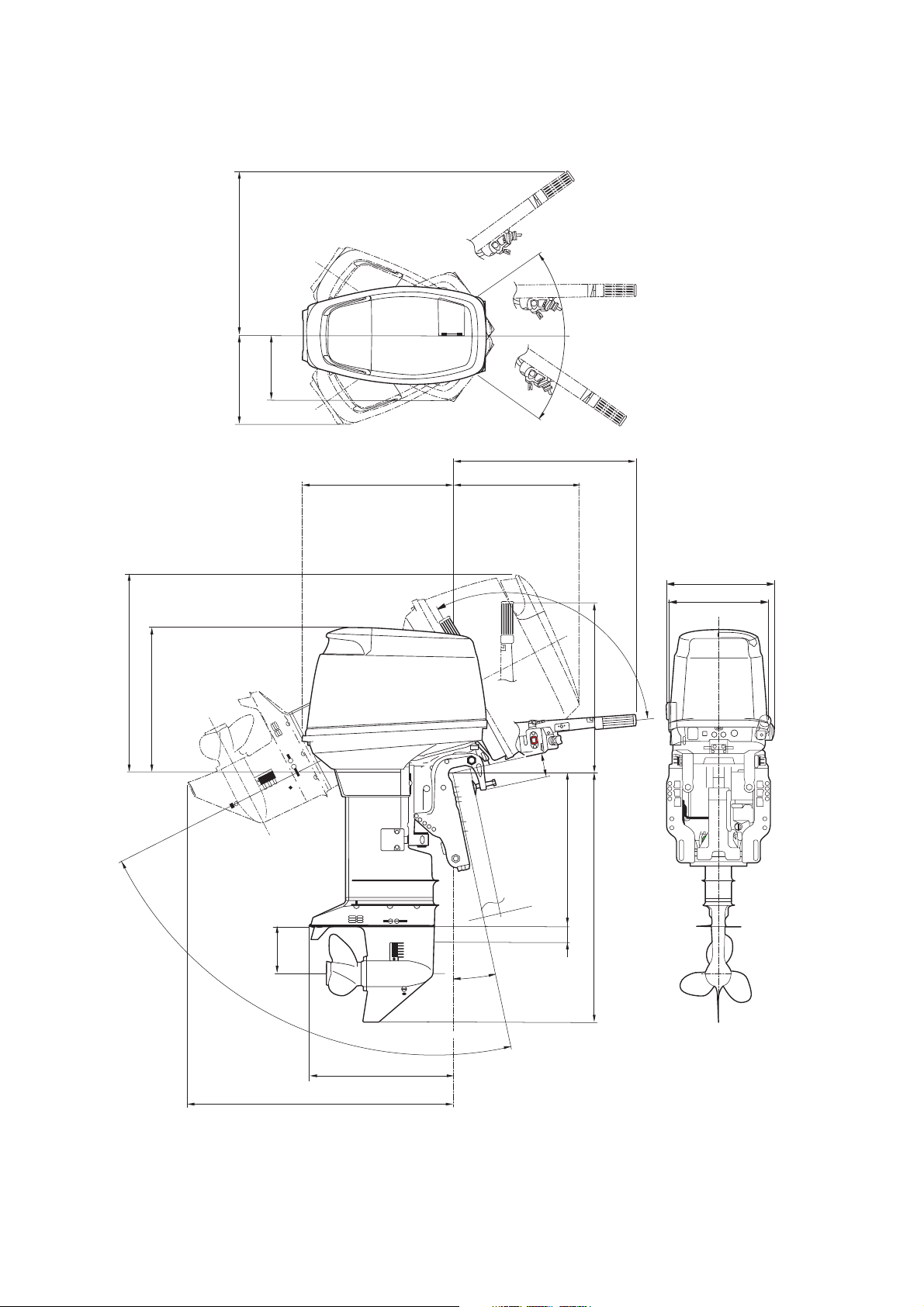
2. Outline Dimensions
M 1
M 2
P
N
O
S
G
HI
Q
D
F
C
B
J
Y
R
U
L
K
T
A
E
S

1-5
External Dimensions
Item Remarks
A 499 mm (19.6 in)
Transom (S) 728 mm (28.7 in)
B Transom (L) 855 mm (33.7 in)
Transom (UL) 982 mm (38.7 in)
Transom (S) 403 mm (15.9 in)
C Transom (L) 530 mm (20.9 in)
Transom (UL) 657 mm (25.9 in)
D 568 mm (22.4 in) Models EFTO, EFO
E 680 mm (26.8 in)
F 85 mm (3.3 in)
G 623 mm (24.5 in) Models EFTO, EFO
H 520 mm (20.5 in)
I 440 mm (17.3 in)
J 30-75 mm (1.2~3.0 in)
K 490 mm (19.3 in)
Transom (S) 800 mm (31.5 in)
L Transom (L) 910 mm (35.8 in)
Transom (UL) 1025 mm (40.4 in)
M1 384 mm (15.1 in) Models EFTO, EFO
M2 345 mm (13.6 in) Model EPTO
N 310 mm (12.2 in)
O 235 mm (9.3 in)
P 565 mm (22.2 in) Models EFTO, EFO
Q 120deg. Models EFTO, EFO
R 12deg.
S 35deg.
T 75deg.
U 161 mm (6.3 in)
Y 54 mm (2.1 in)
3. Background on TLDI
The abbreviation TLDI stands for Two-stroke Low-pressure Direct Injection and
is the name Tohatsu applies to direct fuel-injection system engines.
1. Two-Stroke Low-Pressure Direct Injection (TLDI)
TLDI is the name Tohatsu uses for two-stroke engines that utilize the air-assisted, low-pressure direct
injection system.
The air-assisted, low-pressure direct injection system has been combined with the L-CDI or (Long-arc
duration CDI ignition system and Engine Control Unit (ECU), which performs precision control of fuel
mixture, injection timing and ignition timing to maximize combustion efficiency in the TLDI-50 engine.
The result is better fuel economy, smaller size and greater power in a two-stroke engine.
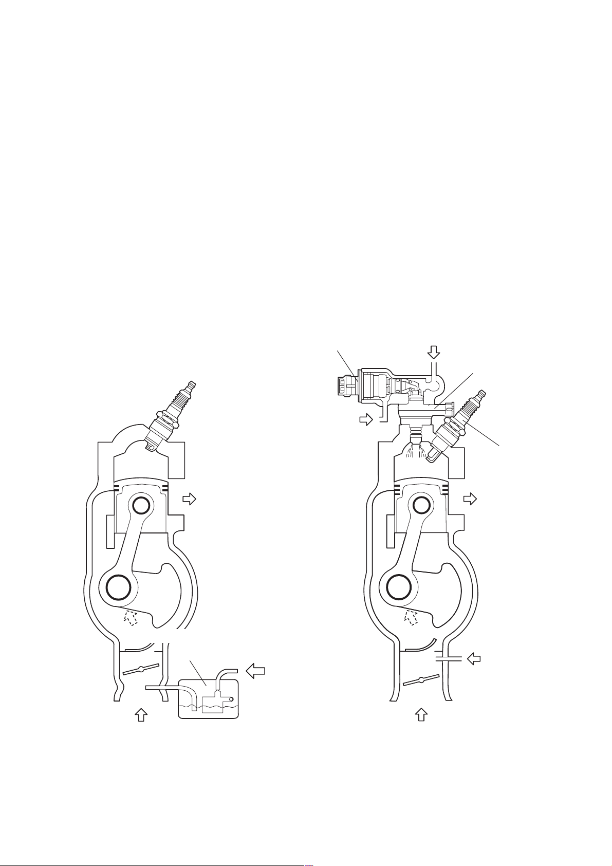
2. Air-Assisted Low-Pressure Direct Injection
With TLDI, the air-assisted, low-pressure direct injection process involves using an air compressor to
pressurize the fuel supplied by the fuel pump to in order to propel or inject it directly into combustion
chambers in the form of a finely atomized mixture to achieve maximum combustion efficiency.
CARBURETOR TLDI
Compressed air
Pressurized fuel
ExhaustExhaust
Oil
Air
AirAir
Gasoline + Oil
Atomized fuel mixture
r
q
e
w
1-6
q Fuel injector
w Air injector
e Spark plug
r Carburetor
1-7
3. ECU Control
With TLDI, a network of connected sensors enables the Engine Control Unit (ECU) to precisely
regulates fuel mixture injection rate and ignition timing. The ECU also uses a stratified fuel feed process
to provide lean combustion in the low-speed range, while utilizing more homogenized change to ensure
the fuel mixture is distributed uniformly throughout the combustion chamber when operating in the high-
speed range to ensure maximum combustion efficiency.
L-CDI charge coil
Crank-position sensor
(CPS)
Throttle-position sensor
(TPS)
Water-temperature sensor
(WTS)
Oil level sensor
Battery
Key switch
Stop switch
#1, #2 & #3
Fuel injectors
#1, #2 & #3
Air injectors
#1, #2 & #3
Ignition coils
Tachometer
Warning indicators
Warning horn
Fuel-feed pump
(FFP)
Engine Control Unit
(ECU)
➞
➞
➞
➞
➞
➞
➞
➞
➞
➞
➞
➞
➞
➞
➞

Long-duration CDI (L-CDI)
The L-CDI or Long-arc duration CDI ignition system is used as the TLDI ignition system to maximize
combustion efficiency, fuel economy and minimize exhaust emissions. The L-CDI system offers a longer
plug sparking interval, via spark plug, than used with conventional two-stroke engines. This is designed to
ensure more complete combustion of the mixture in the chamber. L-CDI minimizes mis-firing and reduces
fluctuation in engine speed during idling to offer a much smoother engine feel when compared with
conventional two-stroke engines.
Throttle-Position Sensor (TPS)
The throttle-position sensor system is comprised of TPS1 and TPS2. These are used in combination to
detect throttle butterfly valve, position advancer arm position, and to relay the information to the ECU.
Crank-Position Sensor (CPS)
The crank-position sensor is designed to sense the encoder located above the ring gear on the flywheel in
order to detect crankshaft position and transmit the information to the ECU.
Water-Temperature Sensor (WTS)
Positioned on the water jacket installed on the cylinder, the water-temperature sensor (WTS) is used detect
temperature of the cooling water in the cylinder and relay the information to the ECU.
Oil Level Sensor
The oil level sensor is used to detect the level of remaining oil and relay the information to the ECU.
The oil level sensor operates by lighting the indicator on the tachometer and sounding the beeper when
engine oil is low.
Air Injectors
The air injectors are used to inject a fine mist of fuel and air into the combustion chamber for each piston.
The ECU determines the mixture and timing for injecting fuel according to current engine operating
conditions based on information relayed from the various sensors.
Fuel Injector
The fuel injectors supply the fuel in the air rail to the air injectors via the set pieces. The ECU determines the
mixture for injecting fuel according to current engine operation based on information relayed from the
various sensors.
1-8
1-9
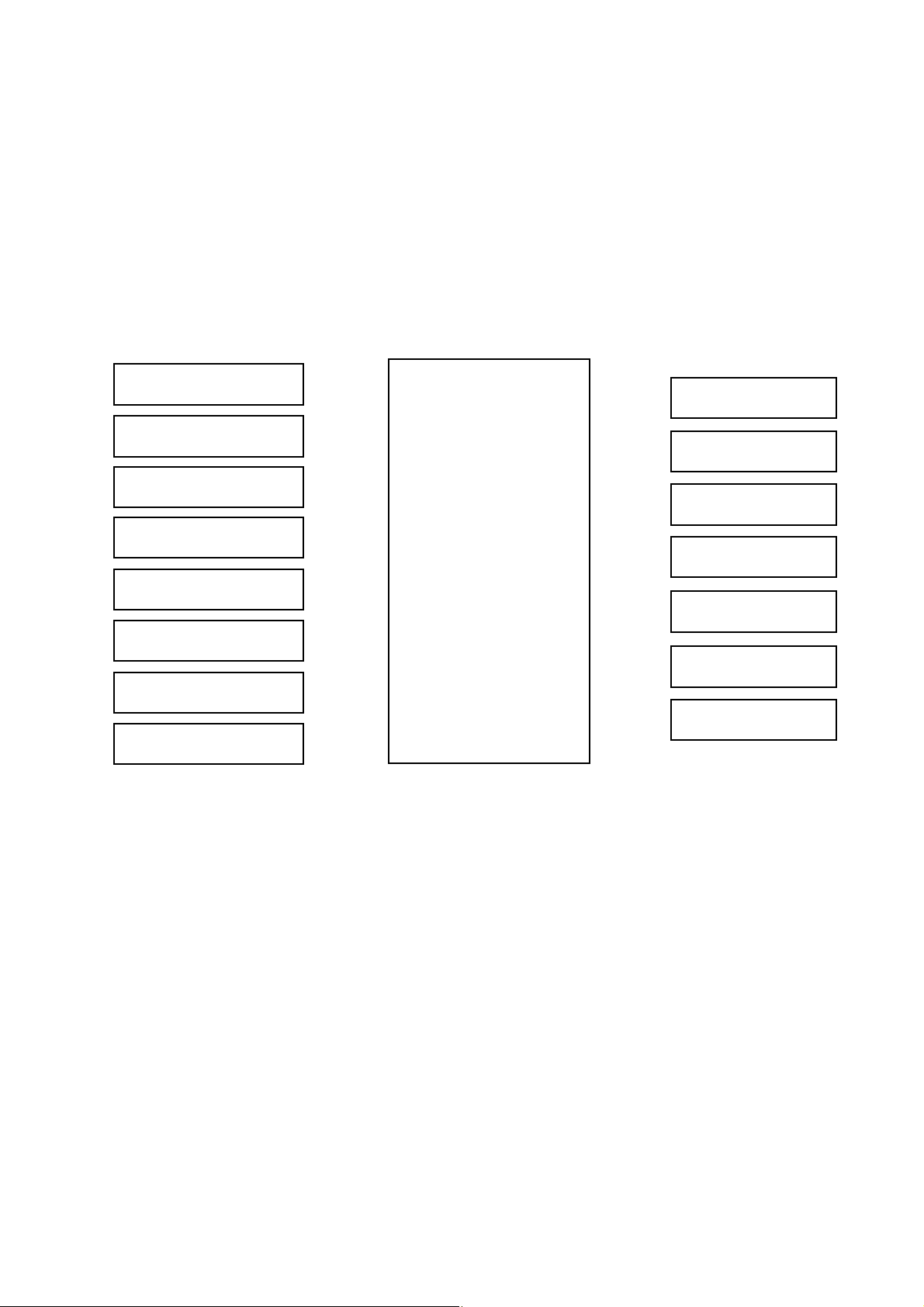
4. Fuel Supply System
!0
IN
O
U
T
Starting the engine activates the fuel pump e, which draws
gasoline from the fuel tank q and routes it through the fuel filter
w to the vapor separator r. The gasoline is pressurized in the
fuel-feed pump FFP t; then passes through the high-pressure
filter y to the air rail u, from there it is injected into the
combustion chambers. The fuel regulator i regulates
components t through u in order to maintain gasoline at a
differential pressure of 80 kPa (11.4 psi). Any excess gasoline is
depressurized and diverted through the FFP case o and back to
the vapor separator r. The returned gasoline contains air
bubbles left over from being pressurized at t. These bleed from
the top of the vapor separator r to the throttle body !0 and is
fed to the air intake system.
q
o
t
r
u
i
w
e
y
1-10
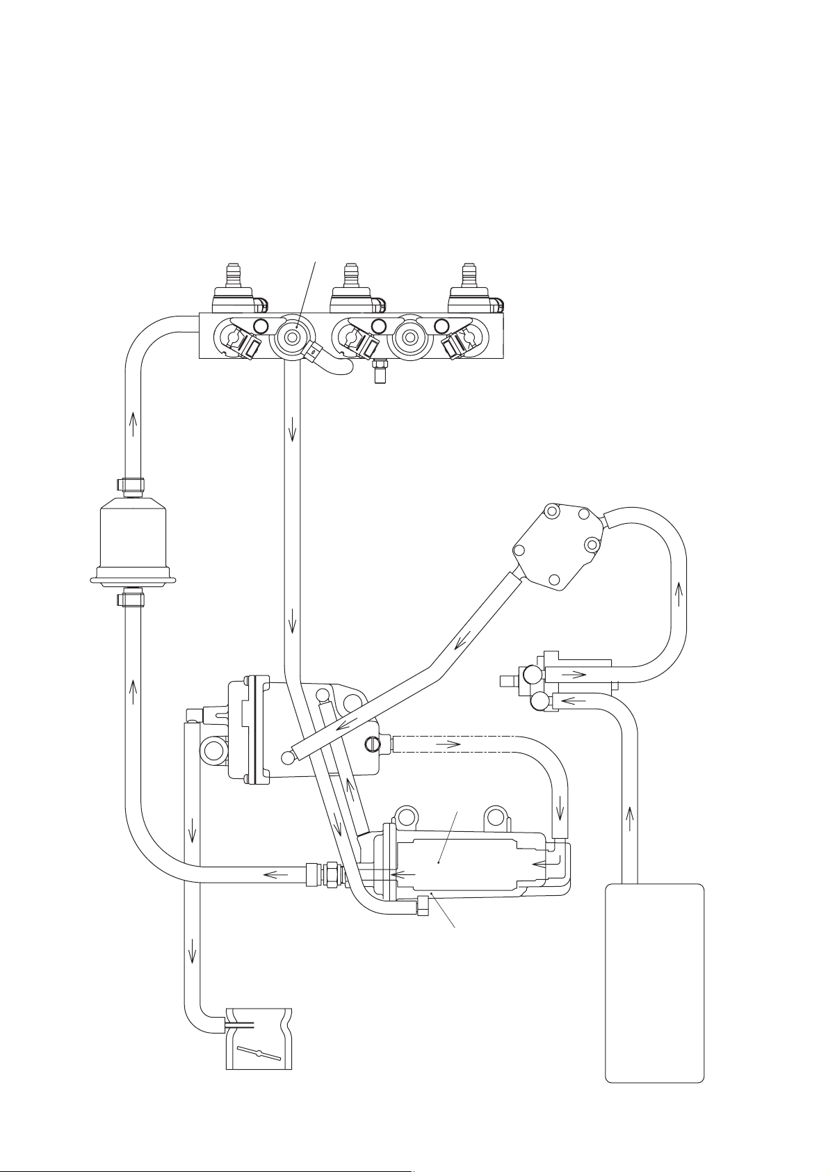
5. Air Supply System
e
r
q
t
w
Starting the engine operates the air compressor
w, draws air in through the air filter q and
sends compressed air through to the air rail e.
From there, the air is drawn in through the air
filter q and used as the air intake when injecting
the pressurized gasoline into the combustion
chamber pressurized by the air compressor w.
The air regulator r regulates components w
and e in order to maintain air at the optimum
combustion pressure of 550 kPa (79.8 psi). Any
excess air is depressurized and sent to the
exhaust t and discharged from the bottom of
the cylinder.
Exhaust
Intake
1-11
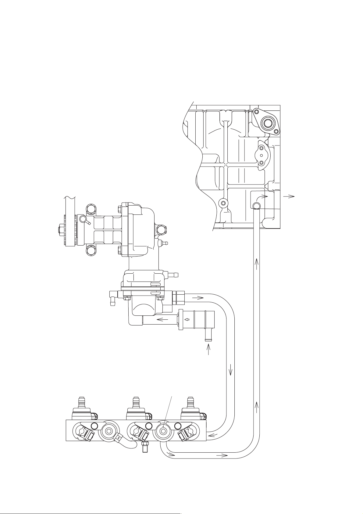
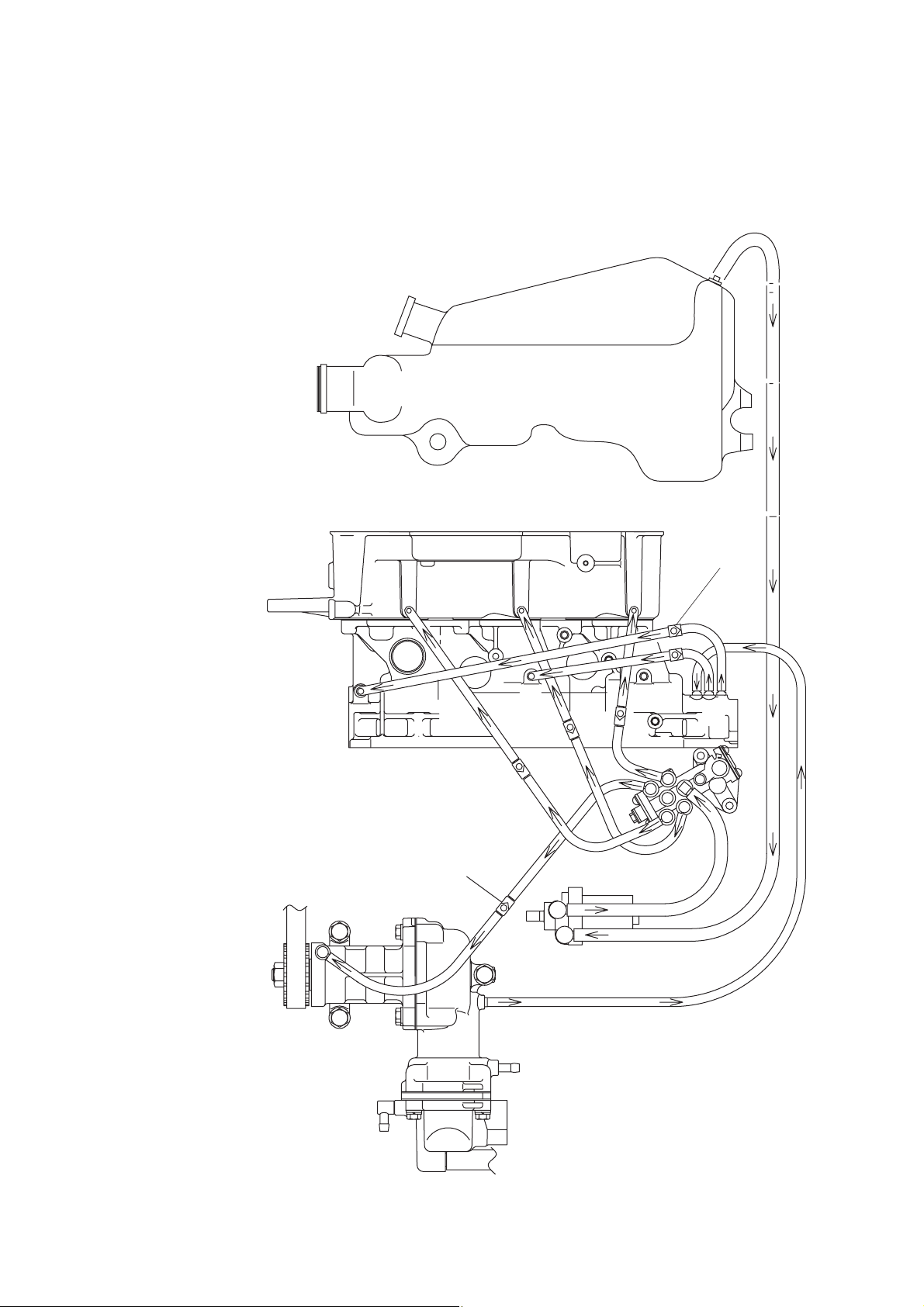
6. Oil Supply System
Starting the engine operates the oil pump q, which draws oil from
the oil tank w and routes it through the oil filter e to the oil pump q.
The oil pump channels the oil through four ports to #1 air box r, #2
air box t, #3 air box y and the air compressor u. Ports r, t and
y serve to lubricate the engine’s pistons, while port (7) lubricates
the air compressor.
TLDI includes a recirculation system in which the excess oil from the
air compressor u is diverted to #3 crankcase i for use in
lubricating the drive gear q. Any oil left over from there is diverted to
#1 crankcase o and the crankcase !0 where it is added to oil from
r and t and reused to lubricate the engine.
q
w
e
r
t
y
u
i
o
!0
Check valve
Check valve

1-12

Chapter 2 Servicing Information
1. General Precautions for Servicing...............................................2-3
2. Specifications and Standards Used in Servicing .......................2-4
3.
Lists of Points for Applying Sealant, Adhesive and Lubrication
.........2-10
4. Torque Table.................................................................................2-16
5. Special Tools................................................................................2-17
2

2-2

2-3
1. General Precautions for Servicing
Users of this manual should observe the following general precautions when
conducting disassembly and assembly work.
(1) Make sure that the outboard motor is securely mounted on a work stand before starting work.
(2) Take care not to scratch or damage painted surfaces and the mating surfaces where cylinders, the
cylinder head, the crankcase and other parts are joined.
(3) Always replace packing, gaskets, O-rings and split pins with new ones when reassembling engine parts.
Make a point of replacing snap rings as well.
(4) When replacing, be sure to use genuine Tohatsu brand parts and lubricants or products recommended
by Tohatsu.
(5) Always use the recommended special tools to ensure work is done properly.
(6) When disassembling and assembling components, make note of position marks, adding your own
marks if none are provided, as a way to ensure the various parts and components are properly mated
when being reassembled.
(7) To prevent smaller parts, such as bolts, nuts and washers from getting lost or damaged, where possible,
lightly insert or tighten them back in their original locations.
(8) As normal practice, check disassembled parts for any wear or damage by first wiping them clean; then
washing them in solvent.
(9) With reassembly operations it is essential to observe precise detail in centering, vacuum sealing,
lubricating (with oil or grease), packing parts and components, and connecting wiring and piping. Also
ensure there are no blockages in fluid lines.
1) When reassembling parts requiring numerous nuts and bolts (cylinder, crankcase etc.), begin by
alternately tightening diagonally opposed inner bolts, moving in a concentric circle; then tightening
the outer bolts. This will ensure that engine parts are assembled evenly and securely. (Use the
same procedure in the reverse order when disassembling.)
2) When installing oil seals, be careful not to scratch or reverse the sides that mate with the shaft and
always apply grease to the lip surfaces.
3) Confirm the correct quantity and thickness when applying sealant. Applying excessively will result in
the excess portion being excreted into or outside of the case, potentially causing damage. Adhere
strictly to the written instructions when applying adhesives.
4) Apply penetrating oil spray to nuts or bolts that are difficult to remove due to rust and wait 5 minutes
before removing.
5) For the various inspection specifications, torque values, special tools, and the points where sealant,
adhesive and grease are to be applied, refer to the relevant tables.
6) The various nuts, bolts and washers referred to in this manual are listed below.
Name Type Diameter Length
H820 Hexagon bolt 8 mm 20 mm
N8 Hexagon Nut 8 mm
L8 Hexagon Nut 8 mm
W8 Plain washer 8 mm
SW8 Spring washer 8 mm
Screw 620 Pan head screw 6 mm 20 mm
(10) Observe all necessary safety procedures to prevent accidents and injury during work operations.

2. Specifications and Standards Used in Servicing
Name of Part Item to check Standard values
•67.96 mm (2.676 in)
Piston
•Top: 0.22 to 0.37 mm
(0.009 to 0.0145 in)
Piston ring •
Second and third: 0.33 to 0.48 mm
(0.013 to 0.019 in)
•0.05 mm (0.002 in)
Crankshaft
Connecting rod • Deflection
• Mating surface •0.03 mm (0.0012 in) or less for
scratches
Cylinder head •0.03 mm (0.0012 in) or less for
distortion
• Mating surface •0.03 mm (0.0012 in) or less for
scratches
•0.03 mm (0.0012 in) or less for
Cylinder
distortion
• Cylinder liner scratches and wear
•0.83 MPa (8.5 kg/cm2, 120 psi)
Engine block
Reed valve stopper • Lift height • 9.3 to 9.5 mm (0.366 to 0.374 in)
• Fails to close, is worn or damaged
Reed valve
•1.1Ω ±15% (Ambient temperature)
Ignition coil
•
12.5 kΩ ±15% (Ambient temperature)
ECU
• Low-speed ESG trigger •Approx. 3,000 rpm
• High-speed ESG trigger •Approx. 6,000 rpm
2-4
• Ring end gap
Note: If a ring gauge is unavailable,
measure the lower end of the
cylinder bore.
• Deflection
Measure with both ends supported on V
blocks.
• Compression
Measure after warming:
Remove all 3 spark plugs.
Remove air injector and fuel injector
connectors.
• Primary coil resistance (between black
& white and orange lines)
• Secondary coil resistance (between
high tension core and B line)
• Outer diameter
Measure at a point 12 mm (0.47 in)
above the lower edge of the piston skirt.

2-5
Service limit Servicing procedure
• 0.8 mm (0.031 in) or more
• 0.9 mm (0.035 in) or more
• 0.05 mm (0.002 in) or more
• Replace with new crankshaft.
• 2 mm (0.08 in) or more • Replace with new crankshaft assembly.
• Repair by polishing the surface plate, starting
with #240 to #400 grit sandpaper and finishing
with #600 grit sandpaper.
• Repair by polishing the surface plate, starting
with #240 to #400 grit sandpaper and finishing
with #600 grit sandpaper.
• Bore and hone to ø68.55 (2.699 in) + 0 to 0.02
mm (0 to 0.0008 in). Check ports and grind if
necessary.
Use oversize pistons and piston rings.
1) When difference in compression between
cylinders exceeds 0.1 MPa
(1.05 kg/cm
2
, 14.5 psi)
2) When abnormally higher than standard value 2) Remove carbon from piston crown and cylinder
head surfaces and clean exhaust gas bypass
valve.
• No longer conforms to standard value • Replace with new part.
• Valve reed fails to close
• Excessive wear on valve seat • Replace entire valve assembly.
• Valve is damaged
1) Bore and hone to ø68.55 (2.699 in) + 0 to 0.02
mm (0 to 0.0008 in). Check ports and grind if
necessary.
Use oversize pistons and piston rings.
• When the cylinder liner cannot be repaired using
#400 to #600 sandpaper due to excessive
scratching or scoring or when the difference
between the maximum and minimum points of
wear in liner bore is 0.06 mm (0.0024 in) or more
• Replace with new piston ring if cylinder liner
wear has not yet exceeded the repair limit.
• Scratch depth or distortion is 0.03 mm
(0.0012 in) or more
• Scratch depth or distortion is 0.03 mm
(0.0012 in) or more

Name of Part Item to check Standard values
Magneto
Spark plug
Crank-position
sensor (CPS)
Thermostat
Fuse
Pump impeller
Pump case liner
Guide plate
Propeller shaft
Drive shaft
Starter motor
Anode
Oil seals
2-6
• Sparking performance
Measured using spark tester
• Sparking order
• Alternator (max.)
• Charging performance
• Exciter coil resistance value (low-speed)
(W/R wire to W/L wire)
• Exciter coil resistance value (high-speed)
(Green wire to W/Y wire)
• Lighting coil resistance value
(Y to Y wire)
• Standard plug
• Plug gap
• Gap with encoder ring (flywheel)
• Pickup coil resistance value
(L wire to G wire)
• Opening and closing of thermostat valve
• Capacity
• Wear and cracks
• Damage to bearing
• Wear on lip of oil seal
• Damage to bearing
• Shaft run-out
• Wear on lip of oil seal
• Battery
• Output
• Brush length (wear limit)
• Commutator under-cut (wear limit)
• Commutator diameter (wear limit)
• Corrosion
• 10 mm (0.39 in) or more at
350 rpm
• #1 ⇒ #2 ⇒ #3
• 280 W
• 1,500 rpm12V 16.5A
• 5,500 rpm12V 18.5A
• 515Ω ±15%
(Ambient temperature)
• 71.8Ω ±15%
(Ambient temperature)
• 0.38Ω ±15%
(Ambient temperature)
• CHAMPION: RC10ECC
•1.0 to 1.1 mm (0.039 to 0.043 in)
•0.5 to 0.9 mm (0.019 to 0.035 in)
• 0.531Ω ± 15%
(Ambient temperature)
• Valve start temperature:
52°C (125.6°F)
• Valve full-open temperature:
65°C (149.0°F)
• Valve full-open lift:
3 mm (0.12 in) or more
• 15A × 2, 30A × 1
• 0.3 mm (0.012 in) or less (Using
both center holes for reference)
• 12V, 100AH-120AH
• 12V to 0.6 kW
• 12.5 mm (9.5 mm)
0.49 in (0.37 in)
• 0.5 to 0.8 mm (0.2 mm)
0.02 to 0.03 in (0.01 in)
• 30 mm (29 mm)
1.18 in (1.14 in)

2-7
Service limit Servicing procedure
1) 1.2 mm (0.047 in) or more 1) Repair so that plugs conform to standard values.
2) When electrodes show excessive wear 2) Replace with new spark plug.
• When sensor no longer conforms to standard • Repair so that sensor conforms to standard value.
value
• When fuse burns out • Replace with new fuse.
• When the tips, and upper and lower surface
lip areas show wear, cracks or damage • Replace with new assembly.
• When depth of wear is 0.1 mm (0.004 in) or more • Replace with new shaft.
• Replace with new shaft.
• 0.4 mm (0.016 in) or more • Repair so that shaft conforms to standard values.
• When depth of wear is 0.1 mm (0.004 in) or more • Replace with new shaft.
• Replace with new starter motor.
• When anode shows excessive corrosion • Replace with new anode.
• When lip area shows deterioration, heat
discoloration or damage or when wear • Replace with new oil seal.
reduces interference to 0.5 mm (0.02 in) or less
Name of Part Item to check Standard values
Power trim and tilt
Air compressor
Vapor separator
FFP
Air rail
Air regulator
Fuel regulator
Air injector
Fuel injector
TPS
Water temp sensor • Measured value for resistance • 2.45kW±10% (20°C, 68°F),
0.32kW±10% (80°C, 176°F)
Oil level sensor • Conductivity
Rectifiers
• Conductivity Refer to tester checkpoint Table
(Chapter 5).
2-8
Pump assembly:
• Relief valve opening pressure
• Spool check valve opening pressure
• Oil quantity
• Oil type
• Oil filter
Tilt cylinder:
• Shock absorber valve opening pressure
• Piston diameter
• Piston rod diameter
• Stroke
Motor:
• Rated timing
• Rated voltage
• Output
• Direction of rotation
• Cylinder bore
• Piston diameter
Measure at a point 10 mm above the
lower edge of the piston skirt.
• Piston ring end gap
• Reed valve tip clearance
• Drive belt
• Wear and damage on seal ring
• Float
• Wear and damage on seals and
grommets
• Wear and damage on O-rings
• Air pressure
• Fuel pressure
• Measured value for resistance
•
Operating condition (check for clicking sound
when 12 volts is applied to the terminal)
• Measured value for resistance
• Measured values of resistance between
connectors.
• Tilted up: 13.7 to 16.7 MPa
(140 to 170 kg/cm2) (1987 to 2421 psi)
• Tilted down: 2.0 to 3.3 MPa
(2.0 to 34 kg/cm2) (290 to 479 psi)
• Upper chest: 0.24 MPa
(2.4 kg/cm
2
) (348 psi)
• Lower chest: 0.12 MPa
(1.2 kg/cm
2
) (17 psi)
• 550 ml (18.6 US fl. oz)
• Power Torque fluid
(ATF Dexron III or equivalent
product)
• 150 mesh
• 3.4 to 5.4 MPa
(35 to 55 kg/cm
2
) (493 to 783 psi)
• 54 mm (2.13 in)
• 16 mm (0.63 in)
• 141 mm (5.55 in)
• 60sec.
• 12V (DC)
• 650W
• Forward/reverse
•
39.00 to 39.02 mm (1.53 to 1.54 in)
•
38.97 to 38.99 mm (1.534 to 1.535 in)
• Top: 0.10 to 0.25 mm
(0.004 to 0.098 in)
•Second: 0.10 to 0.25 mm
(0.004 to 0.098 in)
•Oil: 0.10 to 0.60 mm
(0.004 to 0.023 in)
• 0.2 mm (0.008 in) or less
•0.55 MPa (5.6 kgf/cm
2
) ±7%
(80 psi
±7%
)
• Measured air pressure
+ 0.07 MPa (0.7 kgf/cm
2
) ±10%
(10 psi
± 10%
)
•1.3 ±0.3Ω (Ambient temperature)
•
1.8 ± 0.1Ω (Ambient temperature)
•
Between upper and lower
connectors: 5.0Ω ±20%
•
Between upper and middle
connectors: resistance value (kΩ)
Fully closed
Full open
TPS1 4 to 5 0.5 to 1
TPS2 4 to 5 4 to 5

Service limit Servicing procedure
• When parts no longer conform to standard values • Replace with new parts.
• When parts show excessive wear or damage
• When parts show excessive wear or damage
• When parts showed deterioration or contamination • Replace with new parts.
by fuel
• When parts show excessive wear or damage • Replace with new parts.
• When parts show excessive wear or damage • Replace with new parts.
• When parts no longer conform to standard values • Replace with new parts.
• When parts no longer conform to standard values • Replace with new parts.
• When parts no longer conform to standard values • Replace with new parts.
• When parts no longer conform to standard values • Replace with new parts.
• When parts no longer conform to standard values
• When differences in resistance values between
upper, middle and lower connectors becomes
• Replace with new parts.
erratic
• When parts no longer conform to standard values • Replace with new parts.
• When short occurs in sensor • Replace with new parts.
• Replace with new parts.
2-9

3.
Lists of Points for Applying Sealant, Adhesive and Lubrication
1342 1373B Adhesive 648 518 1741 G17
Primer 7471
Engine block Piston
Piston pin
Piston ring
Cylinder liner
Drive pulley ●●
Pulley nut ●●
Small-end bearing
Big-end bearing
Main bearing
Big-end bearing washer
Main bearing, upper
Main bearing, upper oil seal
Crankcase head O-ring
Crankshaft oil seal, lower
Drive shaft oil seal
Oil pump for drive gear
Oil pump for driven gear
Cylinder-crankcase mating surface ●●
Water temperature sensor
Spark plug gaps
Advancer arm
Throttle cam
Clutch
Ball joint gap
Cable joint (clutch)
Starter motor
Solenoid switch (starter motor), 2 locations
Solenoid switch (PT&T), 6 locations
Steering bar Grip
handle Bushing A
specifications Bushing B
Washer
Wave washer
Throttle shaft bushing
Shift lever shaft bushing
Seal ring
Wave washer
Shift lever stopper
2-10
Three Bond
Thread Lock
Three Bond
Thread Lock
Locitite
Sealant
Three Bond
Instant Adhesive
Three Bond
Adhesive
Locitite
Adhesive

2-11
LT-2 LOR#101 KS-64
●● Ring groove, piston pin hole and skirt
●● Skirt
●●
●● Inwall
Apply Loctite 648 to the punched side after
applying primer to the shaft and punched surface
●● Sliding surface
●● Sliding surface
●● Sliding surface
●● Sliding surface
●● Sliding surface
●● Lip area
●●
●● Lip area (on oil seal in crankcase head)
●● Lip area (on oil seal in crankcase head)
●●
●●
Confirm thickness of coating
●● O-ring
●● Plug seat and high tension cored
●● Sliding surface
●● Sliding surface
●● Sliding surface
●● Sliding surface
●● Sliding surface
b●● a●● a) Terminal, b) Pinion
●● Terminal
●● Terminal
●●
●●
●●
●●
●●
●●
●●
●●
●●
●●
*1: ATF Dexron # or equivalent product
Cold-&Heat-resistant
lithium grease
OBM grease
2st engine oil
Silicon grease,
Shinetsu grease
Oil Center
Research cold-
resistant grease
Specified
gear oil
Power torque
fluid *1
Remarks

2-12
1342 1373B Adhesive 648 518 1741 G17
Primer 7471
Air rail Air injector O-ring
Fuel injector O-ring
Fuel regulator O-ring
Air regulator O-ring
Compressions seal
Spark plug O-ring
Air hose L nipple O-ring
Fuel hose L nipple O-ring
Valve assembly
Air compressor
Air compressor piston ●●
Air compressor cylinder
Air compressor piston pin
Air compressor piston ring
Air compressor oil ring
Big-end needle bearing
Compressor housing oil seal
Compressor crankshaft B/G
Adapter hose joint ●●
FFP assembly Adapter hose joint ●●
Cable Terminal grommet
FFP upper grommet
FFP lower grommet
Pipe grommet
Gear case Gear B nut ●●
Propeller shaft housing
Propeller shaft housing O-ring
Propeller shaft oil seal
Propeller shaft
Propeller stopper
Propeller thrust holder
Water pump case, lower
Water pump case (lower) O-ring
Water pump case (lower) oil seal
Pump case bolt
Water pipe
Water pipe seal rubber, upper
Water pipe seal rubber, lower a●●
Water pipe seal lock rubber
Pump case
Engine base seal rubber ●●
Exhaust housing grommet ●● ●●
Idling port grommet ●● ●●
Trim tab retainer bolt
Drive shaft
Three Bond
Thread Lock
Three Bond
Thread Lock
Locitite Sealant
Three Bond
Instant Adhesive
Three Bond
Adhesive
Locitite
Adhesive

2-13
LT-2 LOR#101 KS-64
●● O-rings at 2 locations
●● O-rings at 2 locations
●● O-rings at 2 locations
●● O-rings at 2 locations
●● Air rail, 6 locations
●● Air rail, 3 locations
●● O-rings at 2 locations
●● O-rings at 2 locations
Taper screw
●● Entire outer surface
●● Entire outer surface
●● Apply when inserting pin
●● Entire outer surface
●● Entire outer surface
●● Rollers
●● Inner and outer area of lip
●● Rollers
●● Embedded section (M10PI.O)
●● Embedded section (M10PI.O)
●● Both inner and outer surfaces
●● Both inner and outer surfaces
●● Both inner and outer surfaces
Both inner and outer surfaces
Apply after cleaning all grease from threading
●● Lower inner surface
●●
●● Lip surface
●● Spline surface
●● Tapered surface
●● Spline Surface
●● Lower inner part
●●
●● Lip surface
●● Under-neck surface
●● ●● Upper surface
b●● Exterior
a) Pump case, b) Interior
●● Entire surface
●● Lightly on inner surface
Apply to one of the mating surfaces
Apply to one of the mating surfaces
●●
●● Apply to engine side spline
Cold-&Heat-resistant
lithium grease
OBM grease
2st engine oil
Silicon grease,
Shinetsu grease
Oil Center
Research cold-
resistant grease
Specified
gear oil
Power torque
fluid *1
Remarks
2-14
1342 1373B Adhesive 648 518 1741 G17
Primer 7471
Gear case Cam rod bushing
Cam rod bushing O-ring, 2.4 to 5.9
Cam rod bushing O-ring, 3.5 to 21.7
Cam rod bushing stopper bolt
Gear case lubricating oil
Gear case bolt ●●
Extension housing bolt ●●
Propeller shaft housing bolt ●●
Stern bracket Bracket bolt
section Bracket bolt cap
Stern bracket washer
Swivel bracket
Steering shaft
Steering shaft bushing
Steering shaft seal ring
Thrust plate
Mounting bolt, upper ●●
Mounting bracket
Tilt stopper
Motor cover, Filler lid hinge
upper Hook lever
Hook lever bushing
Hook lever seal ring
Filler lid seal rubber ●●
PT&T Section PT&T cylinder pin, upper
PT&T cylinder pin, lower
PT&T assembly bolt
PT&T sensor cam bolt
PT&T tilt stopper knob ●●
PT&T oil
Drag link
Control box
Tilt stopper knob ●●
Relief valve O-ring
Spool valve
backup ring
manual valve O-ring
Free piston
O-ring
backup spring
piston
Piston rod assembly
O-ring
backup ring
Nipples ●●
Three Bond
Thread Lock
Three Bond
Thread Lock
Locitite
Sealant
Three Bond
Instant Adhesive
Three Bond
Adhesive
Locitite
Adhesive

2-15
LT-2 LOR#101 KS-64
●● Entire surface
●●
●●
●● Under-neck surface
●● Oil capacity 500 ml
●● Under-neck surface
Under-neck surface
Under-neck surface
●● Fill with grease, apply grease to tapped hole
●● Inner surface
●● Both surfaces
●● Fill interior with grease
●● Sliding surface
●● Sliding surface
●●
●● Sliding surface
Thread
●● Spline surface
●● Sliding surface
●● Sliding surface
●● Sliding surface
●● Sliding surface
●● Sliding surface
●●
●● Sliding surface
●● Shaft surface
●● Use the specified lubricant
●● Sliding surface
●●
●●
●●
●●
●●
●●
●●
●●
●●
Each press-in port
Cold-&Heat-resistant
lithium grease
OBM grease
2st engine oil
Silicon grease,
Shinetsu grease
Oil Center
Research cold-
resistant grease
Specified
gear oil
Power torque
fluid *1
Remarks
2-16
4. Torque Table
Item Part to tighten Initial torque (N-m) Full torque (N-m) Ib-ft
Cylinder head cover to
Bolt (M6)
q2.0 to 2.9
r
4.6 to 6.3 (0.5 to 0.6 kg-m) 3.6 to 4.4
cylinder head (0.2 to 0.3 kg-m)
Cylinder head cover
w12 to 15
cylinder head to Bolt (M8)
(1.2 to 1.5 kg-m)
e
29 to 34 (3.0 to 3.4 kg-m) 22 to 25
and cylinder block
12 to 15
Crankcase Bolt (M8)
(1.2 to 1.5 kg-m)
24 to 26 (2.4 to 2.6 kg-m) 17 to 19
Exhaust cover Bolt (M6)
3.9 to 5.9
7.8 to 9.8 (0.8 to 1.0 kg-m) 5.8 to 7.3
(0.4 to 0.6 kg-m)
Compressor head Bolt (M6) 7.8 to 9.8 (0.8 to 1.0 kg-m) 5.8 to 7.3
Air box Bolt (M6) 7.8 to 9.8 (0.8 to 1.0 kg-m) 5.8 to 7.3
Water temperature sensor — 20 to 23 (2.0 to 2.3 kg-m) 15 to 17
Driven pulley Nut, 10 (M10) 31 to 34 (3.2 to 3.5 kg-m) 23 to 25
Drive pulley Nut pulley (M30) 140 to 160 (14 to 16 kg-m) 102 to 116
Flywheel Nut, 18 (M18) 140 to 160 (14 to 16 kg-m) 102 to 116
Adapter, hose joint — 140 to 160 (14 to 16 kg-m) 102 to 116
Nut, hose joint — 140 to 160 (14 to 16 kg-m) 102 to 116
Valve core
—
0.4 to 0.6 (0.04 to 0.06 kg-m)
0.3 to 0.4
(included in valve assembly)
Sparkplug 25 to 30 (2.5 to 3.0 kg-m) 18 to 22
Cylinder block and
engine base to Bolt (M8) 19 to 21 (1.9 to 2.1 kg-m) 14 to 15
drive shaft housing
Bevel gear B
Nut, bevel gear B (M12)
40 to 58 (4 to 6 kg-m) 29 to 44
Stern bracket Nylon nut 7/8 24 to 26 (2.4 to 2.6 kg-m) 17 to 19
Mount rubber, upper Bolt (3/8) 30 to 34 (3.0 to 3.5 kg-m) 22 to 25
Mount rubber, lower Nylon nut (M12) 40 to 44 (4.0 to 4.5 kg-m) 29 to 33
Gear case Bolt (M8P1.25) 19 to 21 (1.9 to 2.1 kg-m) 14 to 15
Propeller nut — 29 to 39 (3.0 to 4.0 kg-m) 22 to 29
Fuel connector — 5.0 to 6.9 (0.5 to 0.7 kg-m) 3.6 to 5.1
Run yard stop switch —
2.0 to 2.5 (0.2 to 0.25 kg-m) 1.5 to 1.8
Lower cylinder pin Nut, 18 (M18) 69 to 88 (7 to 9 kg-m) 51 to 65
Oil plug (cap) — 2.9 to 4.9 (0.3 to 0.5 kg-m) 2.2 to 3.6
Manual valve — 2.0 to 2.9 (0.2 to 0.3 kg-m) 1.5 to 2.2
Motor screw —
1.6 to 2.2 (0.16 to 0.22 kg-m) 1.2 to 1.6
Motor assembly bolt — 4.9 to 6.9 (0.5 to 0.7 kg-m) 3.6 to 5.1
Oil pump bolt —
4.9 to 5.4 (0.5 to 0.6 kg-m) 3.6 to 4.4
Relief valve assembly — 12 to 14 (1.2 to 1.4 kg-m) 8.7 to 10.2
Check valve assembly — 8.8 to 9.8 (0.9 to 1.0 kg-m) 6.5 to 7.3
Tilt rod guide — 80 to 120 (8 to 12 kg-m) 58 to 87
M4
1 to 2 (0.1 to 0.2 kg-m)
1
M5
3 to 4 (0.3 to 0.4 kg-m)
2 to 3
M6
5 to 6 (0.5 to 0.6 kg-m)
3 to 5
M8 11 to 15 (1.1 to 1.5 kg-m) 8.0 to 11
M10 23 to 31 (2.3 to 3.1 kg-m) 17 to 22
Remark: Tightening order of cylinder head cover and cylinder head is q
⇒w⇒e⇒
r.
Power trim and tilt
Lower unitStandard torque
Engine
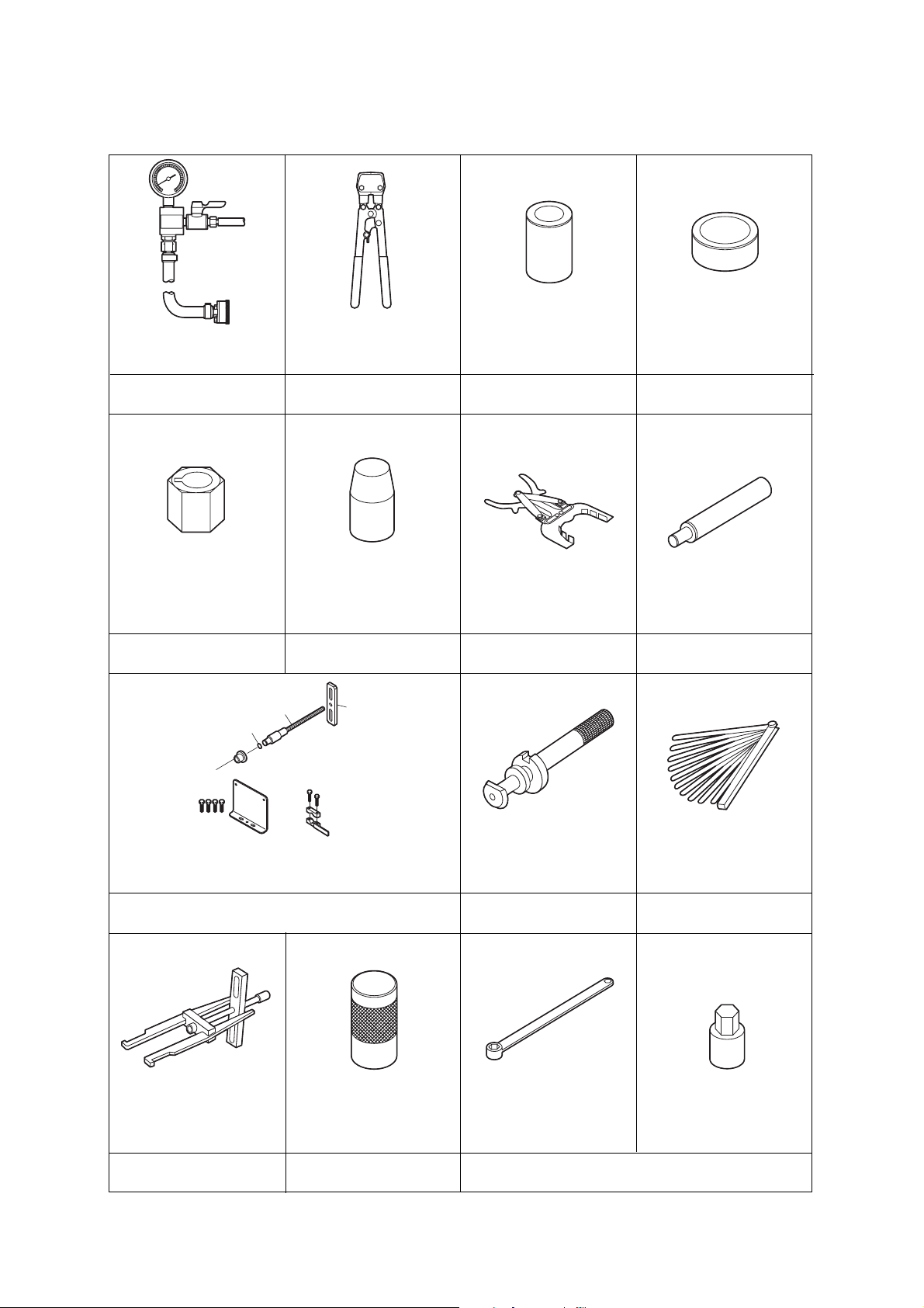
5. Special Tools
1. List of Special Tool
2-17
0.5
01.0
MPa
AIR
5.5MPa
3T5728800
FUEL
0.62MPa
3T5728680
3
T
5
7
2
8
7
1
0
3T5728150
3T5
728630
353-72245-1
332-60002-0
3A3-72713-0
345-72723-0
For removing and installing bevel gear B nut.
Pressure gauge assembly
3T5-72880-0
For measuring air rail fuel and
air pressure.
Crimping pliers
3T5-72864-0
For crimping OETIKER make
clamps.
Drive pulley press
3T5-72868-0
For press fitting in the drive
pulley.
Piston slider
3T5-72871-0
For installing the piston in the
air compressor.
Crankshaft holder
3T5-72815-0
O-ring setting tool (ø24)
3T5-72863-0
For installing O-rings on the
fuel injectors.
Piston ring wrench
353-72249-0
For installing and removing the
piston rings.
Piston pin tool
345-72215-0
For installing and removing
piston pins.
Backlash measuring tool
For measuring backlash between bevel gears A and B.
Thumbing gauge
3C8-72250-0
For measuring between bevel
gears A and B.
Filler gauge
353-72251-0
Bevel gear A bearing
puller assembly
345-72224-2
For removing bearing from
bevel gear A.
Bevel gear A bearing Setting tool
3C8-72719-0
For installing bevel gear
A bearing.
Bevel gear B nut wrench
346-72231-0
Bevel gear B nut socket
346-72232-0
For measuring clearances.
For removing and tightening
on the pulley nut.
 Loading...