

TOHATSU NB-1000, 2 Stroke Cylinder Series Service Manual
PNo. 003-21035-1
0509 NB 1000
Printrd in Japan
ドキュメント105.8.23 1:33PMページ1

TABLE OF CONTENTS
Service Safety
General Service Information
Fuel System
Powerhead
Midsection
1
2
3
4
5
Gearcase
Electrical System
6
7
1-/ 2-Cylinder
i

SECTION 1
SERVICE SAFETY
TABLE OF CONTENTS
Introduction·························································································································· 1-2
Safety Statements················································································································ 1-2
Safety Precautions ··············································································································· 1-3
Workmanship Standards······································································································ 1-5
Test Tank Guidlines ·············································································································· 1-7
1-/ 2-Cylinder
1-1
SECTION 1
Inadequate knowledge of safe shop practices can
result in severe injury or death. Review general
safety procedures and specific safety information
provided for each procedure prior to beginning
any repairs.
WARNING
INTRODUCTION
Marine manufacturers are required to comply with special regulations
and standards to ensure their products are safe and reliable for the
consumer. As the marine technician, it is your responsibility to keep
these products safe when performing normal rigging, repair and
maintenance operations.
It is not possible to foresee all safety hazards which may occur or
to include all the knowledge of an experienced technician in a
single service manual. Therefore, it is assumed that those using this
manual have a working knowledge of 2-cycle outboard engines and the
proper technical training for servicing them.
This section discusses safe shop practices and general safety
concerns relevant to the operations performed throughout this
manual. Read this section carefully and follow all safety statements in
this manual as they pertain to the procedures at hand. Remember,
always use common sense when servicing outboard engines!
SAFETY STATEMENTS
The following safety statements are found throughout this manual
and indicate information which, if ignored, could result in safety
hazards or faulty service techniques:
KC-5030
DANGER
Indicates the presence of a hazard which, if ignored,
WILL result in severe injury or death.
WARNING
Indicates the presence of a hazard which, if ignored,
COULD result in severe injury or death.
CAUTION
Indicates the presence of a hazard which, if ignored,
COULD result in minor personal injury or damage
to product, equipment, or other property.
NOTE
Indicates special information to facilitate the installation,
operation, or maintenance of the product or further
clarify information which is important but not hazard
related.
1-2
1-/ 2-Cylinder
SAFETY PRECAUTIONS
KC-4075.3
Handling Outboard Engines
• Never disable the neutral switch start-in-gear prevention system
to accommodate installation of a foot control or other option.
Always test the neutral switch and emergency stop switch before
returning an engine to the customer.
SERVICE SAFETY
• Lifting devices and hardware must be of suitable capacity for the
weight of the outboard engine. Some models are equipped with
a fixed hanger on the powerhead. Hanger may be used to lift the
complete engine or to remove the powerhead unit. Be aware the
engine may swing outward when lifted by the hanger.
• Engine stands must be in good condition, of adequate size, and
mounted properly to prevent unexpected shifting or collapse.
• Engine covers are guards to prevent personal contact with the
spinning flywheel and high voltage components such as spark
plugs and coils. Never wear jewelry or loose clothing near a
running engine. Keep hands, arms and hair away from the
flywheel. Never touch electrical components when the engine is
running.
•Two people working on a running engine must use extreme caution
and be aware of one another. Never attempt to start an engine or
operate any controls, including steering, before signaling your
partner.
•To prevent accidental startup during operations which may cause
the flywheel to turn, always perform the following steps:
1. Turn the ignition key to OFF and remove the key.
KC-5000
KC-4090
2. Disable the engine ignition system.
3. Shift engine to NEUTRAL and verify propeller shaft is not in
gear.
• Rotating propellers are not equipped with guards and can cause
severe injury or dismemberment. Always stay clear of rotating
propellers and make sure there is no possibility of engine startup
before removing or installing a propeller. The propeller nut must
always be tightened to torque specification prior to starting the
engine.
1-/ 2-Cylinder
1-3
SECTION 1
KC-5050
•Avoid running the engine at high RPM. Engine speed can easily
increase to excessive RPM when under a no load condition. To
avoid engine damage during testing, always use the correct test
propeller and keep engine speed below 2000 RPM.
• Run engines only in well ventilated areas to prevent exposure to
Carbon Monoxide (CO) gas. Direct and prolonged exposure to
CO wiII cause brain damage or death.
• Always wear eye protection, protective clothing, gloves and use
other applicable safety equipment when work activities present
the risk of personal injury.
Lead Acid Batteries
• Never check battery charge by placing a metal object across the
terminal posts; sparks may occur, resulting in serious burns.
•Avoid contact with battery acid. lf battery acid is spilled on skin,
thoroughly wash area with plenty of water. If battery acid gets
into eyes, flush eyes with water for at least 15 minutes and get
prompt medical attention.
• Never remove charger cables from a battery when the charger is
energized; sparks and explosion are possible. To remove charger
cables, follow these steps:
1. Turn the charger to OFF.
2. Disconnect the charger power cord from its power source.
3. Remove the charger cables from the battery posts.
• Batteries emit explosive vapor through the vented caps during
charging. Never charge or test batteries near sparks or flames;
explosion can result. Extinguish all smoking materials and flame
producing devices before charging and make sure the charging
area is weII ventilated.
KC-5032
KC-4080
• Make sure battery vents are not clogged or pressure may build
and cause battery to explode.
1-4
1-/ 2-Cylinder
Hazardous Materials
KC-5001
• Gasoline vapors are highly flammable and can cause an
explosion. Never smoke or allow sparks or flames nearby when
handling fuel Always store gasoline in a shaded, well ventilated
area in an approved safety container.
•Ventilate gasoline fumes as soon as detected. Be aware that
appliance pilot lights, such as those in furnaces and water
heaters, can ignite gasoline vapors and cause explosion.
• Never use gasoline as a cleaner, and always clean up fuel spills
immediately and properly dispose of rags in an approved safety
container.
• Read and follow the safety labels on products used around the
shop. Adhesives, lubricants, solvents, and fuel additives are
usually poisonous and flammable. Store and dispose of these
products properly.
Shop Environment
• Make sure the shop and your work area are properly ventilated.
SERVICE SAFETY
KC-5040
KC-0135
• Shops must be equipped with the proper tools and safety
equipment such as fire extinguisher, eye flushing device, and first
aid kit.
• Keep the shop clean and free of clutter. Clean up spills on the
floor as soon as possible to prevent someone from slipping.
WORKMANSHIP STANDARDS
1. Avoid damage to the mating surfaces of crankcase and cylinder
assembly. Do not use a sharp metal scraper to clean these areas.
2. Replace gaskets, O-rings, seals, cotter pins, lock nuts, and spring
pins when removed during repair operations.
3. Use only genuine factory replacement parts and accessories.
4. Use recommended special tools when specific repairs require
them.
5. Calibrate measurement tools and test equipment on a regular
basis.
6. Clean aIl metal parts with solvent before inspection and assembly
operations.
KC-5055
7. Use penetrating solvents when necessary to remove rusted or seized
hardware.
1-/ 2-Cylinder
1-5

SECTION 1
8. Keep all removed parts separated for ease of identification during
assembly.
9. Locate alignment marks on components being disassembled. If
marks are not present and should be, scribe or match mark them
yourself to ensure the pieces are assembled properly.
10. Follow torque sequences and specifications where they apply.
First, tighten each bolt in the specified sequence. Use the same
sequence to torque each bolt to final specification. Special torque
specifications are listed at the beginning of each section. Standard
torque specifications for common fasteners are listed in Section 3.
11. Use lubricant when assembling seals to prevent damage to the
seal lips. Make sure seal lips are facing the correct direction.
12. Use the correct type and amount of sealing compound on metal
to metal surfaces.
13. When using compressed air to clean or dry parts, make sure air
supply is regulated not to exceed 25 psi [172 kPa /1.76 kg/cm
2
].
14. Replace missing or damaged safety labels on the engine before
returning it to the customer.
1-6
1-/ 2-Cylinder
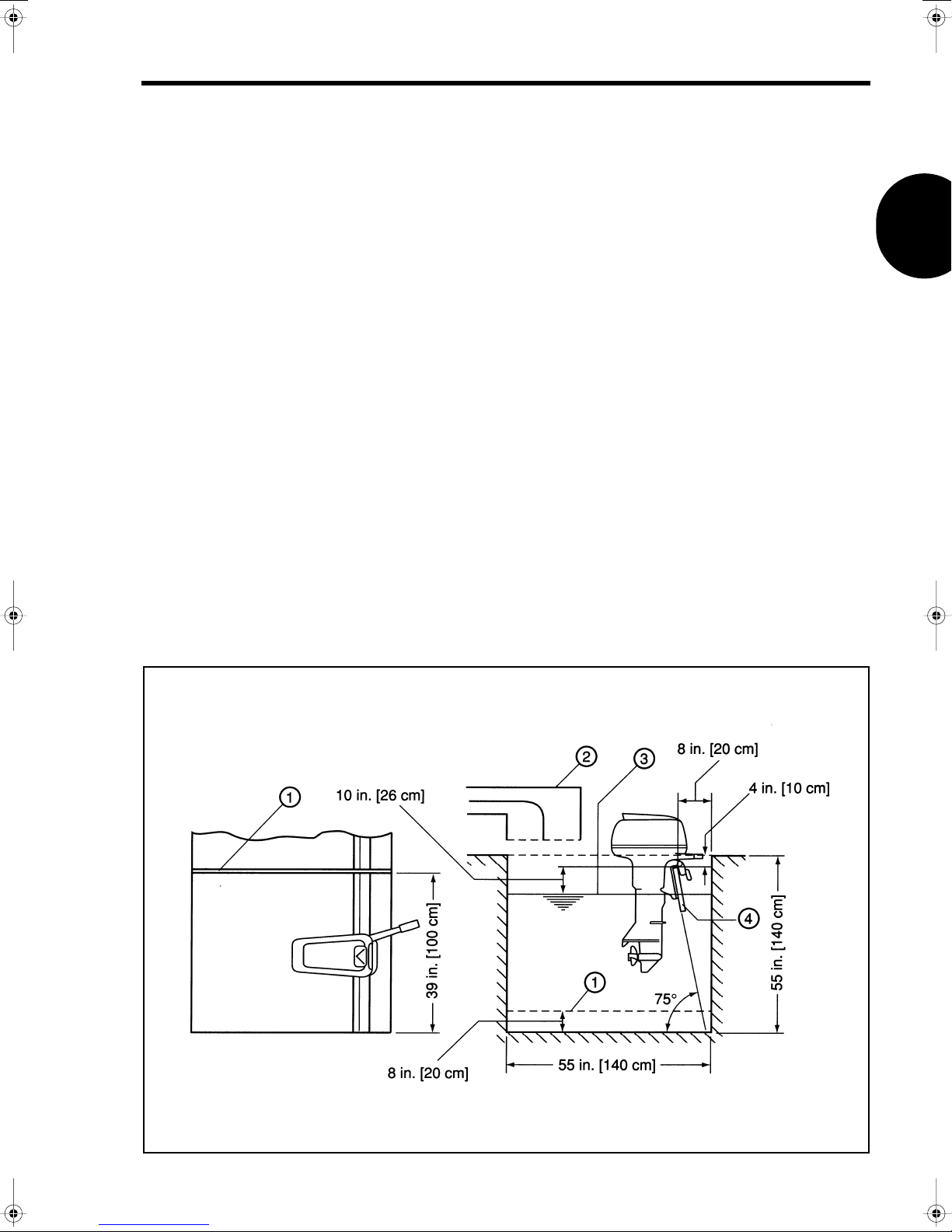
TEST TANK GUIDELINES
When properly setup, test tanks provide a safe and controlled environment
in which to perform outboard engine adjustment and testing procedures.
Test tanks must be setup to the minimum dimensions shown. If multiple
engines wiII be installed in the tank, secure partition plate
minimum dimensions are maintained for each outboard engine installed.
In addition, adhere to the following guidelines to prevent engine damage:
• Continuous usage raises the water temperature in the tankwhich
can lead to engine seizure. Make sure water temperature in the
tank does not exceed 77°F [25°C].
• Repeated use introduces carbon into the water which can adhere
to the engine cooling system and degrade its ability to cool the
engine. Always replace dirty tank water at regular intervals with
clean, fresh water.
• Exhaust gases produced during engine operation can collect
around the engine, causing suction into the carburetors and
affecting engine performance. To prevent this condition, install
forced ventilation equipment
engine and work area.
(2)
to remove gases away from the
(1)
so that the
SERVICE SAFETY
•Water may splash out of the tank during testing. Maintain water
leveI
(3)
in the tank as illustrated.
• Keep transom board
tank bottom to ensure near vertical engine position.
(4)
at an approximately 75° angle to the
1-/ 2-Cylinder
T1016
1-7

SECTION 2
GENERAL SERVICE
INFORMATION
TABLE OF CONTENTS
General Precautions············································································································· 2-2
Abbreviations and Symbols ································································································· 2-3
Unit Conversions·················································································································· 2-4
Service Specifications·········································································································· 2-5
Engine Specifications········································································································· 2-17
Lubrication Chart ··············································································································· 2-20
Periodic Inspections··········································································································· 2-24
Break-ln Procedure ············································································································ 2-27
Tune-Up Procedure ············································································································ 2-28
Emergency Stop Switch and Lanyard················································································ 2-29
Synchronization and Linkage Adjustments········································································ 2-30
Carburetor Adjustment······································································································· 2-36
Anodes - Inspection and Testing ······················································································· 2-38
1-/ 2-Cylinder
2-1

SECTION 2
GENERAL PRECAUTIONS
Before performing any service work on the outboard engine, read
and understand Section 1 - Service Safety.
Use only genuine factory replacement parts with equivalent
characteristics such as type, material, and strength. Failure to do
so may result in product malfunction and injury to the operator or
passengers.
Follow the
value for a certain fastener is not listed in the
Values
Rather than just repairing a bad part, use repair kits and overhaul
kits when applicable to ensure complete and efficient repair of the
complete component. Wear not readily noticed on other parts can
lead to malfunction soon after the repair.
When indicated in a procedure, use manufacturer special tools. ln
some cases, the use of substitute tools will damage the part.
When using compressed air to clean or dry parts, make sure air
supply is regulated not to exceed 25 psi [172 kPa / 1.76 kg/cm
Standard Torque Values
chart at the beginning of each section.
chart when a special torque
Special Torque
2
].
2-2
1-/ 2-Cylinder

GENERAL SERVICE INFORMATION
ABBREVIATIONS AND SYMBOLS
Abbreviations
A
AC
AH
approx.
API
ATDC
BTDC
°C
CCA
cm
3
cm
cm3/min
cu-in
DC
DVA
Kg-m
°F
fl oz
fl oz/min
ft
ft-lb
ft-Ibf/min
g
gal/hr
gal
GL
GM
HP
I.D.
in
in-lb
kg
2
kg/cm
ESG
kPa
kW
ampere
alternating current
ampere-hour
approximately
American Petroleum Institute
after top dead center
before top dead center
degree Celsius
cold cranking amp
centimeter
cubic centimeter
cubic centimeter per minute
cubic inch
direct current
direct volt adapter
kilogram meter
degree Fahrenheit
fluid ounce (U.S.)
fluid ounce (U.S.) per minute
foot
foot pound
foot pound force per minute
gram
gallon (U.S.) per hour
gallon (U.S.)
gear lubricant
General Motors Company
horsepower (U.S.)
inside diameter
inch
inch pound
kilogram
kilogram per square centimeter
electronic speed governor
kilopascal
kilowatt
L
L/hr
lb
mL
mm
mV
N
N·m
NMMA
No.
O.D.
oz
PS
psi
qt
RPM
SAE
sec.
t
TDC
V
VAC
VDC
W
Symbols
°
+
±
Ω
µ
%
liter
liter per hour
pound
milliliter
millimeter
millivolt
newton
newton meter
National Marine
Manufacturers Association
number
outside diameter
ounce
horsepower (metric)
pound per square inch
quart (U.S.)
revolution per minute
Society of Automotive Engineers
second
short ton 2000 lb
top dead center
volt
volt alternating current
volt direct current
watt
angular degree
plus
minus
plus or minus
ohm
micro
percent
1-/ 2-Cylinder
2-3

SECTION 2
UNIT CONVERSIONS
Unit Prefixes
Prefix Symbol Power
mega M x 1,000,000
kilo k x 1,000
centi c x 0.01
milli m x 0.001
micro µ x 0.000001
Units of Length
mile x 1.6090 = km
ft x 0.3050 = m
in x 2.5400 = cm
in x 25.4000 = mm
km x 0.6210 = mile
mx3.2810 = ft
cm x 0.3940 = in
mm x 0.0394 = in
Units of Volume
gal (U.S.) x 3.78540 = L
qt (U.S.) x 0.94635 = L
cu-in x 0.01 639 = L
cu-in x 16.38700 = mL
fl oz (U.S.) x 0.02957 = L
fl oz (U.S.) x 29.57000 = mL
3
cm
cm
3
x 1.00000 = mL
x 0.03382 = fl oz (U.S.)
Units of Torque
ft-lb x 1.3558 = N-m
ft-lb x 0.1383 = kg-m
in-Ib x 0.1130 = N-m
in-lb x 0.0115 = kg-m
kg-m x 7.2330 = ft-lb
kg-m x 86.8000 = in-lb
kg-m x 9.8070 = N-m
N-m x 0.7376 = ft-lb
N-m x 8.8510 = in-lb
N-m x 0.1020 = kg-m
Units of Pressure
psi x 0.0689 = bar
psi x 6.8950 = kPa
psi x 0.0703 = kg/cm
bar x 14.5030 = psi
bar x 100.0000 = kPa
bar x 29.5300 = in Hg (60°F)
kPa x 0.1450 = psi
kPa x 0.0100 = bar
kPa x 0.0102 = kg/cm
2
kg/cm
2
kg/cm
2
kg/cm
in Hg (60°F) x 0.0333 = bar
in Hg (60°F) x 3.3770 = kPa
in Hg (60°F) x 0.0344 = kg/cm
x 14.2200 = psi
x 0.9807 = bar
x 98.0700 = kPa
2
2
2
Units of Mass
lb x 0.45360 = kg
oz x 28.35000 = g
kg x 2.20500 = lb
gx0.03527 = oz
Units of Force
lbf x 4.4480 = N
lbf x 0.4536 = kgf
Nx0.2248 = lbf
Nx0.1020 = kgf
kgf x 2.2050 = lbf
kgf x 9.8070 = N
Units of Power
HP x 1.01400 = PS
HP x 745.70000 = W
HP x 550.00000 = ft-lbf/s
PS x 0.98630 = HP
PS x 735.50000 = W
PS x 542.50000 = ft-lbf/s
Wx0.00134 = HP
Wx0.00136 = PS
Wx0.73760 = ft-lbf/s
kW x 1.34100 = HP
kW x 1.36000 = PS
kW x 737.56000 = ft-lbf/s
ft-lbf/s x 0.00181 = HP
ft-Ibf/s x 0.00184 = PS
ft-lbf/s x 1.35600 = W
Units of Temperature
°F = (1.8 • °C) + 32
°C = 0.556 • (°F - 32)
2-4
1-/ 2-Cylinder

GENERAL SERVICE INFORMATION
SERVICE SPECIFICATIONS
Standard Torque Values
To rque
Size
M4 10 - 17 0.8 - 1.4 1 - 2 0.1 - 0.2
M5 26 - 35 2.2 - 2.9 3 - 4 0.3 - 0.4
M6 44 - 52 3.6 - 4.3 5 - 6 0.5 - 0.6
M8 97 - 133 8 - 11 11 - 15 1.1 - 1.5
M10 204 - 274 17 - 22 23 - 31 2.3 - 3.1
These torque values apply only when a special torque specification is not listed in the
Values
chart at the beginning of each section.
in-lb ft-lb N-m kg-m
Special Torque
1-/ 2-Cylinder
2-5
SECTION 2
2
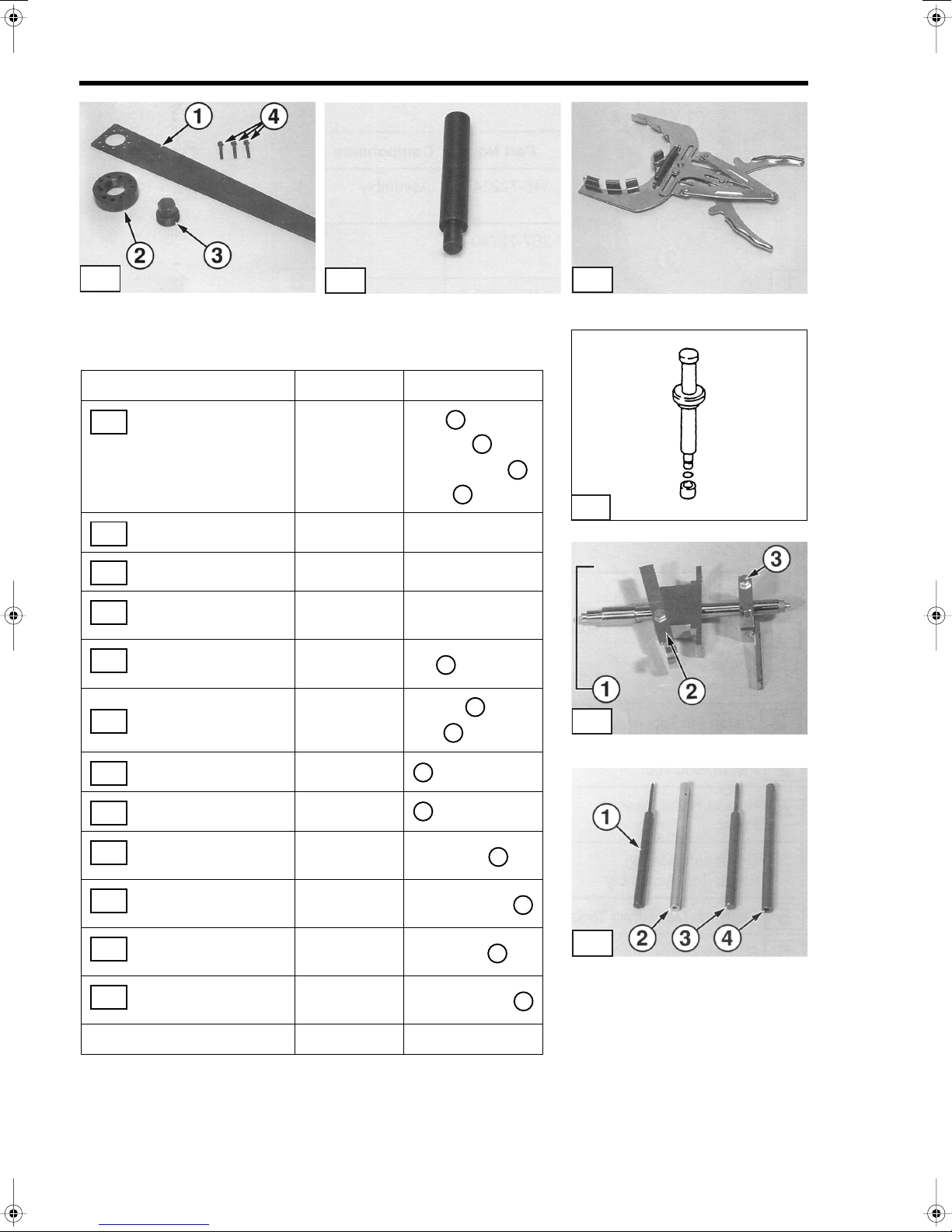
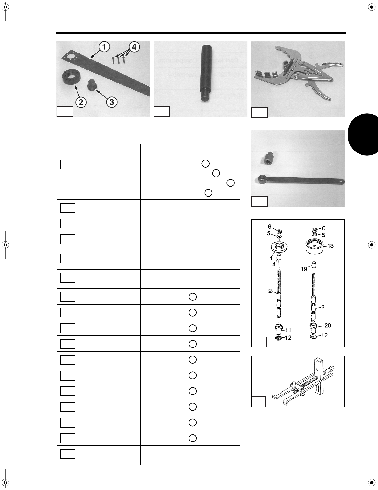
Manufacturer Special Tools Required - 1-2 Cylinder
2.5
/
3.5
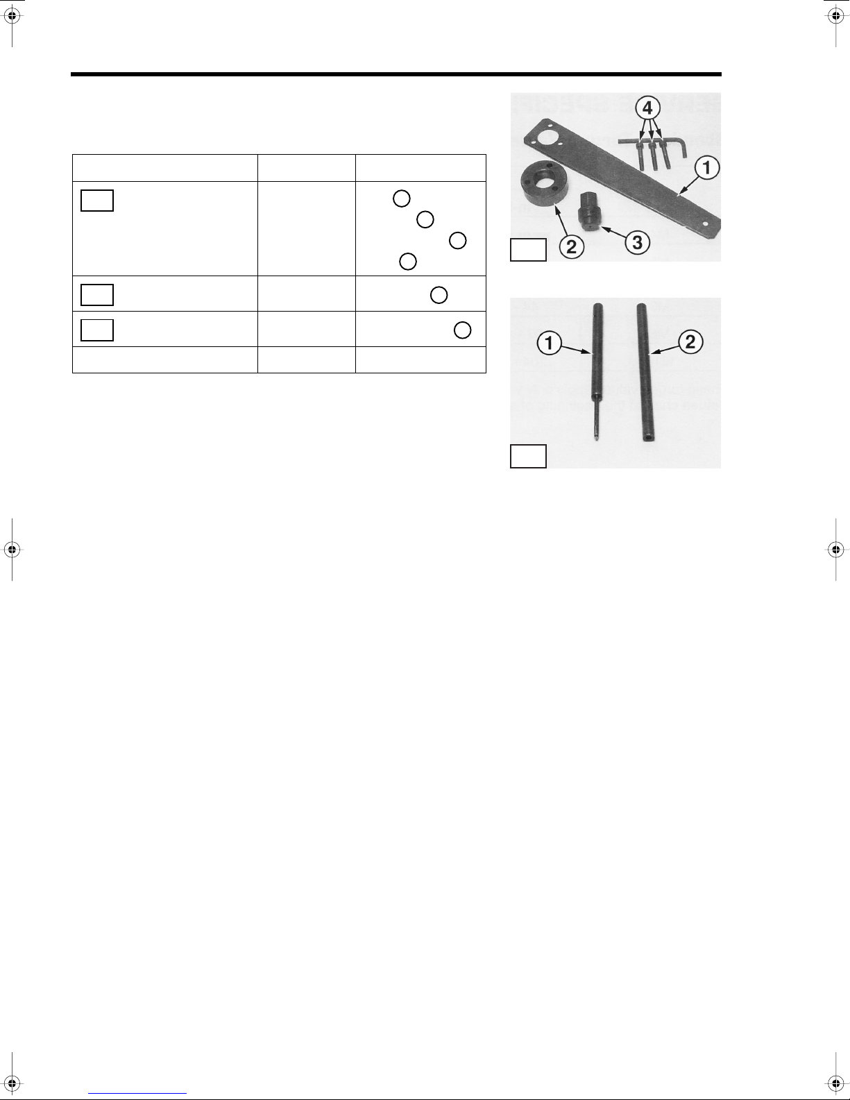
Tool Description Part No. Components
Flywheel Puller
1
Assembly
Spring Pin Tool
2
Spring Pin Tool
2
Tool Box 353-72254-0
✳
: For 3.5B
✳
✳
309-72214-0
or
3V1-72211-0
345-72227-0
345-72228-0
Arm
1
Adapter
Pressing Bolt
Bolts
Pin Punch
HoIIow Punch
2
3
4
1
1
2
T1900
T1902
2-6
1-/ 2-Cylinder
GENERAL SERVICE INFORMATION
1
4
1
3
T1908
5
1
5
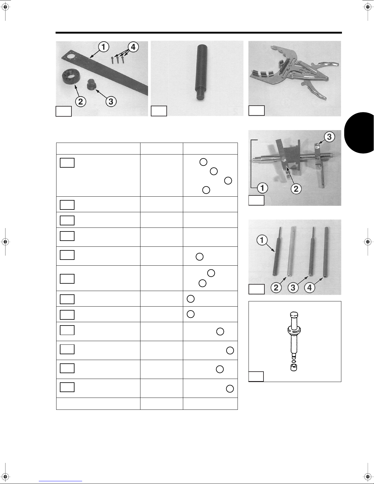
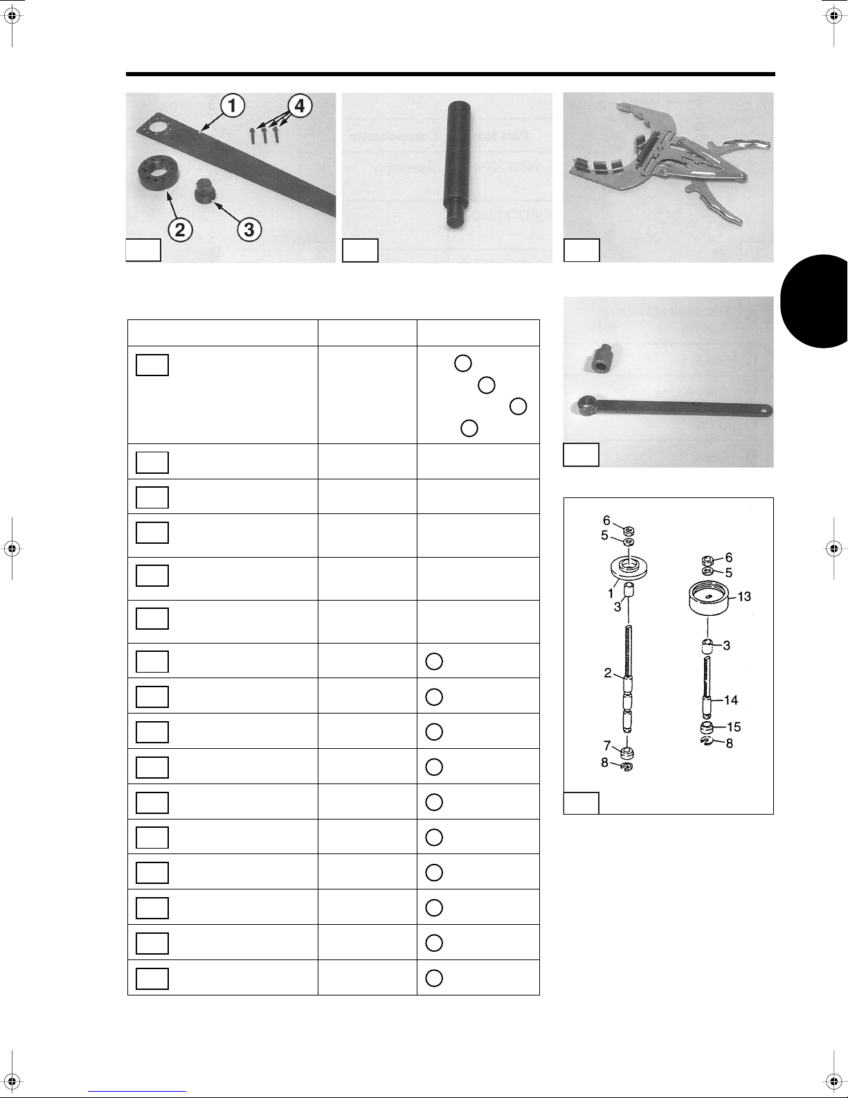
Tool Description Part No. Components
Flywheel Puller
1
Assembly
Piston Pin Tool
2
Piston Ring Tool
3
Driveshaft Needle
6
Bearing Tool Assembly
Backlash Measuring
4
Tool
Sub Assembly
4
T1904
369-72211-0
332-72215-0
353-72249-0
369-72900-0
369-72740-0
369-72730-0
2
Arm
Adapter
Pressing Bolt
Bolts
Kit
Except
and
2
1
2
3
T1901
3
3
4
T1906
T1907
Arm
4
Clamp Assembly
4
Spring Pin Tool
5
(3 mm Dia.)
Spring Pin Tool
5
(3 mm Dia.)
Spring Pin Tool
5
(3.5 mm Dia.)
Spring Pin Tool
5
(3.5 mm Dia.)
Tool Box 353-72254-0
1-/ 2-Cylinder
369-72727-0
3B7-72720-0
345-72227-0
345-72228-0
369-72217-0
369-72218-0
2
3
Pin Punch
HoIIow Punch
Pin Punch
HoIIow Punch
2
6
4
2-7
SECTION 2
4
1
2
3
T1907
5
1
T1904
8/9.8
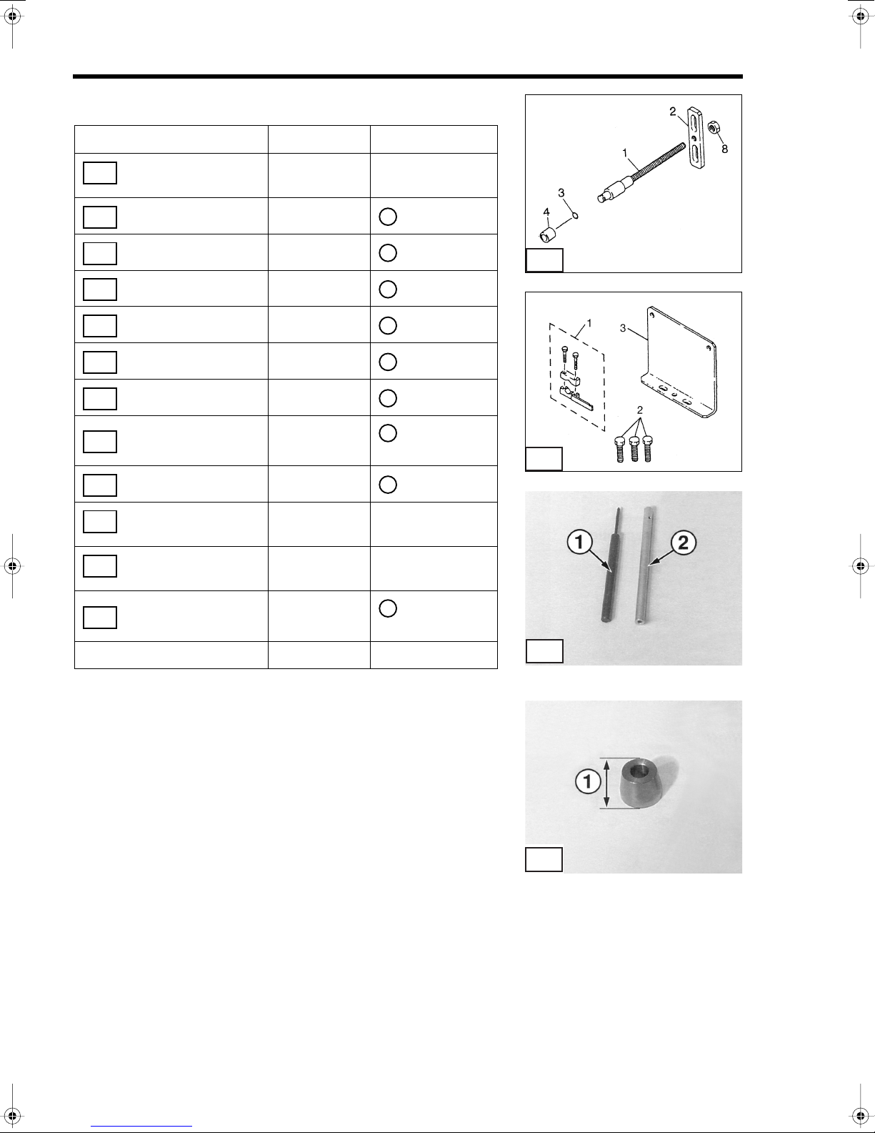
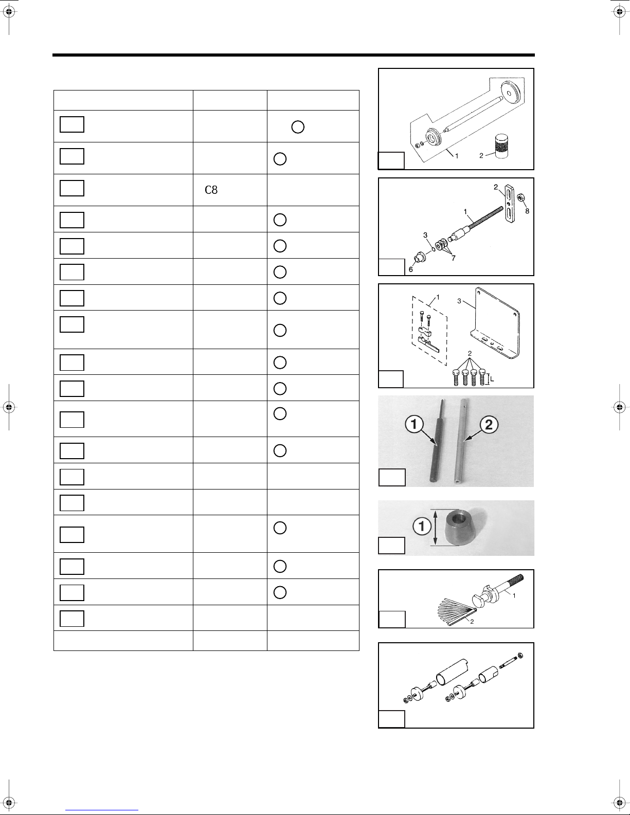
Tool Description Part No. Components
Flywheel Puller
1
Assembly
Piston Pin Tool
2
Piston Ring Tool
3
Driveshaft Needle
Bearing Tool Assembly
Backlash Measuring
5
Tools
Sub Assembly
5
2
369-72211-0
332-72215-0
353-72249-0
3B2-72900-0
369-72740-0
369-72730-0
Arm
Adapter
pressing Bolt
Bolts
Kit
Except
and
3
T1910
1
2
3
4
T1906
4
1
2
3
Arm
5
clamp Assembly
5
spring Pin Tool
6
(3 mm Dia.)
spring Pin Tool
6
(3 mm Dia.)
spring Pin Tool
6
(3.5 mm Dia.)
spring Pin Tool
6
(3.5 mm Dia.)
Tool Box 353-72254-0
2-8
3B2-72727-0
3B7-72720-0
345-72227-0
345-72228-0
369-72217-0
369-72218-0
2
3
Pin Punch
HoIIow Punch
Pin Punch
HoIIow Punch
6
4
T1908
1-/ 2-Cylinder
GENERAL SERVICE INFORMATION
1
2
3
5 56 57 58 513
14
15
5
1
9.9/15/18
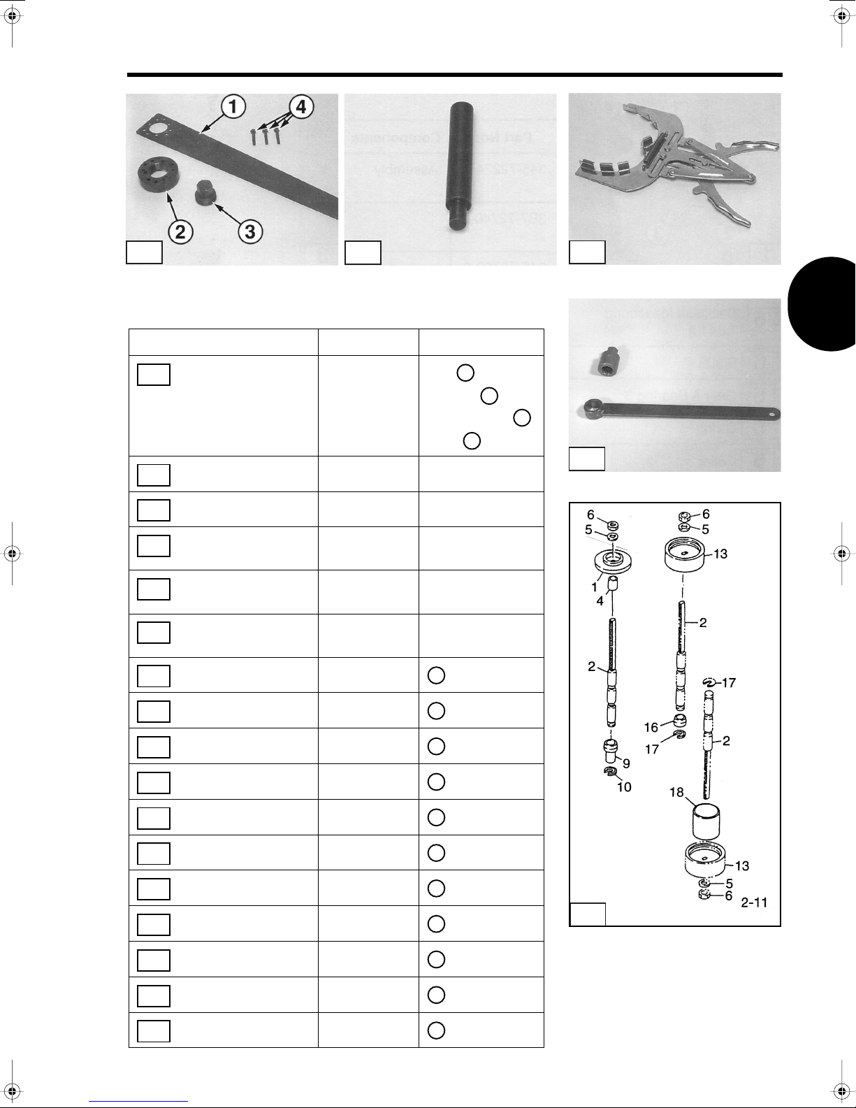
Tool Description Part No. Components
Flywheel Puller
1
Assembly
Piston Pin Tool
2
Piston Ring Tool
3
Wrench, Bevel Gear B
4
Nut
Socket, Bevel Gear B
4
Nut
Needle Roller Bearing
5
Puller
T1904
2
369-72211-0
332-72215-0
353-72249-0
346-72231-0
350-72232-0
3C8-72700-0 Kit
Arm
1
Adapter
pressing Bolt
Bolts
2
4
T1910
3
3
4
T1906
T1918
Flange A
5
Shaft
5
Shaft Stopper A
5
Washer
5
Nut, 12P=1.25
Guide A
Retainer A
Flange B
Shaft B
5
Guide B
5
3C8-72701-0
346-72702-0
350-72704-0
346-72707-0
346-72706-0
350-72705-0
350-72703-0
346-72701-5
350-72702-5
350-72705-5
1-/ 2-Cylinder
2-9
SECTION 2
8
T1800
8
9.9/15/18 Continued
Tool Description Part No. Components
Backlash Measuring
6
Tool Kit
Shaft
6
Plate
6
O-ring
6
Collar
6
Nut, M10
6
Clamp Assembly
7
Bolt, H625
7
Plate, Dial Gauge
7
Spring Pin Tool
8
(3 mm Dia.)
Spring Pin Tool
(3 mm Dia.)
3C8-72234-0 Kit
345-72723-0
3A3-72724-0
332-60002-0
350-72245-0
930191-1000
3B7-72720-0
910191-0625
3B7-72729-0
345-72227-0 Pin Punch
345-72228-0 Hollow Punch
1
2
3
4
, 2 nuts
8
1
for lower
2
pump case
3
6
7
Clutch Pin Snap Tool
9
Tool Box 353-72254-0
350-72229-0
= 1.85 in
1
47 mm
9
T1799
2-10
1-/ 2-Cylinder
GENERAL SERVICE INFORMATION
4
5
1
T1904
25/30
Tool Description Part No. Components
Flywheel Puller
1
Assembly
Piston Pin Tool
2
Piston Ring Tool
3
Wrench, Bevel Gear
B Nut
Socket, Bevel Gear B
4
Nut
Needle Roller
5
Bearing Puller
2
369-72211-0
345-72215-0
353-72249-0
346-72231-0 Wrench
346-72232-0 Socket
3C8-72700-0 Kit
Arm
Adapter
Pressing Bolt
Bolts
3
T1910
1
2
3
4
4
T1906
T1918
Flange A
5
Shaft
5
Shaft Stopper
5
Washer
5
Nut, 12P=1.25
5
Guide A
5
Retainer A
5
Flange B
5
Guide B
5
Retainer B
5
Spacer
5
3C8-72701-0
346-72702-0
346-72704-0
346-72707-0
346-72706-0
346-72705-0
346-72703-0
346-72701-5
346-72705-5
346-72703-5
346-72708-0
1
2
4
5
6
9
10
13
16
17
18
1-/ 2-Cylinder
2-11

SECTION 2
9
25/30 Continued
Tool Description Part No. Components
Bevel Gear
6
Bearing Puller
Bearing Outer
7
Press Kit
Bevel Gear Bering
7
Installing Tool
Backlash Measuring
8
TooI Kit
Shaft
8
Plate
8
O-ring
8
ColLar
8
Cone Disk
8
Spring, d=12
Nut, M10
8
3A3-72755-0 Assembly
3B7-72739-0
346-72719-0
3C8-72234-0 Kit
345-72723-0
3A3-72724-0
332-60002-0
346-72245-1
3B7-72734-0
930191-1000
Kit,
1
, Ø 32 mm
2
1
2
3
5
, 2pcs
7
6
7
8
Clamp Assembly
9
Bolt, H625
9
Dial Gauge Plate
9
Spring Pin Tool A
10
(3 mm Dia.)
Spring Pin Tool B
10
(3 mm Dia.)
Clutch Pin Snap Tool
11
Shimming Gauge
12
Thinkness Gauge
12
Rubber Mount Puller
13
Tool Box 353-72254-0
3B7-72720-0
910191-0625
3B7-72729-0
345-72227-0 Pin Punch
345-72228-0 HoIIow Punch
346-72229-0
346-72250-0
353-72251-0
361-72760-0 Kit
1
for lower
2
pump case
3
= 1.97 in
1
50 mm
1
2
10
11
12
T1800
T1799
2-12
13
T1929
1-/ 2-Cylinder
GENERAL SERVICE INFORMATION
4
5
1
T1904
40
Tool Description Part No. Components
Flywheel Puller
1
Assembly
Piston Pin Tool
2
Piston Ring Tool
3
Wrench, Bevel Gear
B Nut
Socket, Bevel Gear
4
B Nut
Needle Roller
5
Bearing Puller
2
Arm
369-72211-0
345-72215-0
353-72249-0
346-72231-0 Wrench
345-72232-0 Socket
3C8-72700-0 Kit
Adapter
Pressing Bolt
Bolts
T1910
1
2
3
4
3
T1906
4
T1918
Flange A
5
Shaft
5
Shaft Stopper A
5
Washer
5
Nut, 12P=1.25
5
Guide A
5
Retainer A
5
Flange B
5
Shaft Stopper B
5
Guide
5
Bevel Gear
6
Bearing Puller
3C8-72701-0
346-72702-0
346-72704-0
346-72707-0
346-72706-0
345-72705-0
345-72703-0
346-72701-5
345-72704-5
345-72705-5
3A3-72755-0 Assembly
1
2
4
5
6
11
12
13
19
20
6
1-/ 2-Cylinder
2-13
SECTION 2
2
10
T1800
40 Continued
Tool Description Part No. Components
Bearing Outer
7
Press Kit
Bevel Gear Bering
7
Installing Tool
Backlash Measuring
8
Tool
Shaft
8
Plate
8
O-ring
8
Collar
8
Cone Disk
8
Spring, d=12
Nut, M10
8
Clamp Assembly
9
Bolt, H625
9
3B7-72739-0
3C8-72719-0
3
-72234-0
345-72723-0
3A3-72724-0
332-60002-0
353-72245-1
345-72763-0
930191-1000
3B7-72720-0
910191-0625
1
Kit,
, Ø 42 mm
2
Kit
1
2
3
6
, 3 pcs
7
8
1
for lower
pump case
7
8
9
Plate, Dial Gauge
9
Spring Pin Tool A
10
Spring Pin Tool B
10
Clutch Pin Snap Tool
11
Shimming Gauge
12
Thickness Gauge
12
Rubber Mount Puller
13
Tool Box 353-72254-0
3B7-72729-0
345-72227-0 Pin Punch
345-72228-0 Hollow Punch
345-72229-0
3C8-72250-0
353-72251-0
361 -72760-0 Kit
3
= 2.36 in
1
60 mm
1
2
11
12
13
T1799
2-14
1-/ 2-Cylinder

GENERAL SERVICE INFORMATION
General Equipment Required
Water Pressure Gauge, 0 - 15 psi [0 - 103 kPa / 0 - 1 kg / cm2]
Fuel Pressure Gauge, 0 - 15 psi [0 - 103 kPa / 0 - 1 kg / cm
To rque Wrench, 0 - 150 in-lb [0 - 17 N·m / 0- 1.7kg-m]
To rque Wrench, 0 - 750 ft-lb [0 - 1000 N·m / 0 - 100 kg-m]
Dial Gauge, minimum scale 0.0001 in [0.01 mm]
Micrometer Set or Dial Caliper, minimum scale 0.0001 in [0.01 mm]
Telescoping Gauge, Inside Micrometer Set, or Dial Caliper, minimum scale 0.0001 in [0.01 mm]
Variable Load High Rate Discharge Tester,
Analog Multimeter,
Digital Multimeter,
Electronic Specialties® Model M-530 or equivalent
Electronic Specialties® Model KD 3200 or equivalent
Digital Pulse Tachometer, 10 - 6000 RPM,
Electronic Specialties® Model 700 or equivalent
Electronic Specialties® Model 321 or equivalent
Ammeter, 0 - 100 A
Gearcase Pressure Tester,
Gearcase Vacuum Tester,
Stevens® S-34 or equivalent
Stevens® V-34 or equivalent
Engine Compression Gauge, 0 - 300 psi [0 - 2000 kPa / 0 - 20 kg/cm2]
Spark Gap Tester,
Stevens® S-13C, S-48, or equivalent
Flexible Fuel Tubing, 1/4 in I.D. x 5 in [6 mm I.D. x 127 mm]
Flexible Fuel Tubing, 3/8 in I.D. x 5 in [9.5 mm I.D. x 127 mm]
Industrial Thermometer, minimum 300°F [150°C]
®
Heat-Resistant Container,
Pyrex
Bearing Puller
Seal Pullers
Seal Installers
Heat Gun
Hydrometer
2
]
1-/ 2-Cylinder
2-15

SECTION 2
Consumables Required
Threadlocker,
Threadlocker,
Gasket Dressing,
Gasket Sealant,
Anaerobic Gasket Maker,
Silicone Sealant,
Super Bond Adhesive,
Cleaning Pads,
Low Temperature Lithium Grease
Genuine Grease or Equivalent Friction Surface Marine Grease
Power Trim/Tilt Fluid,
IsopropyI Alcohol
Cleaning Solvent
Gasket Remover
Gear Lubricant,
Engine Lubricant,
Automotive Crankcase Oil, flashpoint above 300°F [150°C]
Battery Spray Protector,
Electrical Shrink Tubing, various diameters
Loctite® 242
Loctite® 243
Permatex® Hylomar® Aerosol High-Temp Gasket Dressing
Permatex® High Tack Gasket Sealant
Loctite® 518
Permatex® Hi-Temp RTV Silicone Gasket
Permatex® Super Glue Gel
Scotch-Brite® Abrasive Pads
Nisseki® power torque fluid or GM approved automatic transmission fluid
Genuine gear oil or APl grade GL5, SAE #80 - #90
Genuine engine oil or NMMA certified TC-W3 oil
Permatex® Battery Protector & Sealer
2-16
1-/ 2-Cylinder

GENERAL SERVICE INFORMATION
ENGINE SPECIFICATI0NS
Operation
Power
2.5 .................................................. 2.5 HP [1.8 kW]
3.5 .................................................. 3.5 HP [2.6 kW]
5 ........................................................ 5 HP [3.7 kW]
8 ........................................................ 8 HP [5.9 kW]
9.8 .................................................. 9.8 HP [7.2 kW]
9.9 .................................................. 9.9 HP [7.3 kW]
15 .................................................. 15 HP [11.0 kW]
18 .................................................. 18 HP [13.2 kW]
25 .................................................. 25 HP [18.4 kW]
30 .................................................. 30 HP [22.1 kW]
40 .................................................. 40 HP [29.4 kW]
Full Throttle RPM Range
2.5 ........................................................3800 - 5200
3.5A
/ 3.5B2.........................................4200 - 5300
2
5 ...........................................................4500 - 5500
8 ...........................................................4500 - 5500
9.8 ........................................................5000 - 6000
9.9 ........................................................4500 - 5300
15, 18 ...................................................5200 - 5800
25 .........................................................5000 - 6000
30 .........................................................5150 - 5850
40 .........................................................5200 - 5800
lN
Idle RPM GEAR NEUTRAL
2.5, 3.5A2...............................1100 —
3.5B
......................................1100 1300
2
5 .............................................. 850 1000
8, 9.8 ....................................... 750 950
9.9, 15, 18 ............................... 800 950
25, 30 ...................................... 900 1050
40 ............................................ 850 1000
Fuel Consumption at Full Throttle
2.5 ............................................. 0.37 g/hr [1.4 L/hr]
3.5 ............................................. 0.45 g/hr [1.7 L/hr]
5 ................................................ 0.66 g/hr [2.5 L/hr]
8 .................................................. 1.0 g/hr [4.3 L/hr]
9.8 ............................................. 1.35 g/hr [5.1 L/hr]
9.9 ............................................. 1.45 g/hr [5.5 L/hr]
15 .............................................. 1.93 g/hr [7.3 L/hr]
18 .............................................. 2.25 g/hr [8.5 L/hr]
25 ............................................ 3.30 g/hr [12.5 L/hr]
30 ............................................... 3.96 g/hr [15 L/hr]
40 ............................................... 4.49 g/hr [17 L/hr]
Test Propeller
2.5, 3.5A2............................................ 309-64111-0
................................................... 3F0-64111-0
3.5B
2
5 ......................................................... 369-64111-0
8, 9.8 .................................................. 3B2-64111-0
9.9, 15, 18 .......................................... 362-64111-0
25, 30 ................................................. 364-64111-5
40 ....................................................... 348-64111-0
Powerhead
Number of Cylinders
2.5, 3.5, 5 .............................................................. 1
8, 9.8, 9.9, 15, 18, 25, 30, 40 ................................ 2
Displacement
2.5, 3.5 .....................................4.6 cu. in [74.6 cm3]
5 ..............................................6.22 cu. in [102 cm
8, 9.8 .......................................10.3 cu. in [169 cm
9.9, 15 ...................................15.07 cu. in [247 cm
18 ..........................................17.94 cu. in [294 cm
25, 30 ....................................26.18 cu. in [429 cm
40 ..........................................30.08 cu. in [493 cm
Standard Bore
2.5, 3.5 ........................................... 1.85 in [47 mm]
5 ..................................................... 2.17 in [55 mm]
8, 9.8 .............................................. 1.97 in [50 mm]
9.9, 15 ............................................ 2.17 in [55 mm]
18 ................................................... 2.36 in [60 mm]
25, 30 ............................................. 2.68 in [68 mm]
40 ................................................... 2.76 in [70 mm]
Stroke
2.5, 3.5 ........................................... 1.69 in [43 mm]
5, 8, 9.8 .......................................... 1.69 in [43 mm]
9.9, 15, 18 ...................................... 2.05 in [52 mm]
25, 30 ........................................... 2.323 in [59 mm]
40 ................................................. 2.520 in [64 mm]
Piston Clearance
2.5, 3.5 ............0.0024 - 0.0035 in [0.06 - 0.09 mm]
5 ..........................0.008 - 0.020 in [0.02 - 0.05 mm]
8, 9.8 ...................0.008 - 0.020 in [0.02 - 0.05 mm]
9.9, 15, 18 .......0.0020 - 0.0035 in [0.05 - 0.09 mm]
25, 30 ..............0.0024 - 0.0039 in [0.06 - 0.10 mm]
40 ....................0.0020 - 0.0039 in [0.05 - 0.10 mm]
Piston Ring End Gap
2.5, 3.5, 5, 8, 9.8 ............................ 0.007 - 0.013 in
[0.18 - 0.33 mm]
9.9, 15, 18 ...........0.008 - 0.019 in [0.20 - 0.40 mm]
25, 30 ..................0.013 - 0.019 in [0.33 - 0.48 mm]
40 ........................0.008 - 0.016 in [0.20 - 0.40 mm]
3
]
3
]
3
]
3
]
3
]
3
]
1-/ 2-Cylinder
2-17
SECTION 2
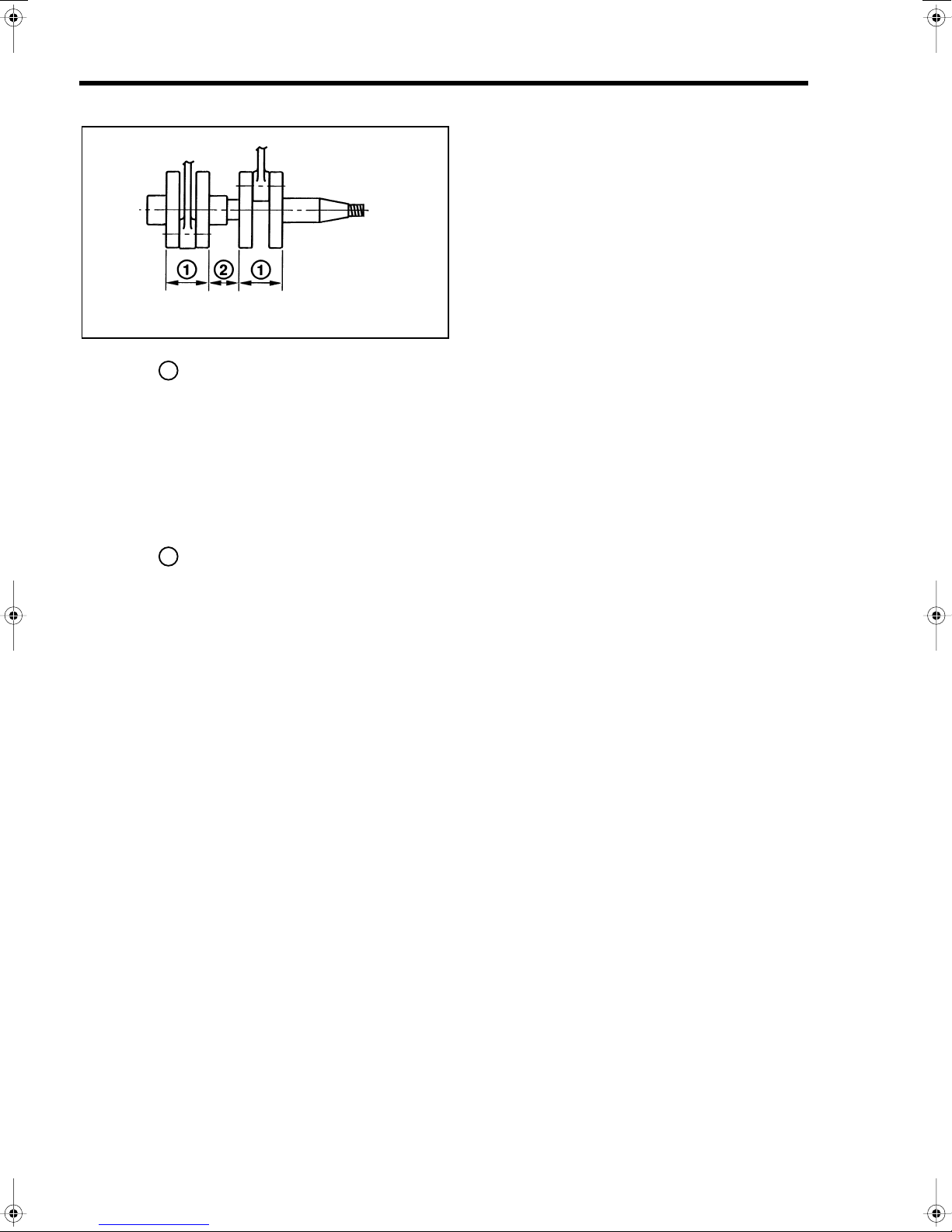
Crankshaft Dimensions
T1044
Dimension
2.5, 3.5 ..................1.417 ± 0.002 in [36 ± 0.05 mm]
5.............................1.575 ± 0.002 in [40 ± 0.05 mm]
8, 9.8......................1.654 ± 0.002 in [42 ± 0.05 mm]
9.9, 15, 18................1.890 ± 0.004 in [48 ± 0.1 mm]
25, 30......................2.047 + 0 in [52 + 0 mm]
40..........................2.071 + 0 in [52.6 + 0 mm]
Dimension
2.5, 3.5...................................................................N/A
5.............................................................................N/A
8, 9.8.........................0.984 ± 0.002 in [25 ± 0.05 mm]
9.9, 15, 18.................1.299 ± 0.002 in [33 ± 0.05 mm]
25, 30........................1.496 ± 0.002 in [38 ± 0.05 mm]
40...........................1.591 ± 0.002 in [40.4 ± 0.05 mm]
1
-
0.001 - 0.02
-
0.002 - 0.05
2
Gearcase
Gear Ratio
2.5, 3.5.............................................................. 13 : 24
5........................................................................ 13 : 28
8, 9.8................................................................. 13 : 27
9.9, 15, 18......................................................... 13 : 24
25, 30................................................................ 12 : 23
40...................................................................... 13 : 25
Lubricant
Capacity
2.5A, 3.5A .....................Approx. 3.0 U.S. fl oz [90 mL]
3.5B ............................Approx. 6.1 U.S. fl oz [180 mL]
5..................................Approx. 6.6 U.S. fl oz [195 mL]
8, 9.8.........................Approx. 10.8 U.S. fl oz [320 mL]
9.9, 15, 18.................Approx. 12.5 U.S. fl oz [370 mL]
25, 30..........................Approx. 9.5 U.S. fl oz [280 mL]
40..............................Approx. 14.2 U.S. fl oz [420 mL]
................................ Genuine manufacturer
gear oil or API GL5, SAE #80 - #90
Clutch System
2.5, 3.5A........................ None (Forward gear only)
3.5B.............................................. Dog clutch type
(Forward gear and Neutral only)
5, 8, 9.8, 9.9, 15, 18, 25, 30, 40 ........... Dog clutch
type (Forward-Neutral-Reverse)
Electrical System
Ignition Type............. Flywheel magneto capacitor
discharge
Ignition Timing
See Ignition Timing Adjustment in Section 2
Spark Plug (with resistor)
2.5, 3.5 .................................. NGK BPR6HS-10 or
Champion RL87YC10
5, 8, 9.8 .................................. NGK BPR7HS-10or
Champion RL82YC10
9.9, 15, 18, 25, 30, 40 ............. NGK BR7HS-10 or
Champion RL82C10
Spark Plug Gap
AII Models .............0.035 - 0.039 in [0.9 - 1.0 mm]
Battery
2.5, 3.5 .......................................................... None
5 .........................None (Optional - 12V 30 - 35 AH
recommended)
8, 9.8 .........................None (Optional - 12V 40 AH
recommended)
9.9, 15, 18 .................None (Optional - 12V 40 AH
recommended)
25, 30 ........................None (Optional - 12V 40 AH
recommended)
40 ..............................None (Optional - 12V 70 AH
recommended)
Engine Fuse
2.5, 3.5 .......................................................... None
5 ................................None (With Optional Battery
Charger - 10A)
8, 9.8 .........................None (With Optional Battery
Charger or Starter - 15A)
9.9, 15, 18 .................None (With Optional Battery
Charger or Starter - 15A)
25, 30, 40 ..................None (With Optional Battery
Charger or Starter - 15A)
2-18
1-/ 2-Cylinder

GENERAL SERVICE INFORMATION
Alternator
2.5, 3.5 ............................................................None
5 ................................... None (Optional - 12V 60W)
8, 9.8 ............................ None (Optional - 12V 80W)
9.9, 15, 18, 25, 30, 40 ...............................12V 80W
Charging Performance (at 1500 RPM)
N/A
Charging Performance (at 5500 RPM)
5 (Optional).........................................................4 A
8, 9.8, 9.9, 15, 18, 25, 30, 40 .............................5 A
Number of Tachometer-to-Alternator
Coil Impulses
2.5, 3.5 .............................................................. N/A
5 ............................................................................ 2
8, 9.8, 9.9, 15, 18, 25, 30, 40 ................................ 4
Alternator Coil Resistance
2.5, 3.5 .............................................................. N/A
5 ......................................................... 0.31 - 0.47
8, 9.8 .................................................. 0.24 - 0.36
9.9, 15, 18, 25, 30 .................... Y-W : 0.65 - 0.98
Y-B : 0.31 - 0.47
W-B : 0.37 - 0.55
40 ............................................. Y-W : 0.65 - 0.98
Y-B : 0.31 - 0.47
W-B : 0.37 - 0.55
Fuel and Lubricant System
Required Fuel, Lubricant, and Mix Ratio
See Fuel System Requirements in Section 3
NOTE
A special mix ratio is required during
break-in. See “Break-ln” at end of
this section.
Carburetor
2.5, 3.5 ...........................................SIide valve type
carburetor, float feed
5, 8, 9.8, 9.9, 15,
18, 25, 30, 40 ........................... Butterfly valve type
Ω
Ω
Ω
Ω
Ω
Ω
Ω
Ω
carburetor, float feed
lgnition Coil Resistance (±25%)
Primary Coil
2.5, 3.5 ............................................... 0.18 - 0.24
5 ........................................................... 0.2 - 0.38
9.9, 15, 18, 25, 30, 40 ............................ 0.2 - 0.3
Secondary Coil
2.5, 3.5 ................................................ 2.7 - 3.7
5 .......................................................... 3.0 - 4.4 KΩ
8, 9.8 ............................................... 1.95 - 3.25 KΩ
9.9, 15, 18 ........................................... 4.1 - 6.1 KΩ
25, 30, 40 ............................................ 4.1 - 6.1 KΩ
K
Ω
Ω
Ω
Ω
1-/ 2-Cylinder
2-19
SECTION 2
2
T1946
T1947
T1948
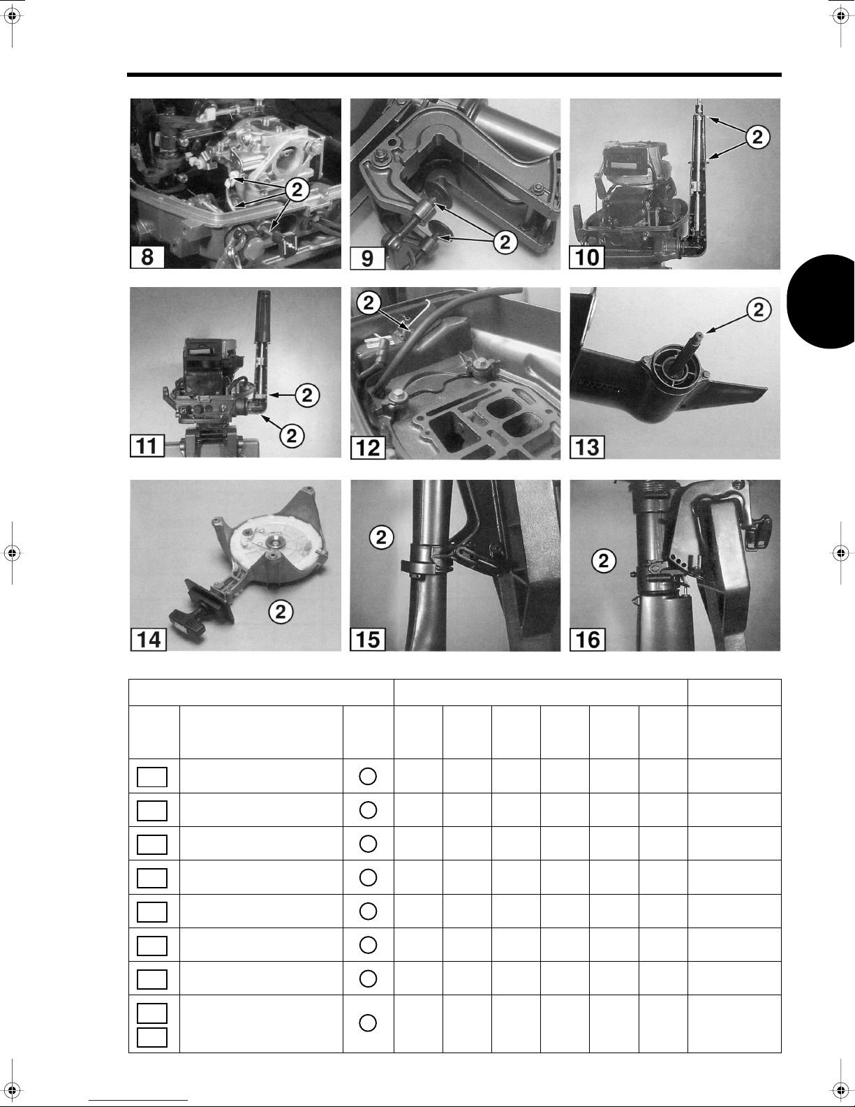
LUBRICATION CHART
NOTE
Recommended intervals are for freshwater
recreational operation. Decrease interval by 50% for
salt water and severe duty (commercial) operation.
Lube Type: = Low Temperature Lithium Grease
1
= Genuine Grease or equivalent Friction
Surface Marine Grease
3
= Non-flammable solvent
4
= Genuine Gear Oil or API Grade GL5 #80 - #90
T1943
T1942
T1944 T1945
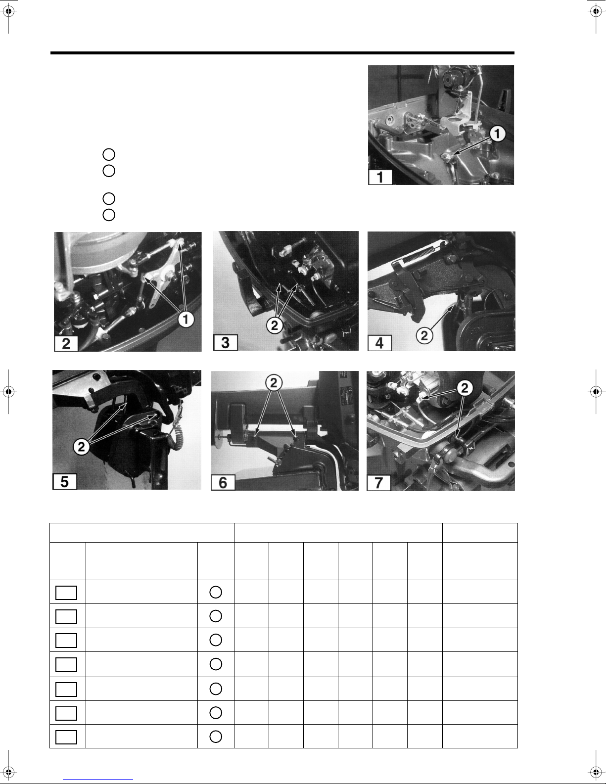
Lubrication Points and Lubricant Engine Model Frequency
Fig. Location
1
2
3
4
5
6
7
2-20
Shift Lever Mechanism •••••• 50
Throttle Linkage • • • 50
Throttle Cable • • 50
Tilt Stopper •••••• 50
Bracket Bolt •••••• 50
Bracket Shaft ••••• 50
Carburetor Choke Rod ••••• 50
Lube
Type
1
1
2
2
2
2
2
2.5
3.5 5
8
9.8
9.9
15
18
25
30 40
Hours
1-/ 2-Cylinder
GENERAL SERVICE INFORMATION
T1955
T1956
T1957
T1949
T1801
T1950
T1953
T1951
T1954
Lubrication Points and Lubricant Engine Model Frequency
Fig. Location
8
9
10
11
12
13
14
15
Choke Mechanism •••••• 50
Clamp Screw •••••• 50
Grip • • • • • 50
Handle •••••• 50
Hook Lever Mechanism • • • • • 50
Propeller Shaft •••••• 50
Recoil Starter •••••• 50
Reverse Lock •••••• 50
16
1-/ 2-Cylinder
Lube
Type
2
2
2
2
2
2
2
2
2.5
3.5 5
8
9.8
9.9
15
18
25
30 40
Hours
2-21
 Loading...