

Tohatsu MWX50D2 User Manual
GB
OWNER’S MANUAL
F
MANUEL
DE L’UTILISATEUR
ES
MANUAL
DEL PROPIETARIO
MX 50D
MWX 50D
OB No.003-11098-0
2
2
MX 50D
2
MWX 50D
2
OB No.003-11098-0
OWNER’S
MANUAL

READ THIS MANUAL BEFORE USING THE OUTBOARD MOTOR. FAILURE TO FOLLOW THE
INSTRUCTIONS AND SAFETY PRECAUTIONS IN THIS MANUAL CAN RESULT IN SERIOUS
INJURY OR DEATH. KEEP THIS MANUAL IN A SAFE LOCATION FOR FUTURE REFERENCE.
Copyright © 2011 Tohatsu Corporation. All rights reserved. No part of this manual may
be reproduced or transmitted in any from or by any means without the express written
permission of Tohatsu Corporation.

YOUR TOHATSU OUTBOARD MOTOR
OWNER REGISTRATION AND IDENTIFICATION
Upon purchasing this product, be sure that the WARRANTY CARD is correctly and completely filled out and mailed to the addressee noted there on. This WARRANTY CARD
identifies you as the legal owner of the product and serves as your warranty registration.
TO THE EXTENT PERMITTED BY APPLICABLE LAW, YOUR OUTBOARD MOTOR WILL
NOT BE COVERED BY THE APPLICABLE LIMITED WARRANTY, IF THIS PROCEDURE IS
NOT FOLLOWED.
PRE-DELIVERY CHECK
Be sure that the product has been checked by an authorized TOHATSU dealer before you
take delivery.
Limited Warranty
Please refer to the TOHATSU outboard motor Limited warranty provided to you with this
product, the terms and conditions of which, as amended from time to time, are incorpo-
rated by reference into the manual.
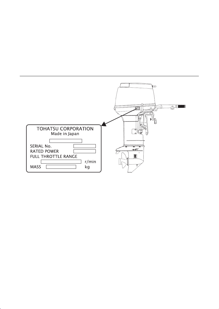
Serial Number
In the space below, please record the outboard motor's serial number (indicated both on
the bottom cowl and on the cylinder block). The serial number will be needed in ordering
spare parts and the event of theft or to quickly identifying the outboard motor type.
Serial Number :
To You, Our Customer
Thank you for selecting a TOHATSU outboard motor. You are now the proud owner of an
excellent outboard motor that will service you for many years to come.
This manual should be read in its entirety and the inspection and maintenance procedures
described later in this manual should be followed carefully. Should a problem arise with the
outboard motor, please follow the troubleshooting procedures listed at the end of this
manual. If the problem persists, contact an authorized TOHATSU service shop or dealer.
We hope you will enjoy your outboard motor and wish you good luck in your boating
adventures.
TOHATSU CORPORATION

CONTENTS
GENERAL SAFETY INFORMATION. . . . . . . . . . . . . . . . . . . . . . . . . . . . . . . . 8
1. SPECIFICATIONS . . . . . . . . . . . . . . . . . . . . . . . . . . . . . . . . . . . . . . . . . . . . . 10
2. NAMES OF PARTS . . . . . . . . . . . . . . . . . . . . . . . . . . . . . . . . . . . . . . . . . . . . 11
3. INSTALLATION . . . . . . . . . . . . . . . . . . . . . . . . . . . . . . . . . . . . . . . . . . . . . . . 12
1. Mounting the outboard motor on boat . . . . . . . . . . . . . . . . . . . . . . . . . . .12
2. Propeller Selection. . . . . . . . . . . . . . . . . . . . . . . . . . . . . . . . . . . . . . . . . . . 14
4. PRE-OPERATING PREPARATIONS . . . . . . . . . . . . . . . . . . . . . . . . . . . . . .15
1. Recommended gasoline types . . . . . . . . . . . . . . . . . . . . . . . . . . . . . . . . .15
2. Recommended engine oil . . . . . . . . . . . . . . . . . . . . . . . . . . . . . . . . . . . . . 17
3. Break-in . . . . . . . . . . . . . . . . . . . . . . . . . . . . . . . . . . . . . . . . . . . . . . . . . . . 19
5. ENGINE OPERATION . . . . . . . . . . . . . . . . . . . . . . . . . . . . . . . . . . . . . . . . . .20
1. Starting. . . . . . . . . . . . . . . . . . . . . . . . . . . . . . . . . . . . . . . . . . . . . . . . . . . . 20
2. Warming up the engine . . . . . . . . . . . . . . . . . . . . . . . . . . . . . . . . . . . . . . . 23
3. Forward and reverse . . . . . . . . . . . . . . . . . . . . . . . . . . . . . . . . . . . . . . . . . 24
4. Shallow water running . . . . . . . . . . . . . . . . . . . . . . . . . . . . . . . . . . . . . . . . 26
5. Stopping the engine. . . . . . . . . . . . . . . . . . . . . . . . . . . . . . . . . . . . . . . . . .27
6. Trim angle . . . . . . . . . . . . . . . . . . . . . . . . . . . . . . . . . . . . . . . . . . . . . . . . .28
7. Mooring with the engine tilted up . . . . . . . . . . . . . . . . . . . . . . . . . . . . . . .30
6. REMOVING AND CARRYING THE OUTBOARD MOTOR. . . . . . . . . . . . . . 32
1. Removing the outboard motor. . . . . . . . . . . . . . . . . . . . . . . . . . . . . . . . . .32
2. Carrying the outboard motor . . . . . . . . . . . . . . . . . . . . . . . . . . . . . . . . . . .32
3. Storing the outboard motor . . . . . . . . . . . . . . . . . . . . . . . . . . . . . . . . . . . .33
7. TRAILERING . . . . . . . . . . . . . . . . . . . . . . . . . . . . . . . . . . . . . . . . . . . . . . . . . 35
8. ADJUSTMENT . . . . . . . . . . . . . . . . . . . . . . . . . . . . . . . . . . . . . . . . . . . . . . . .36
1. Trim tab adjustment. . . . . . . . . . . . . . . . . . . . . . . . . . . . . . . . . . . . . . . . . . 36
2. Steering load adjustment. . . . . . . . . . . . . . . . . . . . . . . . . . . . . . . . . . . . . . 37
3. Throttle grip turning load adjustment. . . . . . . . . . . . . . . . . . . . . . . . . . . . . 38
9. INSPECTION AND MAINTENANCE . . . . . . . . . . . . . . . . . . . . . . . . . . . . . . . 39
1. Daily inspection . . . . . . . . . . . . . . . . . . . . . . . . . . . . . . . . . . . . . . . . . . . . .40
2. Periodic inspection . . . . . . . . . . . . . . . . . . . . . . . . . . . . . . . . . . . . . . . . . .44
3. Off-season storage . . . . . . . . . . . . . . . . . . . . . . . . . . . . . . . . . . . . . . . . . .49
4. Pre-season check . . . . . . . . . . . . . . . . . . . . . . . . . . . . . . . . . . . . . . . . . . . 50
5. Checking after striking underwater object. . . . . . . . . . . . . . . . . . . . . . . . . 51
6. If the engine becomes submerged in water. . . . . . . . . . . . . . . . . . . . . . . . 51
7. Precautions in cold weather. . . . . . . . . . . . . . . . . . . . . . . . . . . . . . . . . . . . 52
10. TROUBLESHOOTING . . . . . . . . . . . . . . . . . . . . . . . . . . . . . . . . . . . . . . . . . . 53
11. TOOL KIT AND SPARE PARTS . . . . . . . . . . . . . . . . . . . . . . . . . . . . . . . . . . 55
12. OPTIONAL ACCESSORIES . . . . . . . . . . . . . . . . . . . . . . . . . . . . . . . . . . . . . 56
13. PROPELLER TABLE . . . . . . . . . . . . . . . . . . . . . . . . . . . . . . . . . . . . . . . . . . . 57
14. WIRING DIAGRAM . . . . . . . . . . . . . . . . . . . . . . . . . . . . . . . . . . . . . . . . . . . . 58
INDEX
7
GENERAL SAFETY INFORMATION
1. SPECIFICATIONS
2. NAMES OF PARTS
3. INSTALLATION
4. PRE-OPERATING PREPARATIONS
5. ENGINE OPERATION
6.
REMOVING AND CARRYING THE OUTBOARD MOTOR
7. TRAILERING
8. ADJUSTMENT
9. INSPECTION AND MAINTENANCE
1
2
3
4
5
6
7
8
9
10. TROUBLESHOOTING
11. TOOL KIT AND SPARE PARTS
12. OPTIONAL ACCESSORIES
13. PROPELLER TABLE
14. WIRING DIAGRAM
10
11
12
13
14
8
DANGER
WARNING
CAUTION
WARNING
GENERAL SAFETY INFORMATION
NOTICE : DANGER/WARNING/CAUTION/Note
Before installing, operating or otherwise handling your outboard motor, be sure to thoroughly read and understand this Owner's Manual and carefully follow all of the instruc-
tions. Of particular importance is information preceded by the words "DANGER,"
"WARNING," "CAUTION," and "Note." Always pay special attention to such information to
ensure safe operation of the outboard motor at all times.
Failure to observe will result in severe personal injury or death, and possibly property damage.
Failure to observe could result in severe personal injury or death, or property damage.
Failure to observe could result in personal injury or property damage.
Note
This instruction provides special information to facilitate the use or maintenance of the outboard
motor or to clarify important points.
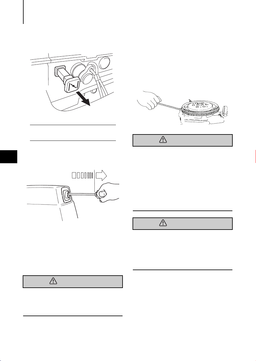
EMERGENCY STOP SWITCH
The Emergency Stop Switch will stall the outboard motor when the stop switch tether is
pulled off. This stop switch tether can be attached to the operator of the outboard motor
to minimize or prevent injuries from the propeller in case the operator falls overboard.
We highly recommend use of the Emergency Stop Switch tether.
Accidental activation of the Emergency Stop Switch (such as the tether being pulled out in
heavy seas) could cause passengers to lose their balance and even fall overboard, or it
could result in loss of power in heavy seas, strong currents, or high winds. Loss of control
while mooring is another potential hazard.
To minimize accidental activation of the Emergency Stop Switch, the 500 mm (20 inch.) stop
switch tether is coiled and can extended to a full 1,300 mm (51 inch.).
SAFE OPERATION OF BOAT
WARNING
As the operator/driver of the boat, you are responsible for the safety of those aboard and
those in other boat around yours, and for following local boating regulations. You should
be thoroughly knowledgeable on how to correctly operate the boat, outboard motor, and
accessories. To learn about the correct operation and maintenance of the outboard motor,
please read through this manual carefully.
It is very difficult for a person standing or floating in the water to take evasive action should
he or she see a power boat heading in his /her direction, even at a slow speed. Therefore,
when your boat is in the immediate vicinity of people in the water, the outboard motor
should be shifted to neutral and shut off.
SERIOUS INJURY IS LIKELY IF A PERSON IN THE WATER MAKES CONTACT WITH A MOV-
ING BOAT, GEAR HOUSING, PROPELLER, OR ANY SOLID DEVICE RIGIDLY ATTACHED TO
A BOAT OR GEAR HOUSING.
SERVICING, REPLACEMENT PARTS & LUBRICANTS
We recommend that only an authorized service shop perform service or maintenance on
this outboard motor. Be sure to use genuine parts, genuine lubricants, or recommended
lubricants.
9
MAINTENANCE
As the owner of this outboard motor, you should be acquainted with correct maintenance
procedures. It is the operator's responsibility to perform all safety checks and to ensure
that all lubrication and maintenance instructions are complied with for safe operation.
Please comply with all instructions concerning lubrication and maintenance. You should
take the engine to an authorized dealer or service shop for periodic inspection at the prescribed intervals.
Correct periodic maintenance and proper care of this outboard motor will reduce the
chance of problems and limit overall operating expenses.
MOUNTING
Outboard motor mounting must be performed by trained service person(s) using lift or
hoist with sufficient capacity.

SPECIFICATIONS10
SPECIFICATIONS
X50D2MF, WX50D2MF
Item MODEL
Overall Length mm (in) 1,143 (45.0) 1,145 (45.1)
1
Overall Width mm (in) 384 (15.1) 384 (15.1)
S mm (in) 1,225 (48.2)
Overall Height
Tra nsom Height
Weight
Output kW (Hp) 36.8 (50)
Max. Operating Range rpm 5,150-5,850
Number of Cylinders 3
Piston Displacement mL (Cu in) 697 (42.53)
Bore x Stroke mm (in) 68 x 64 (2.68 x 2.52)
Exhaust System Through hub exhaust
Engine Lubrication Premixed Fuel
Fuel mixing Ratio 50 : 1
Cooling System Forced water cooling
Starting System Manual
Ignition System Flywheel Magneto C.D. Ignition
Spark Plugs NGK B8HS-10
Tri m Po sition 6
Engine Oil Genuine Motor Oil or recommended one (TCW-III)
Gear Oil* approx. 500mL approx. 700mL
Fuel Tank Capacity L (US gal) 25 (6.6)
Engine Oil Capacity L (US gal)
Gear Reduction Ratio 1.85 (13 : 24) 1.92 (12 : 23)
Fuel
* Genuine Gear Oil or API GL5, SAE #80 to #90
Remark: This specifications might change without a previous notice.
L mm (in) 1,352 (53.2) 1,413 (55.6)
LL mm (in) 1,427 (56.1)
UL mm (in) 1,479 (58.2)
S mm (in) 403 (15.9)
L mm (in) 530 (20.9) 550 (21.7)
LL mm (in) 570 (22.5)
UL mm (in) 657 (25.9)
S kg (lb) 72 (159)
L kg (lb) 73.5 (162) 79 (174)
LL kg (lb) 74 (163)
UL kg (lb) 75 (165)
Unleaded regular gasoline pump posted 87 Octane (research octane
rating of 91)
X50D2MF WX50D2MF
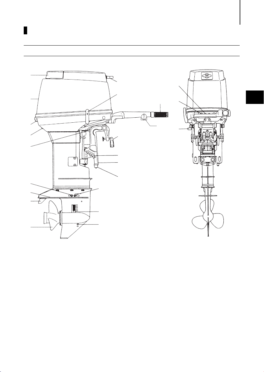
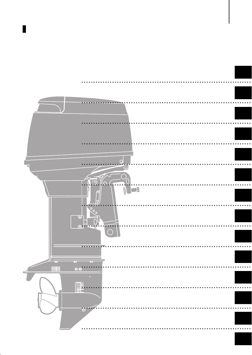
NAMES OF PARTS
X50D2MF, WX50D2MF
1
2
NAMES OF PARTS 11
19
18
20
21
16
2
3
4
5
6
7
8
9
1 Tilt Handle
2 Top C o w l
3 Hook Lever
4 Water Check Port
5 Reverse Lock Lever
6 Water Plug
7 Anti-ventilation Plate
8 Trim Ta b
9 Propeller
15
14
13
22
12
11
10
10 Oil Plug (lower)
11 Water Strainer
12 Oil Plug (upper)
13 Clamp Bracket
14 Thrust Rod
15 Clamp Screw
16 Throttle Grip
17 Adjust Nut
18 Shift Lever
17
19 Starter Handle
20 Stop Switch
21 Choke Knob
22 Anode
5
INSTALLATION12
WARNING
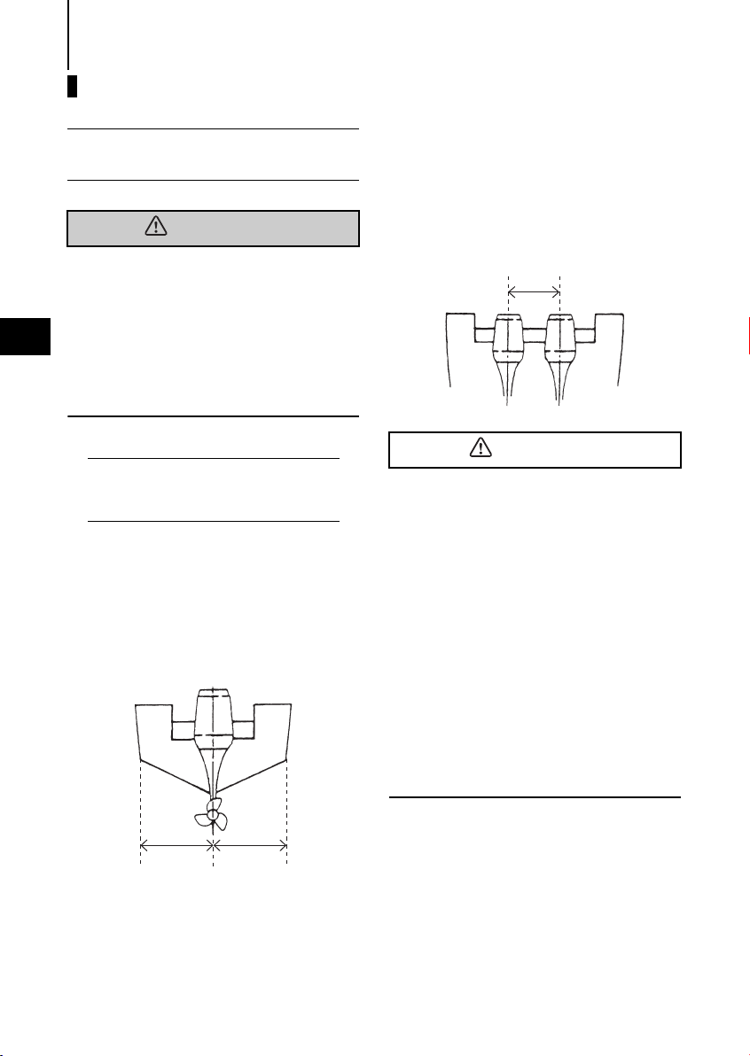
470 - 660 mm
(18.5 - 26.1 in)
CAUTION
INSTALLATION
1. Mounting the outboard motor on boat
Most boats are rated and certified in terms
of their maximum allowable horsepower,
as shown on the boat’s certification plate.
Do not equip your boat with an outboard
motor that exceeds this limit. If in doubt,
3
contact your dealer.
Do not operate the outboard motor until it
has been securely mounted on the boat in
accordance with the instructions below.
Note
Consult your authorized dealer to receive
the proper instructions or ask your dealer to
mount the motor as necessary.
Installation
Single-engine Installation
Position the outboard engine at the exact
center of the stern, and mount it using a
cushioning pad or plate.
Twin-engine Installation
When installing two outboard engines, be
sure to keep an interval of approximately
470 - 660 mm (18.5 - 26 in) between the
two.
Before beginning the running test, check
that the boat with maximum capacity
loading floats on the water in a proper
attitude. Check the position of water
surface on the driveshaft housing. If the
water surface is near the bottom cowling, in high waves, water may enter the
engine cylinders.
Incorrect outboard motor mounting
height or existence of underwater
object(s), such as hull bottom design,
bottom surface conditions or underwater accessories, can cause water spray
possibly reaching the engine through an
opening of the bottom cowling during
cruising. Exposing engine to such conditions for extended periods can lead to
severe engine damage.
AA
INSTALLATION 13
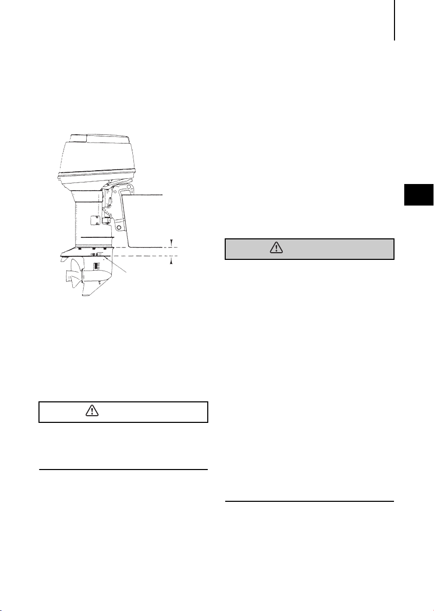
Anti-ventilation Plate
10 ~ 30mm (0.4~1.2 in.)
CAUTION
WARNING
Tra n s o m Height
Install the engine with the Anti-ventilation
Plate at a level 10~30mm (0.4~1.2in.)
below the bottom of the boat.
Transom Matching
Be sure that anti ventilation plate of the
outboard is below the water surface when
running with wide open throttle.
In case the above condition cannot be met
due to the shape of your boat, please con-
sult your authorized dealer.
Overheating may occur if the Anti-ventilation Plate is at a level higher than the bottom of the boat, as a result of a lack of
cooling water.
If the height difference exceeds 10~30mm
(0.4~1.2 in) engine power performance is
likely to be reduced as a result of
increased water resistance to the gear
case assembly.
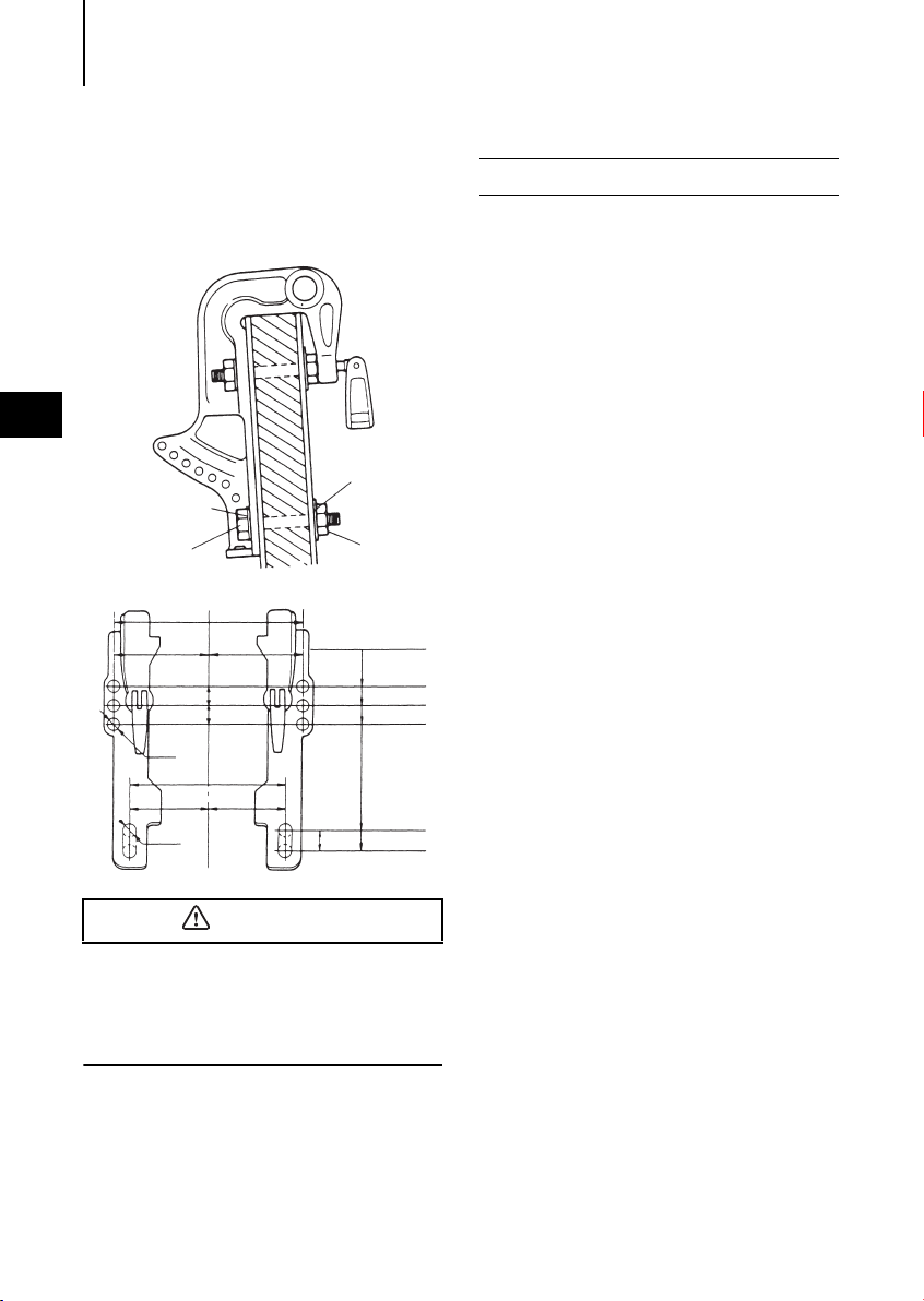
Attaching the Clamp Bracket
After positioning the Clamp Bracket, fix it
with clamp screw then drill four holes in
the transom board, matching the holes in
the Clamp Bracket. Secure the engine with
the supplied bolts (M12 x 105mm) and
nuts. Be sure to use the washers. Use the
larger diameter washers inside of the transom board and use the small diameter
washers outside of the clamp bracket.
The mounting holes may be drilled beforehand by referring to the dimensional drawing.
Mounting the outboard motor without
following this manual can lead to unsafe
conditions such as poor maneuverability, going out of control or fire disaster.
Loose clamp screws and/or mounting
bolts can lead to the release or displacement of the outboard motor, possibly
resulting in lost of control and/or serious
personal injury. Be sure that fasteners
are tightened to the specified torque (30
Nm (3.0kgf) 13ft·lb). Check the fasteners
for tightness from time to time.
Be sure to use outboard mounting fas-
teners included in the outboard motor
package or their equivalents in terms of
size, material, quality and strength.
Tighten fasteners to the specified torque
(30 Nm (3.0kgf) 13ft·lb). Test cruise to
check if fasteners are tightened
securely.
Outboard motor mounting must be per-
formed by trained service person(s)
using lift or hoist with sufficient capacity.
3
INSTALLATION14
Washer
(large diameter)
Bolt
(12mm x length 105mm)
Washer
(small diameter)
Nut
Top of tr a n som
CAUTION
Clamp Bracket
Dimensional Drawing
Manual tilting type
3
117(4.61”)
ø13
ø13
234(9.21”)
117(4.61”)
25(0.98”)
25(0.98”)
204(8.03”)
102(4.02”)102(4.02”)
26(1.02”
39(1.54”)
64(2.52”)
89(3.50”)
222(8.74”)
)
248(9.76”)
2. Propeller Selection
A propeller must be selected so that the
engine rpm measured at wide open throttle while cruising is within the max. operating range; 5,150 to 5,850 rpm
For genuine propellers, refer to PROPELLER TABLE (p. 57).
Mounting bolts should be installed with the
bolt head at inside surface of the transom.
Mounting bolts installed with the threaded
end at the inside surface of the transom
can cause personal injury.

PRE-OPERATING PREPARATIONS 15
DANGER
CAUTION
PRE-OPERATING PREPARATIONS
1. Recommended gasoline types
Consult an authorized dealer for details on
handling of gasoline, if necessary.
Gasoline and its vapors are very flammable
and can be explosive.
When carrying a fuel tank containing gasoline:
Close the air vent screw of fuel tank cap,
or gasoline vapor will be emitted
through the air vent screw, creating a
fire hazard.
Do not smoke.
When or before refueling :
Stop the engine, and do not start the
engine during refueling.
Do not smoke.
Be careful not to overfill fuel tank. Wipe
up any spilled gasoline immediately.
When or before cleaning the gasoline tank :
Dismount fuel tank from the boat.
Place the fuel tank away from every
source of ignition, such as sparks or
open flames.
Do the work outdoors or in well venti-
lated area.
Wipe up any spilled gasoline immedi-
ately.
Use of low-quality gasoline results in a
short engine life as well as starting difficulties and other engine problems.
We recommend use for Fuel stabilizer.
Use of unleaded gasoline
Use a major brand of automotive unleaded
gasoline with a minimum posted octane
rating of 91RON. Automotive gasoline that
contain fuel injector cleaner are preferred
for added internal engine cleanliness.
Leaded gasoline is acceptable in areas
where unleaded gasoline is not available.
4
After cleaning gasoline tank :
Wipe up any spilled gasoline immedi-
ately.
If the fuel tank is disassembled for
cleaning, reassemble carefully. Imperfect assembly may cause a fuel leak,
possibly leading to fire or explosion.
Dispose of aged or contaminated gaso-
line in accordance with local regulations.
PRE-OPERATING PREPARATIONS16
CAUTION
WARNING
Use of alcohol free gasoline
Use of gasoline containing alcohol can
cause engine starting and/or operating difficulties, wear of and damages to engine
parts, and deterioration of chemical parts,
which may lead to shortening of your outboard motor’s life.
Note
The adverse effect caused by the alcohol
4
content is more severe with methanol than
with ethanol.
TOHATSU recommend the use of gasoline
if its ethanol content is less than 10% or
methanol content is less than 5%, only in
case alcohol free gasoline is not available.
The alcohol component of the gasoline
absorbs moisture from the air, which may
disturb regular fuel flow in the fuel system,
and also accelerate rusting of engine
parts.
Mixing of the moisture in the engine oil can
also deteriorate the properties of the lubricant.
If the use of gasoline containing alcohol is
inevitable, or presence of alcohol is sus-
pected in the gasoline, it is strongly recommended to add a filter that has water
separating capability, and check the fuel
system for leaks and mechanical parts for
corrosion and abnormal wear more frequently.
And, in case any of s
uch abnormality is
found, discontinue the use of such gaso-
line and contact our dealer immediately.
Damages resulting from the use of gasolines that contain alcohol are not covered
under the limited warranty.
Fuel tank capacity : 25 liters (6.6 U.S. gal)
Fuel Tank : When using a fixed fuel tank in
place of genuine fuel tank, it is recommended to select a one with a structure
facilitating interior cleaning.
Do not fill the fuel tank over capacity. The
rise of gasoline temperature may cause
gasoline to expand which, if overfilled, may
leak through air vent screw when it is open.
Leaking gasoline is a dangerous fire hazard.
PRE-OPERATING PREPARATIONS 17
CAUTION
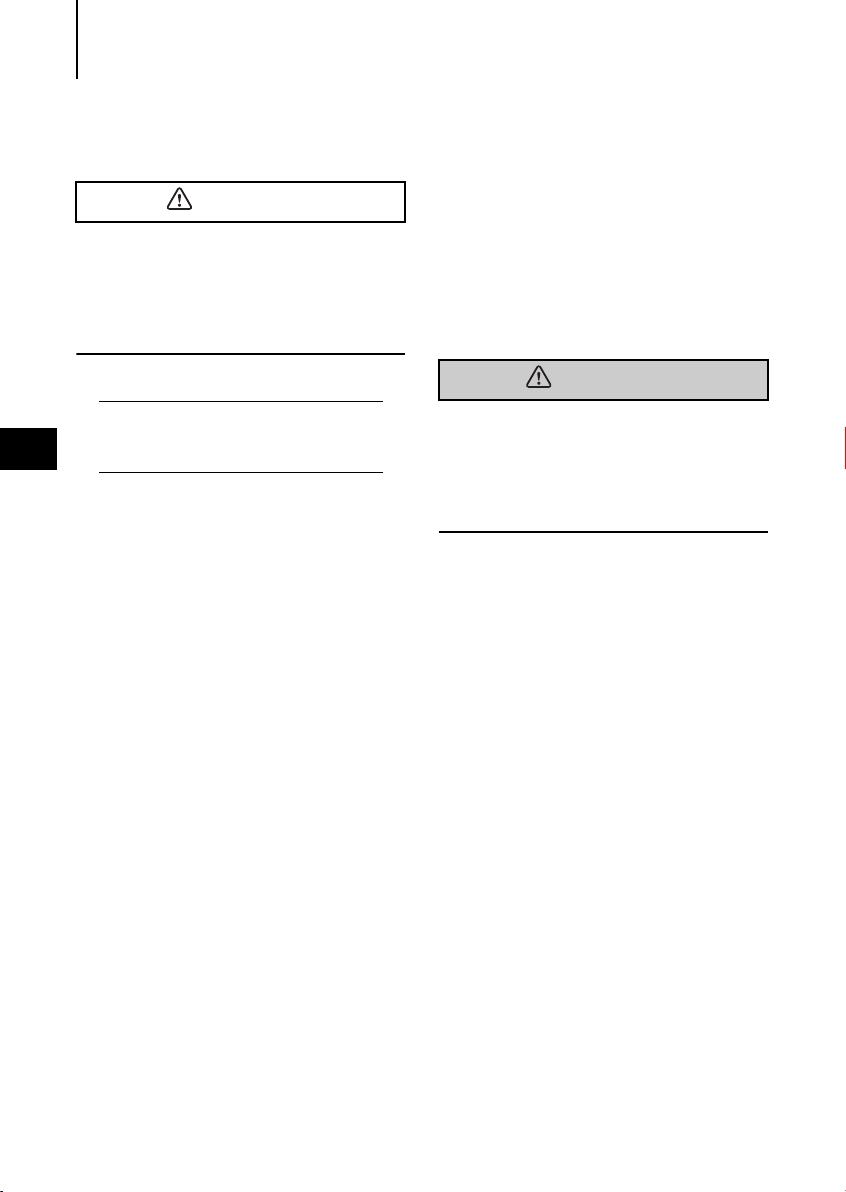
Fuel by Oil Mixing (1:25, 1:50)
Gasoline
Oil
2. Recommended engine oil
Use a genuine engine oil or recommended
one (TCW3). Refer to your Distributor.
Will not recommend use of other two
stroke engine oil.
Do not mix different brands of oil.
Mixing different brands of oil, or different
types of oil even if the brand is the same,
may cause gelling, resulting in possible filter screen blockage. This could result in
serious engine damage because of
impaired lubrication performance.
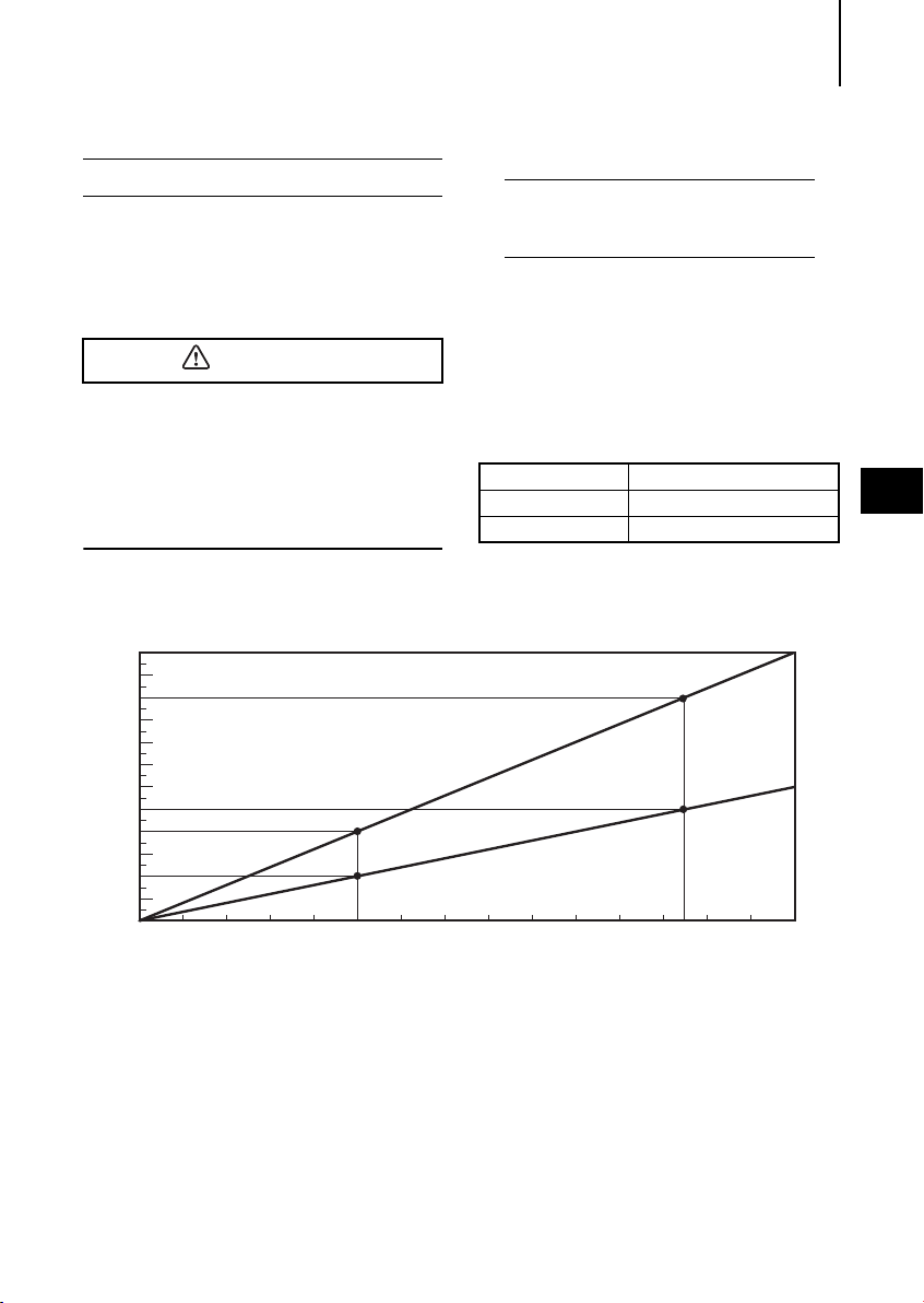
1.2L
1.1L
1.0L
0.9L
0.8L
0.7L
0.6L
0.5L
0.4L
0.3L
0.2L
0.1L
0
2L 25L 30L
10L
(0.4:10)
(0.2:10)
Note
Use of engine oils that do not meet these
requirements will result in reduced engine
life, and other engine problems.
Add engine oil into fuel oil tank. The mixing
ratio with gasoline is 1 : 50 (one part oil
and 50 parts gasoline). Mix well by hand.
The mixing ratio during break-in running is
1 : 25.
Mixing Ratio
Engine Oil : Gasoline
During break-in 1 : 25
After break-in 1 : 50
(1:25)
1:25
(0.5:25)
1:50
4
PRE-OPERATING PREPARATIONS18
CAUTION
WARNING
Engine oil – gasoline mixing
procedure
For quantities of engine oil and gasoline to
be pre-mixed, refer to table in Recommended engine oil (p. 17).
Do not use other than two stroke engine
oil with specified grade, or the engine
may be damaged.
Do not use fuel prepared in other than
specified mixing ratio.
- Lack of engine oil can cause severe
4
engine trouble such as piston seizure.
- Excess of engine oil can shorten spark
plug life, and/or cause increase of noxious exhaust.
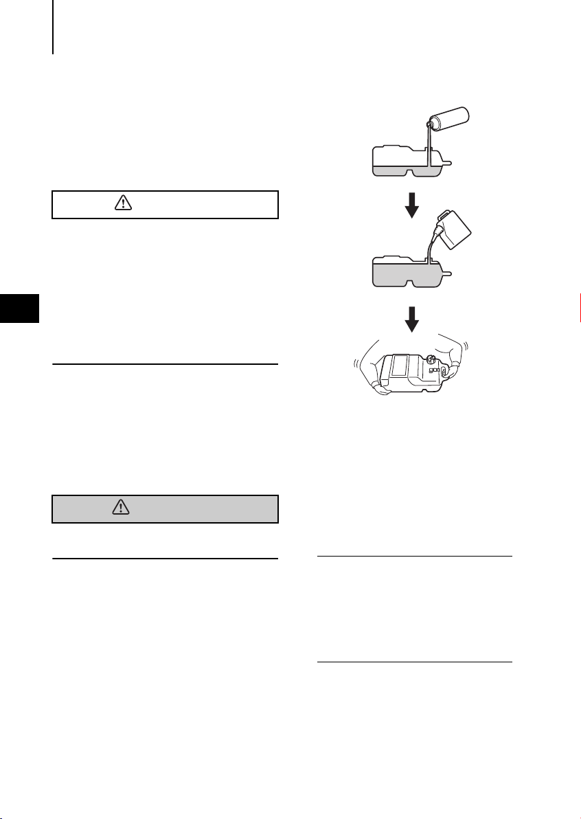
When portable fuel tank is used for
operation of outboard motor(s):
1
Pour engine oil into fuel tank, and then,
gasoline.
2
Put cap on the tank, and close tightly.
3
Close air vent plug tightly.
Loose cap or air vent plug can cause leak
of fuel during shaking the tank.
4
Shake the tank to mix engine oil and
gasoline well and even.
When fuel tank built in the boat is
used for operation of outboard
motor(s):
1
Prepare separate fuel container for premixing.
2
Pour engine oil into fuel container, and
then, gasoline.
3
Put cap on the container, and close
tightly.
4
Shake the container to mix engine oil
and gasoline well and even.
5
Pour the mixture into fuel tank.
Notes
It is recommended to pre-mix by using
separate fuel container. Attempting to
pre-mix in the fuel tank built-in the boat
can make the mixture uneven.
If built-in fuel tank is used for mixing,
pour engine oil into the tank little by little
while putting gasoline into the tank.
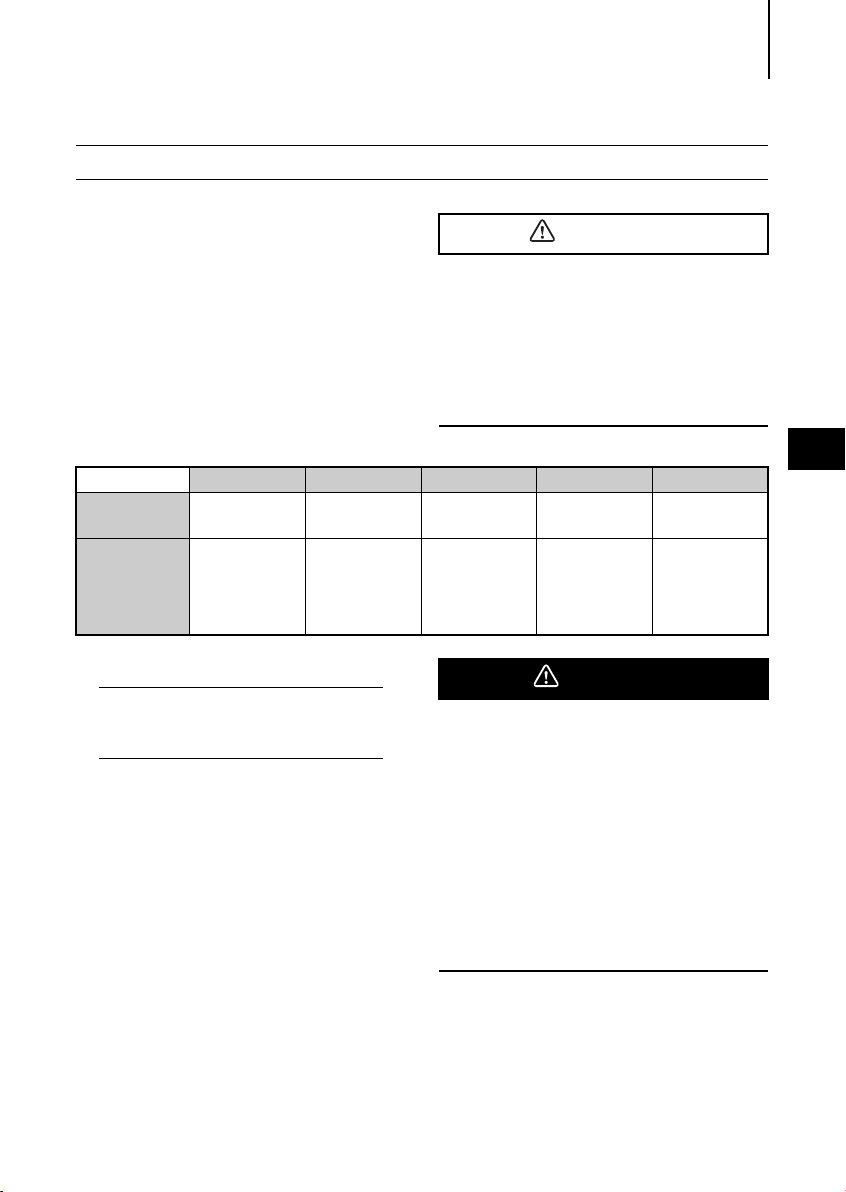
3. Break-in
CAUTION
DANGER
Your new outboard motor and lower unit
require break-in for the moving components according to the conditions
described in the following time table.
1-10min 10min-2hrs 2-3hrs 3-10hrs After 10hrs
Throttle
Position
Speed
Idle
Less than 1/2
throttle
Approx.
3,000 rpm max
PRE-OPERATING PREPARATIONS 19
Operating the outboard motor without
break-in can shorten service life of the
product.
If any abnormality is experienced during
the break-in:
Discontinue the operation immediately.
Have the dealer check the product and
take proper action(s) if necessary.
Less than 3/4
throttle
Full throttle run
allowed for 1 min
every 10 min
3/4 throttle
Approx.
4,000 rpm.
Full throttle run
allowed for 2 min
every 10 min
Full throttle
available
4
Note
Proper break-in allows outboard motor to
deliver it full performance for longer service
life.
Fuel mix ratio for break-in
Gasoline 25: Genuine Engine Oil 1
25:1 when using genuine engine oil or
the recommended one (TCW3).
Do not operate the outboard motor in
closed area or area with no forced ventilation.
Exhaust gas emitted by this outboard
motor contains carbon monoxide that will
cause death if inhaled continuously. Inhaling the gas initially causes symptoms such
as feeling of sickness, drowsiness and
headache.
During operation of the outboard motor :
Keep peripheral area well ventilated.
Always attempt to stay on the windward
side of emission.
ENGINE OPERATION20
WARNING
WARNING
CAUTION
ENGINE OPERATION
1. Starting
In case engine starts in gear, do not start
cruising. Stop engine immediately and consult an authorized dealer.
Note
The engine will not start unless the switch
lock has been properly connected into the
emergency stop switch.
Do not operate the engine with gear case
5
out of water.
Severe personal injury, or engine damage
will result.
Never fill up portable fuel tanks on board to
avoid fire or explosion resulting from
spilled gasoline. If gasoline is ever spilled
on board, wipe it up thoroughly. Fuel tanks
must always be filled up on land.
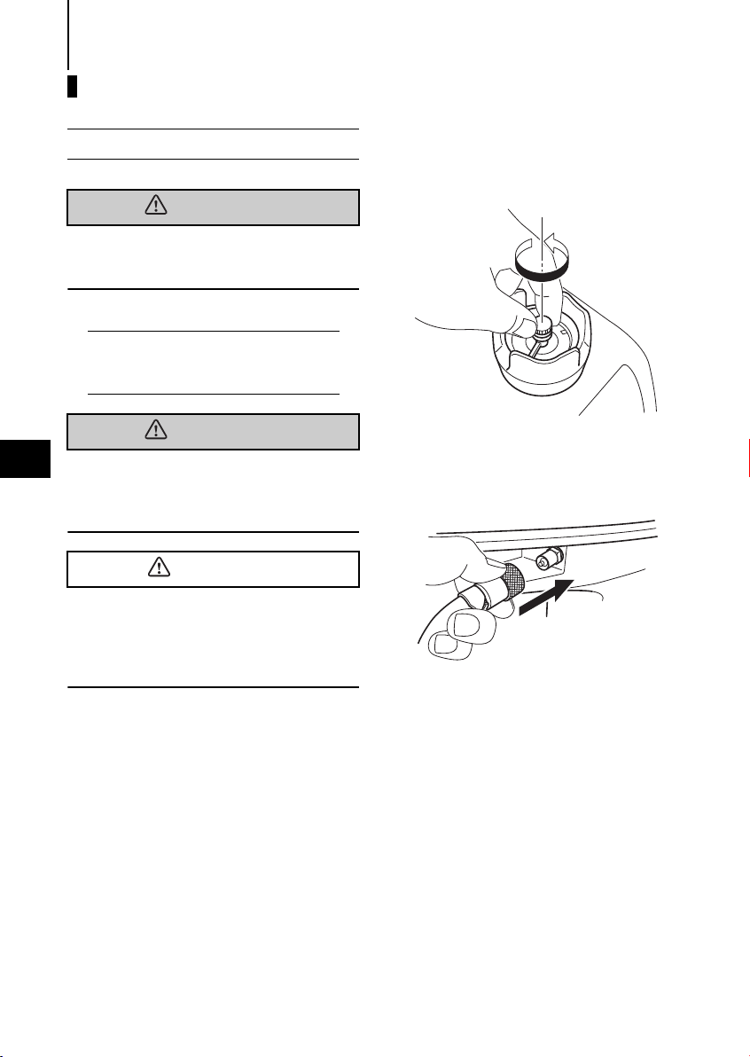
Preparations
1
Loosen the air vent screw on the tank
cap.
2
Connect the fuel connector to the
engine.
3
Lock
Stop switch
Engine side
Fuel tank side
CAUTION
Install a lock in the stop switch.
4
Feed fuel to the carburetor by squeez-
ing the primer bulb until firm.
ENGINE OPERATION 21
Starting
F type
1
Set the shift lever to Neutral
If the engine starts in gear, do not use it.
Contact an authorized dealer.
Note
Start-in-gear protection prevents engine
from starting at other than neutral shift. Ingear starting of engine will move the boat
immediately, potentially leading to falling
down or causing passenger(s) to be thrown
overboard due to inertial force.
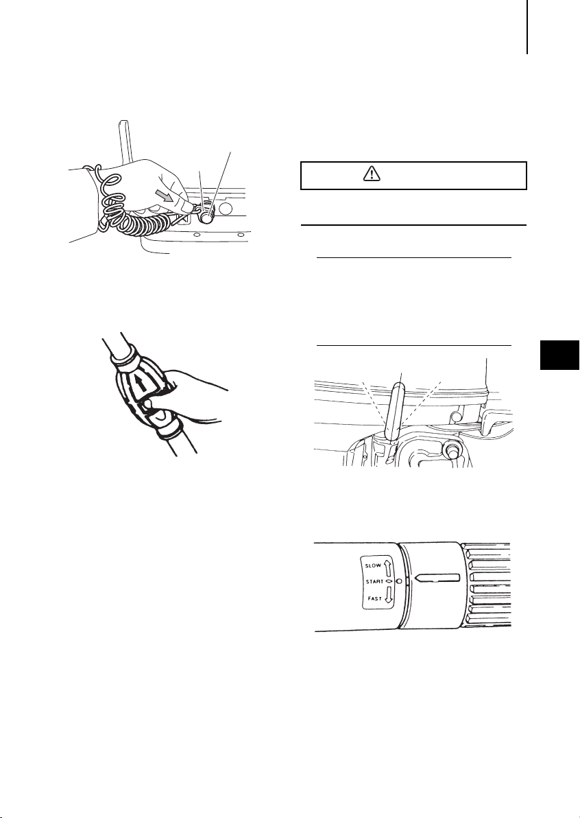
R
2
Turn the throttle grip so that the indica-
N
F
tor line meets the "START" mark.
5
5
WARNING
WARNING
WARNING
ENGINE OPERATION22
3
Pull the choke knob fully.
Note
Operation of the choke knob is not required
if the engine is warm.
4
Pull the starter rope slowly until resis-
tance is met.
Give it a sharp tug to start the engine.
Manual Rope Start - - - in case of
trouble with the Recoil Starter
Wind the starter rope around the flywheel
a few turns. Give it a sharp tug to start the
engine. Use a socket wrench or similar to
get a firm grip on the end of the rope.
Be careful that your clothes or other items
do not get caught in the rotating engine
parts.
To prevent accident and injury, do not reattach the recoil starter after the engine
has been started using the emergency
starter rope. Be sure to put the top cowl
back on.
Immediately contact an authorized dealer
when reaching shore.
5
Turn the handle grip to its original posi-
tion gradually once the engine has
started.
6
Push back the choke knob slowly.
7
Carefully turn the throttle grip to
“SLOW”.
Do not operate the engine with gear case
out of water.
Severe personal injury, or engine damage
will result.
Be sure that no bystander(s) is within 2
meters from back of starting operator.
Do not operate the outboard motor with
top cowl removed from the power unit,
or contacting turning flywheel which can
lead to serious personal injury.
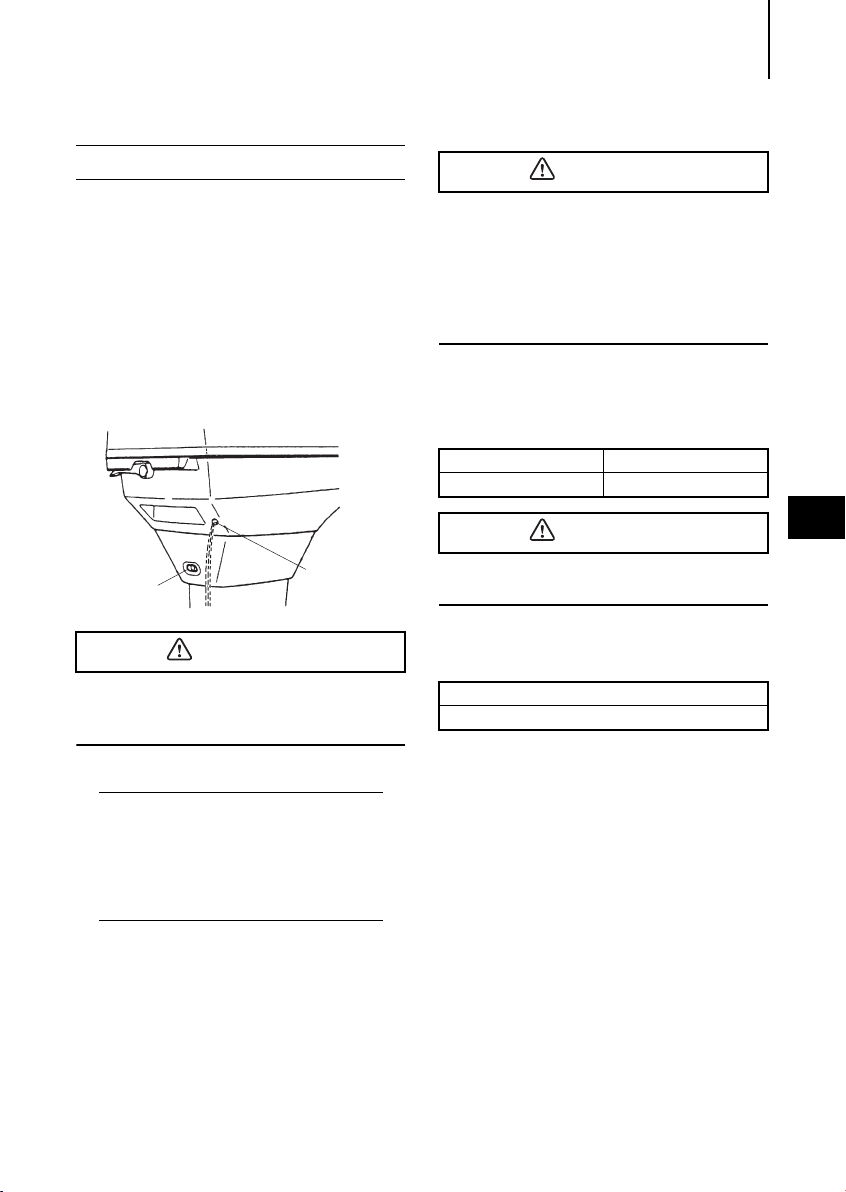
2. Warming up the engine
Idle port
Cooling water
check port
CAUTION
CAUTION
CAUTION
ENGINE OPERATION 23
Before driving the boat, let the engine run
at low speed for approximately three minutes to let it warm and allow the oil to circulate through the machine. If the engine is
not warmed up beforehand, the engine life
will shorten greatly. During the warm-up
operation, confirm that cooling water is
discharged from the check port and idle
port.
Be sure to warm up engine well before
starting cruise. Operating cold engine can
give damage to it.
Note
Idle speed may be higher during warming
up of engine. If shifted to Forward or reverse
during warming up, it may be difficult to shift
back to neutral. In such case, stop engine,
shift to neutral, and restart engine to warm
up.
Be sure to stop engine immediately if cooling water check port is not discharging
water, and check if cooling water intake is
blocked. Operating engine could lead to
overheating potentially leading to engine
damage. Consult an authorized dealer if
the cause cannot be found.
Engine speed
Proper idle speed after warm-up operation.
Clutch in (In gear) Clutch off (Out of gear)
750rpm 900rpm
5
Do not shift to "F" or "R" until turning into
proper idle speed.
Do not exceed the full-throttle engine
speed.
Wide-open throttle rpm range
50D2 : 5,150 - 5,850rpm
ENGINE OPERATION24
WARNING
WARNING
WARNING
Reverse
(R)
Forward
(F)
WARNING
WARNING
3. Forward and reverse
Before shifting into forward or reverse,
make sure that boat is properly moored
and outboard motor can be steered fully to
the right and left. Make sure that no swimmer(s) is ahead or astern of the boat.
Attach other end of emergency stop
switch tether to the operator's clothing
or arm and keep it attached during
5
cruising.
Do not attach the tether to a part of
clothing that can be torn easily when
pulled.
Arrange the tether so that will not be
caught by any object when pulled.
Be careful not to pull the tether acciden-
tally during cruising. Unintentional stop
of engine can cause loss of control of
outboard motor. Rapid loss of engine
power can lead to falling down or causing passenger(s) to be thrown over
board.
F type
Turn the throttle grip toward "SLOW" and
move the Shift Lever quickly to Forward or
Reverse when the engine speed has
reached the lowest rpm.
Severe damage, and personal injury, may
occur if shifting at high engine speed.
Engine must be in the slow idle position
before shifting is attempted.
Before shifting, make sure that no swimmer(s) or obstacle(s) is ahead or astern of
the boat.
Be sure to connect the emergency tethered
stop hook to your waist or clothing.
The engine will shut down when the switch
lock becomes disconnected from the
engine.
Note
Do not increase engine speed unnecessarily
in reverse.
Before moving the Shift Lever to
CAUTION
Reverse, make sure the Reverse Lock is
engaged (in up position).
ENGINE OPERATION 25
Do not increase the engine speed
unnecessarily while reversing.
The Shift Lever cannot be turned from
Neutral to Reverse unless the throttle
grip has been turned fully toward
"SLOW".
Note
Frequent shifting to forward or reverse can
accelerate wear or degradation of parts. In
such case, replace gear oil earlier than the
period specified.
5
ENGINE OPERATION26
WARNING
WARNING
CAUTION
Reverse
lock lever
4. Shallow water running
During shallow water operation, be careful
not to place your hand between the swivel
bracket and the stern bracket.
Be sure to tilt the outboard down slowly.
Note
Slow down to trolling speed, and shift into
neutral before setting outboard motor to
shallow water drive position.
5
Run at lowest possible speed during
cruising using shallow water drive.
Tilt lock is disabled when in shallow
water drive position.
When driving shallow water, be careful
not to strike outboard motor against sea
bottom, or propeller may be pushed out
of water, resulting in loss of control.
F type
1
Set the Reverse Lock Lever provided on
the starboard side to "Release" by turning it downward.
2
Tilt the engine up approx.
45° and lower it. The engine will now be
set to the shallow water setting.
While in shallow water drive position, do
not operate the outboard in reverse. Operate the outboard at slow speed and keep
the cooling water intake submerged.
3
WARNING
CAUTION
Releasing the shallow water setting
a.Turn the Reverse Lock Lever upward to
set them in "LOCK" position.
b.Tilt up the engine slightly and then let it
go down. The shallow water setting is
then released.
c.The engine is released from shallow
water setting, and locked at normal
running position.
ENGINE OPERATION 27
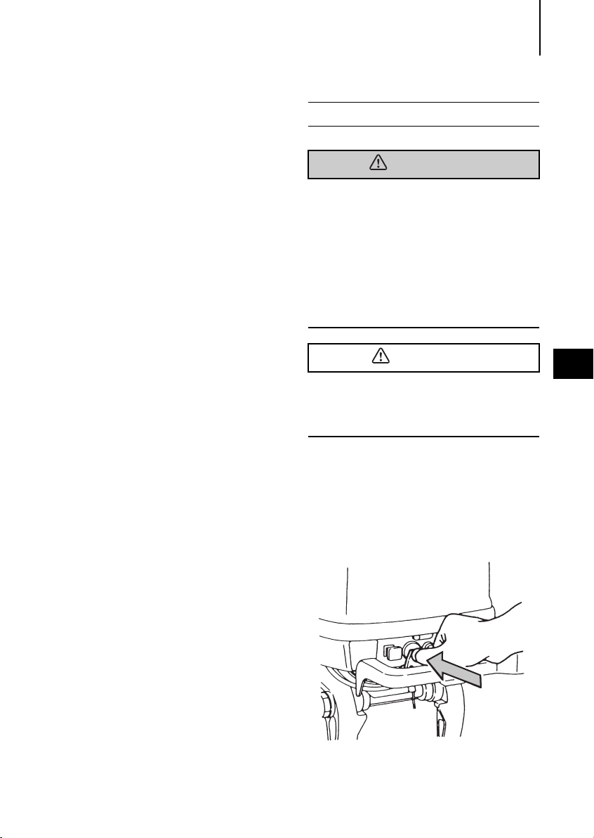
5. Stopping the engine
Do not shift into Reverse during planning,
or control will be lost leading to serious
personal injury, boat may swamp, and/or
hull may be damaged.
Do not shift into Reverse during cruis-
ing, or control may be lost, falling down
or causing passenger(s) to be thrown
overboard. Leading to serious personal
injury, and steering system and/or shifting mechanism may be damaged.
Never stop the engine immediately after a
full throttle run. Keep it running for two or
three minutes at idling speed (Shift Lever
set to Neutral) to allow it to cool down.
5
F type
1
Reduce the engine speed to idling rpm.
2
Keep pressing on the Stop Switch or
pull out the lock plate/ The engine will
then stop.
ENGINE OPERATION28
CAUTION
Air vent screw
Perpendicular to the
water surface
Notes
After stopping the engine, close the air
vent screw on the tank cap.
Disconnect the fuel connector of the
engine or the fuel tank.
Disconnect the cables from the battery if
the engine will not be used for an
extended period of time.
3
Disconnect the fuel connector from the
engine.
5
Never fill up portable fuel tanks on board to
avoid fire or explosion resulting from
spilled gasoline. If gasoline is ever spilled
on board, wipe it up thoroughly. Fuel tanks
must always be filled up on land.
4
Close the air vent screw on the fuel tank
cap.
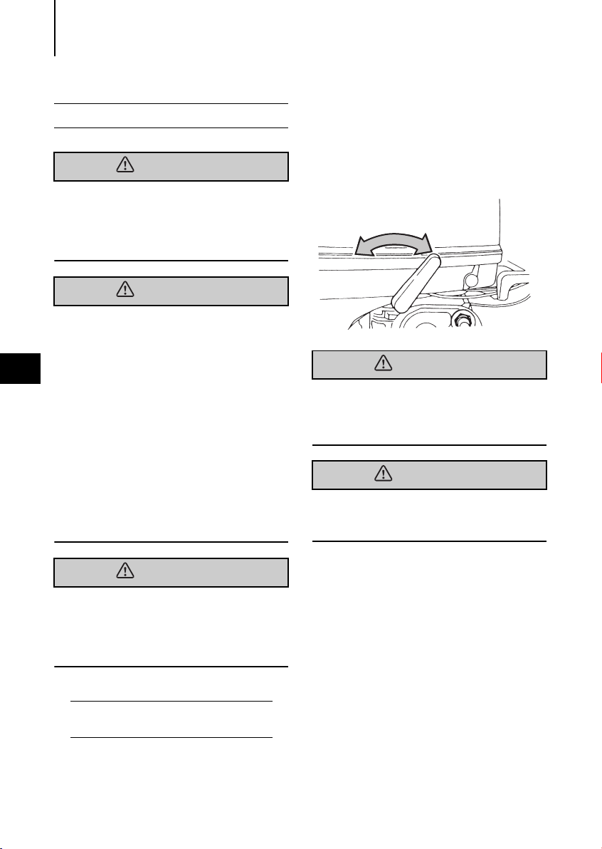
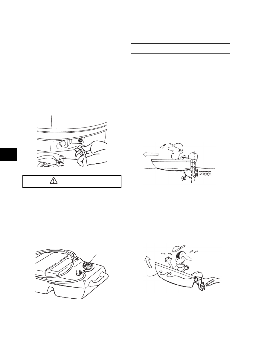
6. Trim angle
The following instructions explain how to
set the best trim angle of the boat.
F type
The trim angle is adjusted by setting the
thrust rod in the correct thrust rod hole.
Proper trim angle
The trim angle is optimum when the boat
is parallel to the water surface while running.
Improper trim angle (bow rises too
high)
If the trim angle is excessive, the bow will
rise out of the water and the speed will
decrease.
Furthermore, the bow may sway or the
bottom may slam the water while cruising.
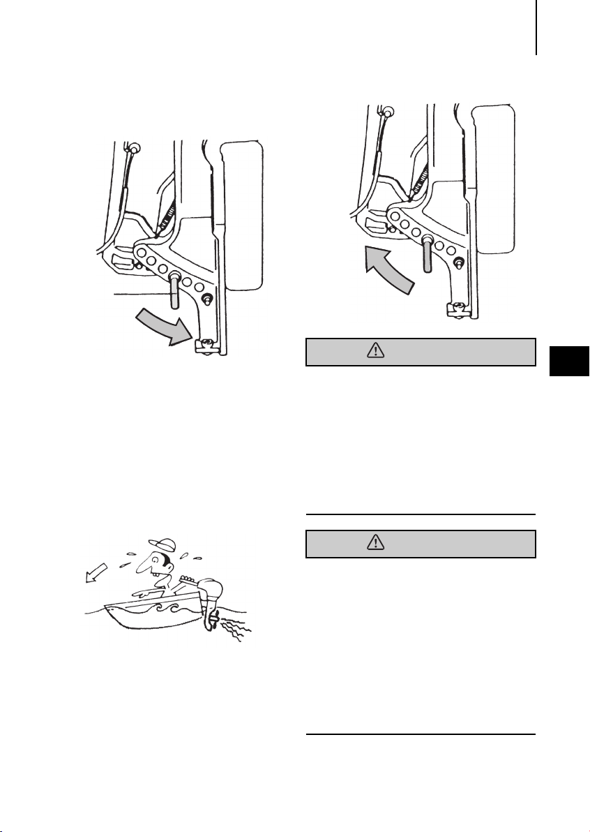
In this case, decrease the trim angle by
Select a lower hole
Thrust rod
Select a higher hole
Upward
WARNING
WARNING
setting the thrust rod in a lower hole.
ENGINE OPERATION 29
Improper Trim Angle (bow dips into
the water)
If the trim angle is too small, the bow will
dip into water, the speed will decrease,
and water may enter the boat.
In this case, the trim angle should be
increased by setting the thrust rod in a
higher hole.
Do not put hand or finger in between
5
outboard motor body and clamp bracket
when adjusting trim angle to prevent
injury in case the outboard motor body
falls.
Unsuitable trim position can cause loss
of control of boat.
When testing a trim position, run boat
slow initially to see if it can be controlled
safely.
Excessive trim up or down may lead to
unstable boat operation, potentially causing the steering difficulty that leads to accident during cruising.
Do not cruise at high speed if improper
trim position is suspected. Stop the boat
and readjust trim angle before continuing cruise.
For outboard motor model with PTT
switch on the bottom cowl, do not operate the switch during cruising, or control
of boat may be lost.
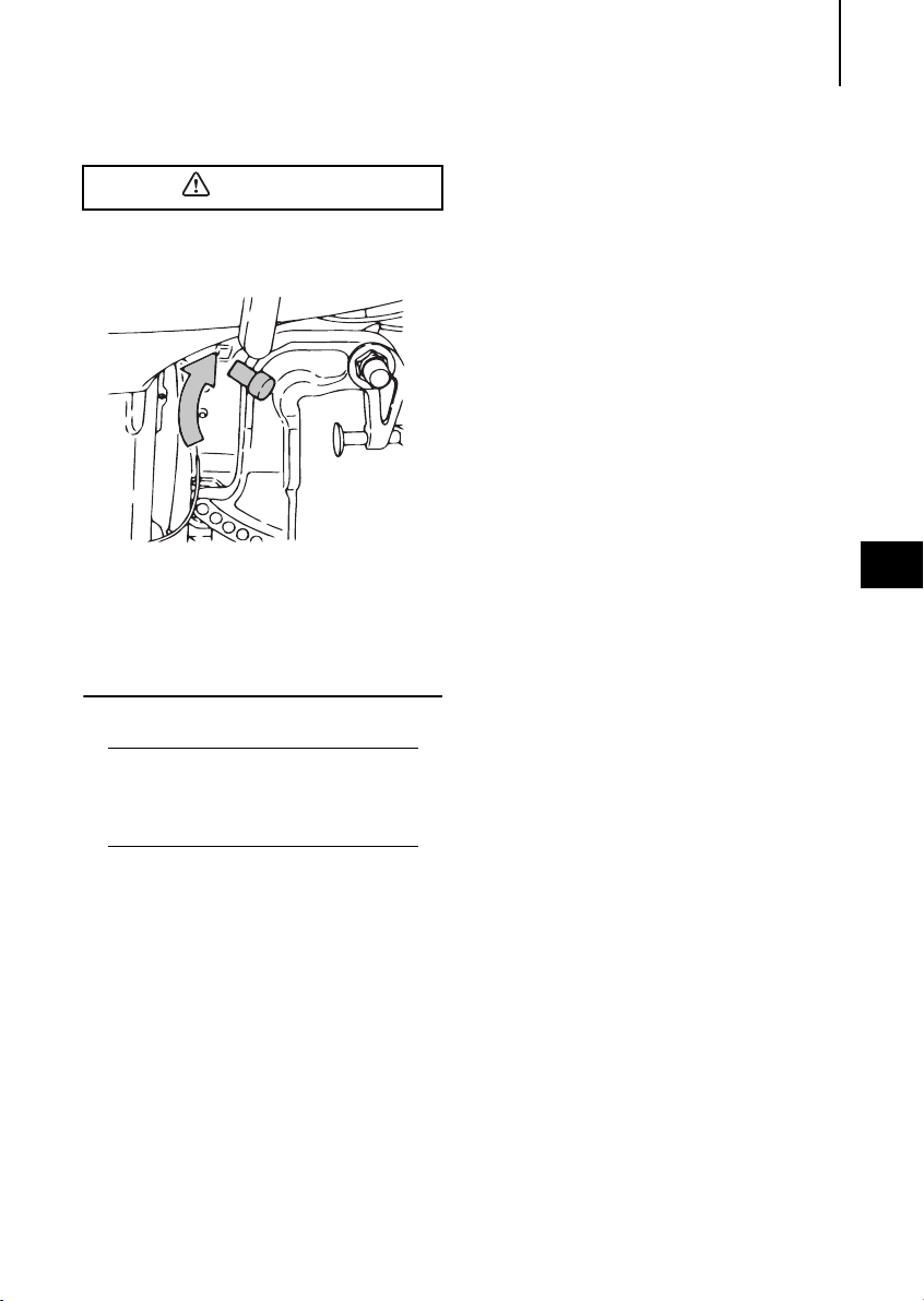
ENGINE OPERATION30
Reverse
lock lever
WARNING
CAUTION
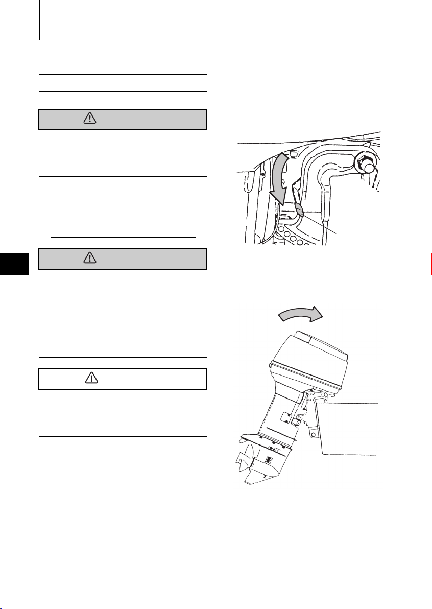
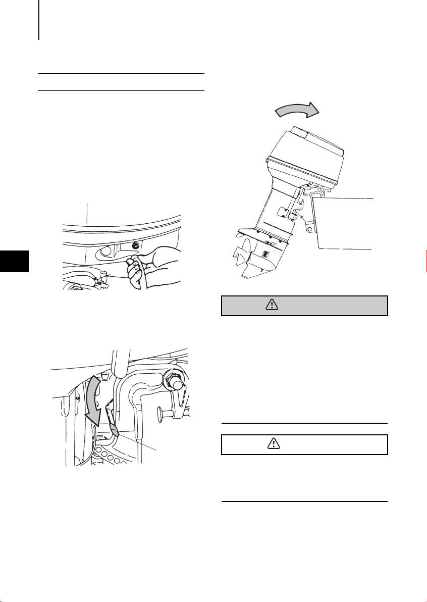
7. Mooring with the engine tilted up
When the engine has been stopped and it
will not be used for a long time or when
mooring in shallow water, tilt the engine up
to prevent damage to the propeller and
gear case.
1
Disconnect the fuel connector from the
engine.
5
2
Set the Reverse Lock Lever on the star-
board side to "RELEASE" by turning it
downward.
3
Tilt the engine up entirely. The tilt will
lock in the raised position.
Do not put hand or finger in between
outboard motor body and clamp bracket
when adjusting trim angle to prevent the
body parts from being caught in case
the outboard motor body falls.
When tilting up outboard motor with fuel
joint for over a few minutes, be sure to
disconnect fuel hose or close fuel cock,
or fuel may leak, potentially catching
fire.
Do not tilt up outboard motor during operation, or engine may be damaged from overheating because of no feed of cooling
water.
 Loading...