

TOHATSU M 40D2, M 50D2, MW 50D2 Owner's Manual
OWNER’S
MANUAL
M 40D
50D
MW 50D
OB No.003-11038-B
2
2
2

READ THIS MANUA L BEFO RE USI NG TH E OUTB OARD MOTOR. FAILUR E TO FO LLOW THE
!
INS TRUC TIO NS A ND S AFE TY P RECA UTI ONS IN THI S MA NUA L CA N RE SULT IN SER IOU S
Y OR DEATH. KEEP THIS MANUAL IN A SAFE LOCATION FOR FUTURE REFERENCE.
INJUR
Copyright © 2011 Tohatsu Corporation. All rights reserved. No part of this manual may
be reproduced or transmitted in any from or by any means without the express written
permission of Tohatsu Corporation.

YOUR TOHATSU OUTBOARD MOTOR
OWNER REGISTRATION AND IDENTIFICATION
Upon purchasing this product, be sure that the WARRANTY CARD is correctly and
completely filled out and mailed to the addressee noted there on. This WARRANTY
CARD identifies you as the legal owner of the product and serves as your warranty
registration.
TO
THE EXTENT PERMITTED BY APPLICABLE LAW, YOUR OUTBOARD MOTOR
WILL NOT BE COVERED BY THE APPLICABLE LIMITED WARRANTY, IF THIS
PROCEDURE IS NOT FOLLOWED.
PRE-DELIVERY CHECK
Be sure that the product has been checked by an authorized TOHATSU dealer before
you take delivery.
Limited Warranty
Please refer to the TOHATSU outboard motor Limited warranty provided to you with
this product, the terms and conditions of which, as amended from time to time, are
incorporated by reference into the manual.

Serial Number
In the space below, please record the outboard motor's serial number (indicated both
on the bottom cowl and on the cylinder block). The serial number will be needed in the
event of theft or to quickly identifying the outboard motor type.
Serial Number :
To You, Our Customer
Thank you for selecting a TOHATSU outboard motor. You are now the proud owner of
an excellent outboard motor that will service you for many years to come.
Th
is manual should be read in its entirety and the inspection and maintenance
procedures described later in this manual should be followed carefully. Should a
problem arise with the outboard motor, please follow the troubleshooting procedures
listed at the end of this manual. If the problem persists, contact an authorized
TOHATSU service shop or dealer.
We
hope
adventures.
you will enjoy your outboard motor and wish you good luck in your boating
TOHATSU CORPORATION

CONTENTS
GENERAL SAFETY INFORMATION
1
SPECIFICATIONS
2
NAMES OF PARTS
3
INSTALLATION
. . . . . . . . . . . . . . . . . . . . . . . . . . . . . . . . . . . . . . . . . . . . . . . . . . . .
. . . . . . . . . . . . . . . . . . . . . . . . . . . . . . . . . . . . . . . . . . . . . . . . . . .
. . . . . . . . . . . . . . . . . . . . . . . . . . . . . . . . . . . . . . . . . . . . . . . . . . . . . .
1. Mounting the outboard motor on boat
2. Propeller Selection
. . . . . . . . . . . . . . . . . . . . . . . . . . . . . . . . . . . . . . . . . . . . . . . .
3. Installing the remote control devices
4. Installing the meters
. . . . . . . . . . . . . . . . . . . . . . . . . . . . . . . . . . . . . . . . . . . . . . .
5. Installing the drag link assembly
6. Installing the battery
4
PRE-OPERATING PREPARATIONS
. . . . . . . . . . . . . . . . . . . . . . . . . . . . . . . . . . . . . . . . . . . . . . .
1. Recommended gasoline types
2. Recommended engine oil
3. Break-in
4. Warning system
5
ENGINE OPERATION
1. Starting
. . . . . . . . . . . . . . . . . . . . . . . . . . . . . . . . . . . . . . . . . . . . . . . . . . . . . . . . . .
. . . . . . . . . . . . . . . . . . . . . . . . . . . . . . . . . . . . . . . . . . . . . . . . . . .
. . . . . . . . . . . . . . . . . . . . . . . . . . . . . . . . . . . . . . . . . . . . . . . . . . . . . . . . . .
2. Warming up the engine
3. Forward and reverse
4. Shallow water running
5. Stopping the engine
6. Trim angle
. . . . . . . . . . . . . . . . . . . . . . . . . . . . . . . . . . . . . . . . . . . . . . . . . . . . . . . .
. . . . . . . . . . . . . . . . . . . . . . . . . . . . . . . . . . . . . . . . . .
. . . . . . . . . . . . . . . . . . . . . . . . . . . . . . . . . . . . . . . . . . . . . . . .
. . . . . . . . . . . . . . . . . . . . . . . . . . . . . . . . . . . . . . . . . . . .
. . . . . . . . . . . . . . . . . . . . . . . . . . . . . . . . . . . . . . . . . . . . . . .
. . . . . . . . . . . . . . . . . . . . . . . . . . . . . . . . . . . . . . . . . . . . .
. . . . . . . . . . . . . . . . . . . . . . . . . . . . . . . . . . . . . . . . . . . . . . .
7. Mooring with the engine tilted up
6
REMOVING AND CARRYING THE OUTBOARD MOTOR
1. Removing the outboard motor
2. Carrying the outboard motor
3. Storing the outboard motor
7
TRAILERING
8
ADJUSTMENT
. . . . . . . . . . . . . . . . . . . . . . . . . . . . . . . . . . . . . . . . . . . . . . . . . . . . . . . .
. . . . . . . . . . . . . . . . . . . . . . . . . . . . . . . . . . . . . . . . . . . . . . . . . . . . . . .
1. Remote control lever load
2. Trim tab adjustment
3. Steering load adjustment
. . . . . . . . . . . . . . . . . . . . . . . . . . . . . . . . . . . . . . . . . . . . . . .
. . . . . . . . . . . . . . . . . . . . . . . . . . . . . . . . . . . . . . . . . . .
4. Throttle grip turning load adjustment
9
INSPECTION AND MAINTENANCE
1. Daily inspection
2. Periodic inspection
3. Off-season storage
4. Pre-season check
. . . . . . . . . . . . . . . . . . . . . . . . . . . . . . . . . . . . . . . . . . . . . . . . . . .
. . . . . . . . . . . . . . . . . . . . . . . . . . . . . . . . . . . . . . . . . . . . . . . .
. . . . . . . . . . . . . . . . . . . . . . . . . . . . . . . . . . . . . . . . . . . . . . . .
. . . . . . . . . . . . . . . . . . . . . . . . . . . . . . . . . . . . . . . . . . . . . . . . .
5. Checking after striking underwater object
6. If the engine becomes submerged in water
7. Precautions in cold weather
. . . . . . . . . . . . . . . . . . . . . . . . . . . . . . . . . . . .
. . . . . . . . . . . . . . . . . . . . . . . . . . . . . . .
. . . . . . . . . . . . . . . . . . . . . . . . . . . . . . . . .
. . . . . . . . . . . . . . . . . . . . . . . . . . . . . . . . . . . .
. . . . . . . . . . . . . . . . . . . . . . . . . . . . . . . . . . .
. . . . . . . . . . . . . . . . . . . . . . . . . . . . . . . . . . . . . .
. . . . . . . . . . . . . . . . . . . . . . . . . . . . . . . . . . . .
. . . . . . . . . . . . . . . . . . . . . . . . . . . . . . . . . . . . .
. . . . . . . . . . . . . . . . . . . . . . . . . . . . . . . . . . . . . . .
. . . . . . . . . . . . . . . . . . . . . . . . . . . . . . . . . . . . . . . . .
. . . . . . . . . . . . . . . . . . . . . . . . . . . . . . . . . . . . . . . . . .
. . . . . . . . . . . . . . . . . . . . . . . . . . . . . . . .
. . . . . . . . . . . . . . . . . . . . . . . . . . . . . . . . . . .
. . . . . . . . . . . . . . . . . . . . . . . . . . . .
. . . . . . . . . . . . . . . . . . . . . . . . . . .
. . . . . . . . . . . . . . . . . . . . . . . . . . . . . . . . . . . . . . . .
. . . . . . . . . . . . . . . .
8
10
13
20
20
23
23
26
28
29
31
31
33
36
37
38
38
46
47
50
51
53
56
59
59
59
61
62
63
63
63
64
64
65
66
70
75
76
77
78
78

10
TROUBLESHOOTING
11
TOOL KIT AND SPARE PARTS
12
OPTIONAL ACCESSORIES
13
PROPELLER TABLE
. . . . . . . . . . . . . . . . . . . . . . . . . . . . . . . . . . . . . . . . . . . . . . . .
. . . . . . . . . . . . . . . . . . . . . . . . . . . . . . . . . . . . . . . . . . . . . . . . .
. . . . . . . . . . . . . . . . . . . . . . . . . . . . . . . . . . . . . . .
. . . . . . . . . . . . . . . . . . . . . . . . . . . . . . . . . . . . . . . . . . .
79
81
82
84
INDEX
GENERAL SAFETY INFORMATION
7
1. SPECIFICATIONS
2. NAMES OF PARTS
3. INSTALLATION
4.PRE-OPERATING PREPARATIONS
5.ENGINE OPERATION
REMOVING AND CARRYING THE OUTBOARD MOTOR
6.
7.TRAILERING
8.ADJUSTMENT
9.INSPECTION AND MAINTENANCE
1
1
2
2
3
3
4
4
5
5
6
6
7
7
8
8
9
9
10.TROUBLESHOOTING
11.TOOL KIT AND SPARE PARTS
12.OPTIONAL ACCESSORIES
13.PROPELLER TABLE
10
10
11
11
12
12
13
13
!
!
!
!
8
GENERAL SAFETY INFORMATION
NOTICE : DANGER/WARNING/CAUTION/Note
Before installing, operating or otherwise handling your outboard motor, be sure
to thoroughly read and understand this Owner's Manual and carefully follow all of
the instructions. Of particular importance is information preceded by the words
"DANGER," "WARNING," "CAUTION," and "Note." Always pay special attention to
such information to ensure safe operation of the outboard motor at all times.
Failure to observe will result in severe personal injury or death, and possibly property damage.
Failure to observe could result in severe personal injury or death, or property damage.
Failure to observe could result in personal injury or property damage.
Note
This instruction provides special information to facilitate the use or maintenance of the
outboard motor or to clarify important points.
EMERGENCY STOP SWITCH
The Emergency Stop Switch will stall the outboard motor when the stop switch tether
is pulled off. This stop switch tether can be attached to the operator of the outboard
motor to minimize or prevent injuries from the propeller in case the operator falls
overboard.
We highly recommend use of the Emergency Stop Switch tether.
Accidental activation of the Emergency Stop Switch (such as the tether being pulled out
in heavy seas) could cause passengers to lose their balance and even fall overboard,
or it could result in loss of power in heavy seas, strong currents, or high winds. Loss of
control while mooring is another potential hazard.
To minimize accidental activation of the Emergency Stop Switch, the 500 mm (20 inch.)
stop switch tether is coiled and can extended to a full 1,300 mm (51 inch.).
!
SAFE OPERATION OF BOAT
As the operator/driver of the boat, you are responsible for the safety of those aboard
and those in other boat around yours, and for following local boating regulations. You
should be thoroughly knowledgeable on how to correctly operate the boat, outboard
motor, and accessories. To learn about the correct operation and maintenance of the
outboard motor, please read through this manual carefully.
I
t
is very difficult for a person standing or floating in the water to take evasive action
should he or she see a power boat heading in his /her direction, even at a slow speed.
Therefore, when your boat is in the immediate vicinity of people in the water, the
outboard motor should be shifted to neutral and shut off.
SERIOUS INJURY IS LIKELY IF A PERSON IN THE WATER MAKES CONTACT WITH
A MOVING BOAT, GEAR HOUSING, PROPELLER, OR ANY SOLID DEVICE RIGIDLY
ATTACHED TO A BOAT OR GEAR HOUSING.
SERVICING, REPLACEMENT PARTS & LUBRICANTS
We recommend that only an authorized service shop perform service or maintenance
on this outboard motor. Be sure to use genuine parts, genuine lubricants, or
recommended lubricants.
9
MAINTENANCE
As the owner of this outboard motor, you should be acquainted with correct
maintenance procedures. It is the operator's responsibility to perform all safety checks
and to ensure that all lubrication and maintenance instructions are complied with
for safe operation. Please comply with all instructions concerning lubrication and
maintenance. You should take the engine to an authorized dealer or service shop for
periodic inspection at the prescribed intervals.
Correct
chance of problems and limit overall operating expenses.
MOUNTING
Outboard motor mounting must be performed by trained service person(s) using lift or
hoist with sufficient capacity.
periodic
maintenance and proper care of this outboard motor will reduce the

1
10
SPECIFICATIONS
40D2 50D2 MF, EF, EFO
MODEL 40D2 50D2
Item MF EF EFO
Overall Length mm (in) 1,143 (45.0)
Overall Width mm (in) 384 (15.1)
Overall Height S·L·UL mm (in) 1,225 (48.2) · 1.352 (53.2) · 1,479 (58.2)
Transom Height S·L·UL mm (in) 403 (15.9) · 530 (20.9) · 657 (25.9)
S kg (lb) 72 (159) - -
Weight
Output kW (Hp) 40D2 : 29.4 (40), 50D2 : 36.8 (50)
Max. Operating Range rpm 40D2 : 5,000-5,700, 50D2 : 5,150-5,850
Number of Cylinders 3
Piston Displacement
Bore x Stroke mm (in) 68
Exhaust System Through hub exhaust
Engine Lubrication Premixed Fuel Auto mixing
Fuel mixing Ratio 50 : 1 120 : 1-50 : 1
Cooling System Forced water cooling
Starting System Manual Electric starter motor
Ignition System Flywheel Magneto C.D. Ignition
Spark Plugs
Alternator 12V, 130W (12V, 11A)
Trim Position 6
Engine Oil Genuine Motor Oil or recommended one (TCW-III)
Gear Oil
Fuel Tank Capacity L (US gal) 25 (6.6)
Engine Oil Capacity L (US gal) - Approx. 2.0 (0.53)
Gear Reduction Ratio 1.85 (13 : 24)
Fuel
Remark: This specifications might change without a previous notice.
L kg (lb) 73.5 (162) 78.5 (173) 80 (176)
UL kg (lb) 75 (165) - 81.5 (180)
mL (Cu in) 697 (42.53)
× 64 (2.68 × 2.52)
40D2 : NGK B7HS-10/BR7HS-10
50D2 : NGK B8HS-10/BR8HS-10
Genuine Gear Oil or API GL5,
SAE #80 to #90, approx. 500mL
Unleaded regular gasoline pump posted 87 Octane
(research octane rating of 91)

SPECIFICATIONS
40D2 50D2 EFTO, EPO, EPTO
MODEL 40D2 50D2
Item EFTO EPO EPTO
Overall Length mm (in) 1,143 (45.0) 630 (24.8)
Overall Width mm (in) 384 (15.1) 340 (13.4) 355 (14.0)
Overall Height S·L·UL mm (in)
Transom Height S·L·UL mm (in) 403 (15.9) · 530 (20.9) · 657 (25.9)
S kg (lb) 87.5 (193) 74.5 (164) 83.5 (184)
Weight
Output kW (Hp) 40D2 : 29.4 (40), 50D2 : 36.8 (50)
Max. Operating Range rpm 40D2 : 5,000-5,700, 50D2 : 5,150-5,850
Number of Cylinders 3
Piston Displacement
Bore x Stroke mm (in) 68
Exhaust System Through hub exhaust
Engine Lubrication Auto mixing
Fuel mixing Ratio 120 : 1-50 : 1
Cooling System Forced water cooling
Starting System Electric starter motor
Ignition System Flywheel Magneto C.D. Ignition
Spark Plugs
Alternator 12V, 130W (12V, 11A)
Trim Position 4 6 4
Engine Oil Genuine Motor Oil or recommended one (TCW-III)
Gear Oil
Fuel Tank Capacity L (US gal) 25 (6.6)
Engine Oil Capacity L (US gal) Approx. 2.0 (0.53)
Gear Reduction Ratio 1.85 (13 : 24)
Fuel
Remark: This specifications might change without a previous notice.
L kg (lb) 89 (196) 76 (168) 85 (187)
UL kg (lb) 90.5 (200) 77.5 (171) 86.5 (191)
mL (Cu in) 697 (42.53)
1,225 (48.2) · 1.352 (53.2)
1,479 (58.2)
Unleaded regular gasoline pump posted 87 Octane
1,212 (47.7) · 1,339 (52.7) · 1,466 (57.7)
× 64 (2.68 × 2.52)
40D2 : NGK B7HS-10/BR7HS-10
50D2 : NGK B8HS-10/BR8HS-10
Genuine Gear Oil or API GL5,
SAE #80 to #90, approx. 500mL
(research octane rating of 91)
11
1

1
SPECIFICATIONS
12
W50D2 MF, EPT, EPO
MODEL 50D2
Item MF EPT EPO
Overall Length mm (in) 1,145 (45.1) 630 (24.8)
Overall Width mm (in) 384 (15.1) 355 (14.0) 340 (13.4)
Overall Height L mm (in) 1,413 (55.6) 1,410 (55.1)
Transom Height L mm (in) 550 (21.7)
Weight L
Output kW (Hp) 36.8 (50)
Max. Operating Range rpm 5,150-5,850
Number of Cylinders 3
Piston Displacement
Bore x Stroke mm (in) 68
Exhaust System Through hub exhaust
Engine Lubrication Premixed Fuel Auto mixing
Fuel mixing Ratio 50 : 1 120 : 1–50 : 1
Cooling System Forced water cooling
Starting System Manual Electric starter motor
Ignition System Flywheel Magneto C.D. Ignition
Spark Plugs NGK B8HS-10/BR8HS-10
Alternator 12V, 130W (12V, 11A)
Trim Position 6 4 6
Engine Oil Genuine Motor Oil or recommended one (TCW-III)
Gear Oil
Fuel Tank Capacity L (US gal) 25 (6.6)
Engine Oil Capacity L (US gal) - Approx. 2.0 (0.53)
Gear Reduction Ratio 1.92 (12 : 23)
Fuel
Remark: This specifications might change without a previous notice.
kg (lb) 79 (174) 84 (185) 81.5 (180)
mL (Cu in) 697 (42.53)
× 64 (2.68 × 2.52)
Genuine Gear Oil or API GL5,
SAE #80 to #90, approx. 700mL
Unleaded regular gasoline pump posted 87 Octane
(research octane rating of 91)
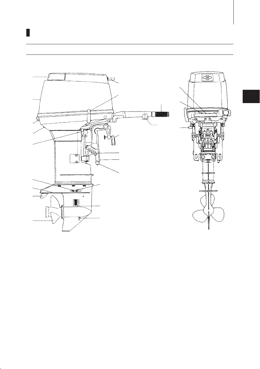
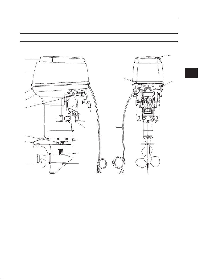
NAMES OF PARTS
1
2
3
4
5
6
7
8
9
i
u
w
q
0
o
p
a
5
t
r
e
s
y
40D2MF/W50D2MF
13
2
1
Tilt Handle
2
Top Cowl
3
Hook Lever
4
Water Check Port
5
Reverse Lock Lever
6
Water Plug
7
Anti-ventilation Plate
8
Trim Tab
9
Propeller
0
Oil Plug (lower)
q
Water Strainer
w
Oil Plug (upper)
e
Clamp Bracket
r
Thrust Rod
t
Clamp Screw
y
Throttle Grip
u
Adjust Nut
i
Shift Lever
o
Starter Handle
p
Stop Switch
a
Choke Knob
s
Anode
2
1
2
3
4
5
6
7
8
9
t
i
u
w
d
f
e
r
q
0
o
p
5
y
s
a
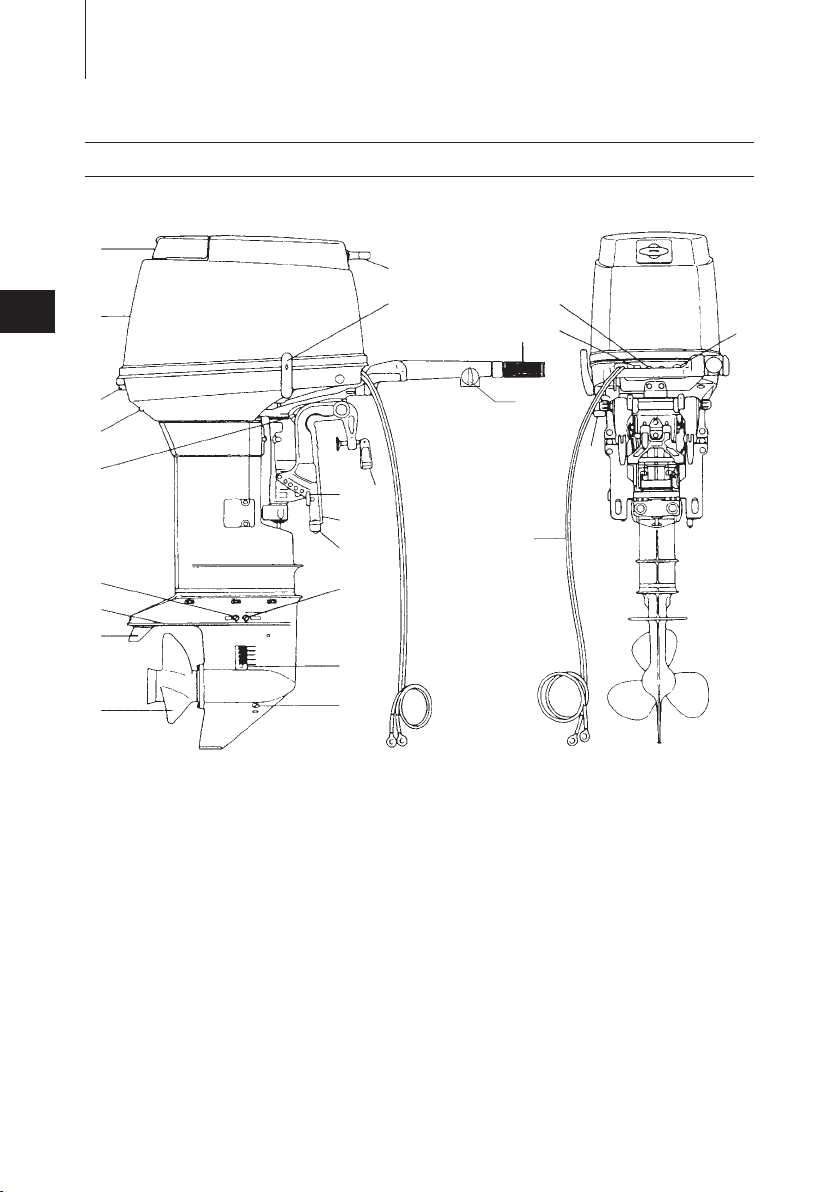
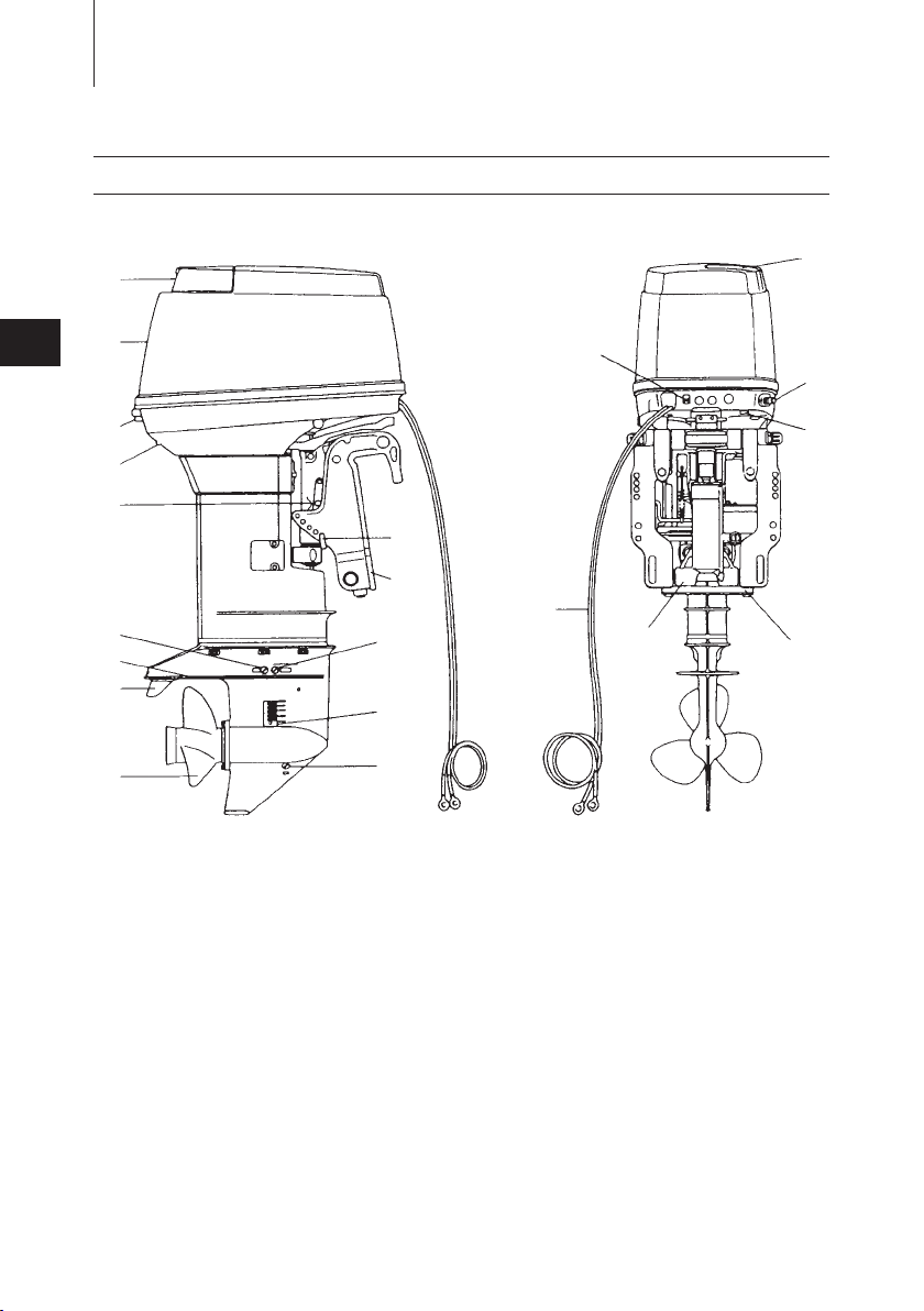
NAMES OF PARTS
14
40D2EF/50D2EF
1
Tilt Handle
2
Top Cowl
3
Hook Lever
4
Water Check Port
5
Reverse Lock Lever
6
Water Plug
7
Anti-ventilation Plate
8
Trim Tab
9
Propeller
0
Oil Plug (lower)
q
Water Strainer
w
Oil Plug (upper)
e
Clamp Bracket
r
Thrust Rod
t
Clamp Screw
y
Throttle Grip
u
Adjust Nut
i
Shift Lever
o
Starter Handle
p
Stop Switch
a
Choke Knob
s
Main Switch
d
Battery Cords
f
Anode
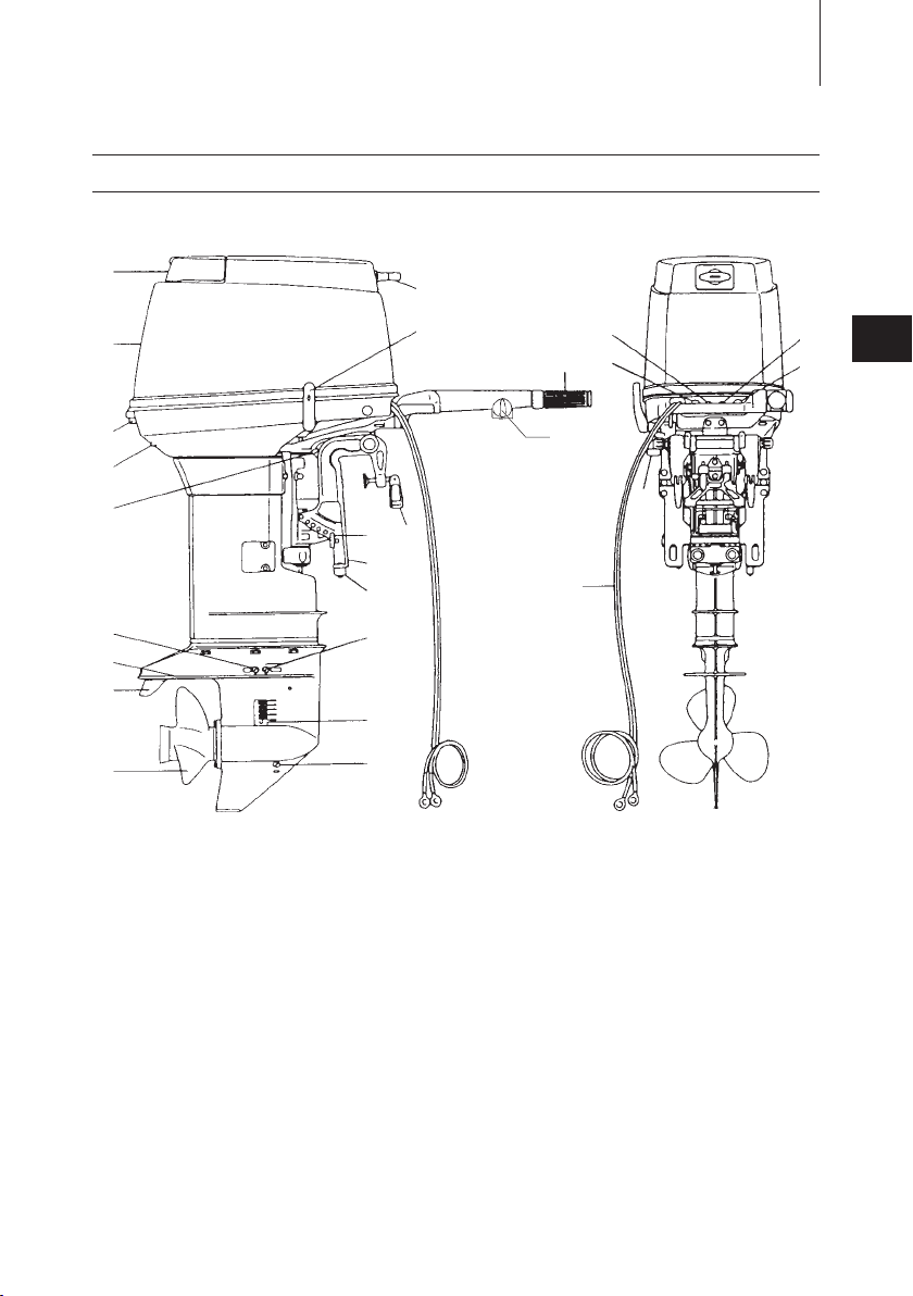
40D2EFO/50D2EFO
t
w
a
e
r
q
0
1
2
3
4
5
6
7
8
9
5
f
g
i
u
o
p
y
d
s
NAMES OF PARTS
15
2
1
Tilt Handle
2
Top Cowl
3
Hook Lever
4
Water Check Port
5
Reverse Lock Lever
6
Water Plug
7
Anti-ventilation Plate
8
Trim Tab
9
Propeller
0
Oil Plug (lower)
q
Water Strainer
w
Oil Plug (upper)
e
Clamp Bracket
r
Thrust Rod
t
Clamp Screw
y
Throttle Grip
u
Adjust Nut
i
Shift Lever
o
p
a
s
d
f
g
Starter Handle
Stop Switch
Choke Knob
Anode
Pilot Lamp
Main Switch
Battery Cords
2
t
w
e
r
q
0
1
2
3
4
5
6
7
8
9
○
5
i
u
y
o
p
a
s
h
g
f
d
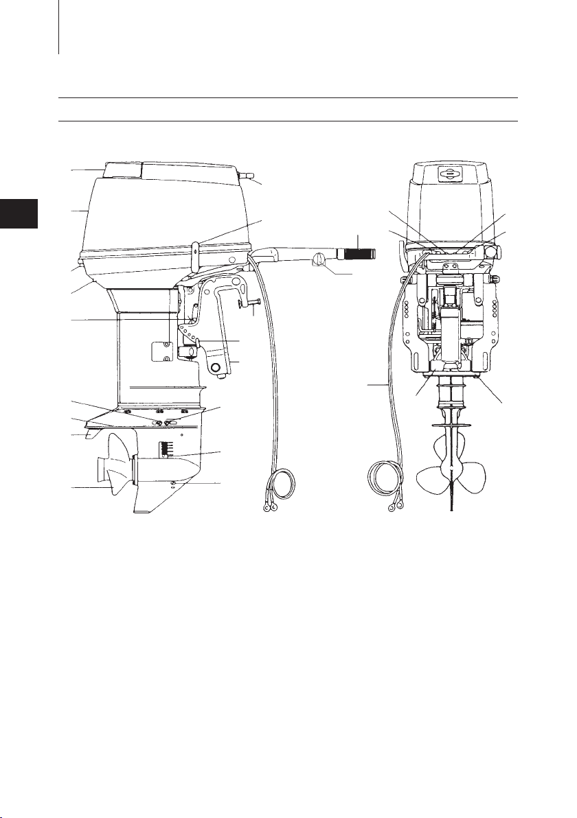
NAMES OF PARTS
16
40D2EFTO/50D2EFTO
1
Tilt Handle
2
Top Cowl
3
Hook Lever
4
Water Check Port
5
Reverse Lock Lever
6
Water Plug
7
Anti-ventilation Plate
8
Trim Tab
9
Propeller
0
Oil Plug (lower)
q
Water Strainer
w
Oil Plug (upper)
e
Clamp Bracket
r
Thrust Rod
t
Clamp Screw
y
Throttle Grip
u
Adjust Nut
i
Shift Lever
o
Starter Handle
p
Stop Switch
a
Choke Knob
s
Pilot Lamp
d
Main Switch
f
Battery Cords
g
Power Trim & Tilt
h
Anode
NAMES OF PARTS
t
w
p
e
r
q
0
1
2
3
4
5
6
7
8
9
○
5
y
o
u
i
17
40D2EPO/50D2EPO
2
1
Tilt Handle
2
Top Cowl
3
Hook Lever
4
Water Check Port
5
Reverse Lock Lever
6
Water Plug
7
Anti-ventilation Plate
8
Trim Tab
9
Propeller
0
Oil Plug (lower)
q
Water Strainer
w
Oil Plug (upper)
e
Clamp Bracket
r
Thrust Rod
t
Clamp Screw
y
Choke Knob
u
Filler Lid
i
Fuel Connecter
o
p
Battery Cords
Anode
NAMES OF PARTS
w
e
r
q
0
1
2
3
4
5
6
7
8
9
○
5
t
o
y
u
i
p
a
18
40D2EPTO/50D2EPTO
2
1
Tilt Handle
2
Top Cowl
3
Hook Lever
4
Water Check Port
5
Reverse Lock Lever
6
Water Plug
7
Anti-ventilation Plate
8
Trim Tab
9
Propeller
0
Oil Plug (lower)
q
Water Strainer
w
Oil Plug (upper)
e
Clamp Bracket
r
Thrust Rod
t
Choke Knob
y
Filler Lid
u
Fuel Connecter
i
Power Trim & Tilt Switch
o
Battery Cords
p
Power Trim & Tilt
a
Anode
NAMES OF PARTS
for P Type for P Type
for T Type
1
3
2
4
5
7
6
q
0
9
8
w
e
19
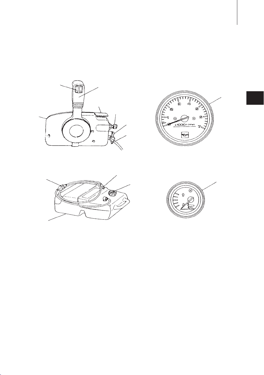
2
1
Remote Control Box
2
Remote Control Lever
3
Power Trim & Tilt Switch
4
Neutral Warm-up Lever
5
Main Switch
6
Harness B
7
Stop Switch
8
Fuel tank
9
Air Vent Screw
0
Fuel Connector
q
Primer Bulb
w
Tachometer
e
Trim meter
3
!
!
A A
470 - 660 mm
(18.5 - 26.1 in)
20
INSTALLATION
1.
Mounting the outboard motor on boat
Most boats are rated and certified
in terms of their maximum allowable
horsepower, as shown on the boat’
s certification plate. Do not equip your
boat with an outboard motor that
exceeds this limit. If in doubt, contact
your dealer.
Do not operate the outboard motor until
it has been securely mounted on the
boat in accordance with the instructions
below.
Note
Consult your authorized dealer to
receive the proper instructions or ask
your dealer to mount the motor as
necessary.
Installation
Single-engine Installation
■
sition the outboard engine at the
Po
exact center of the stern, and mount it
using a cushioning pad or plate.
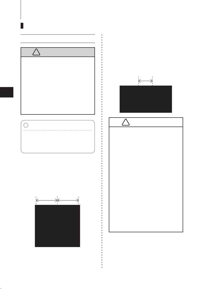
Twin-engine Installation
■
W
h
e n i n s t a l l i n g t w o o u tb o a r d
engines, be sure to keep an interval of
approximately 470 - 660 mm (18.5 - 26
in) between the two.
Before beginning the running test,
●
check that the boat with maximum
capacity loading floats on the
water in a proper attitude. Check
the position of water surface on
the driveshaft housing. If the water
surface is near the bottom cowling,
in high waves, water may enter the
engine cylinders.
Incorrect outboard motor mounting
●
height or existence of under water
object (s), such as hull bottom
design, bottom surface conditions
or underwater accessories,
can cause water spray possibly
reaching the engine through an
opening of the bottom cowling
during cruising. Exposing engine
to such conditions for extended
periods can lead to severe engine
damage.
INSTALLATION
Anti-ventilation Plate
10~30mm (0.4~1.2 in.)
!
!
21
Transom Height
■
stall the engine with the Anti-ventilation
In
Plate at a level 10~30mm(0.4~1.2in.)
below the bottom of the boat.
Transom Matching
■
Be
sure
that anti ventilation plate of the
outboard is below the water surface
when running with wide open throttle.
I
n case the above condition cannot
be met due to the shape of your boat,
please consult your authorized dealer.
Overheating may occur if the Antiventilation Plate is at a level higher
than the bottom of the boat, as a result
of a lack of cooling water.
I
f th e he i gh t di f fe r e n c e ex c ee d s
10~30mm (0.4~1.2 in) engine power
performance is likely to be reduced as
a result of increased water resistance
to the gear case assembly.
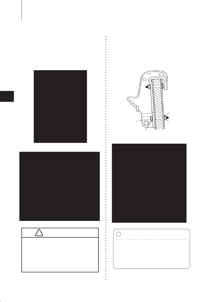
Attaching the Clamp Bracket
■
Af
er positioning the Clamp Bracket, fix it
t
with clamp screw then drill four holes in
the transom board, matching the holes
in the Clamp Bracket. Secure the engine
with the supplied bolts (M12×105mm)
and nuts. Be sure to use the washers.
Use the larger diameter washers inside
of the transom board and use the small
diameter washers outside of the clamp
bracket.
The mounting hole s may be dr illed
b e f o r eh a n d by re f e r r i n g t o th e
dimensional drawing.
Mounting the outboard motor
●
without following this manual can
lead to unsafe conditions such as
poor maneuverability, going out of
control or fire disaster.
Loose clamp screws and/or
●
mounting bolts can lead to the
release or displacement of the
outboard motor, possibly resulting
in lost of control and/or serious
personal injury. Be sure that
fasteners are tightened to the
specified torque (30 Nm (3.0kgf)
13ft·lb). Check the fasteners for
tightness from time to time.
Be sure to use outboard mounting
●
fasteners included in the outboard
motor package or their equivalents
in terms of size, material, quality and
strength.
Tighten fasteners to the specified
torque (30 Nm (3.0kgf) 13ft·lb). Test
cruise to check if fasteners are
tightened securely.
Outboard motor mounting must
●
be performed by trained service
person(s) using lift or hoist with
sufficient capacity.
3
INSTALLATION
Nut
Bolt
(12mm ×length 105mm)
Washer
(large diameter)
Washer
(small diameter)
ø13
ø13
234(9.21”)
39(1.54”)
222(8.74”)
248(9.76”)
26(1.02”
)
204(8.03”)
25(0.98”)
25(0.98”)
64(2.52”)
89(3.50”)
117(4.61”)
102(4.02”)102(4.02”)
117(4.61”)
Top of transom
Nut
Washer
(small
diameter)
Washer
(large
diameter)
Bolt (12mm ×length 105mm)
251
ø12.5
ø12.5
253.5
(
2.0”
)
(
10.0”
)
56
(
2.2”
)
181818
51
327
(
12.9”
)
(
9.9”
)
!
22
Clamp Bracket
Dimensional Drawing
3
Manual tilting type
■
F, EF, EFO, EPO
with the Power Trim and Tilt type
■
EFTO, EPTO
Mounting bolts should be installed with
the bolt head at inside surface of the
transom. Mounting bolts installed with
the threaded end at the inside surface
of the transom can cause personal
injury.
Notes
1. Apply sealing agent such as silicon
sealer between bolts and transom
board holes before tightening bolts.
2. Be sure to tighten mounting bolt
nuts to specified torque.
INSTALLATION
!
23
2. Propeller Selection 3.
A propeller must be selected so that
the engine rpm measured at wide open
throttle while cruising is within the max.
operating range;
40D2 : 5,000 to 5,700 rpm
50D2 : 5,150 to 5,850 rpm
Fo r ge nu i n e p ro p e l l e r s, re f er to
Propeller Table of this manual.
Installing the remote control devices
When using other than Tohatsu’s genuine
remote control box, DO NOT select the
one without neutral safety switch that
prevents in-gear start.
Use of remote control box without neutral
safety switch can allow start of engine with
gear at other than neutral shift, potentially
leading passengers to falling or causing
passenger to be thrown overboard.
I
t
is recommended that you consult
wi t h yo u r au t h o r i z e d de a l er fo r
installation adjustment of the remote
control device.
I
nstallation of the Remote Control
■
Cables (Box side) :
Fo
llow the instruction manual provided
with the remote control box.
nstallation of the Remote Control
I
■
Box on your boat :
Fo
llow the instruction manual provided
with the remote control box.
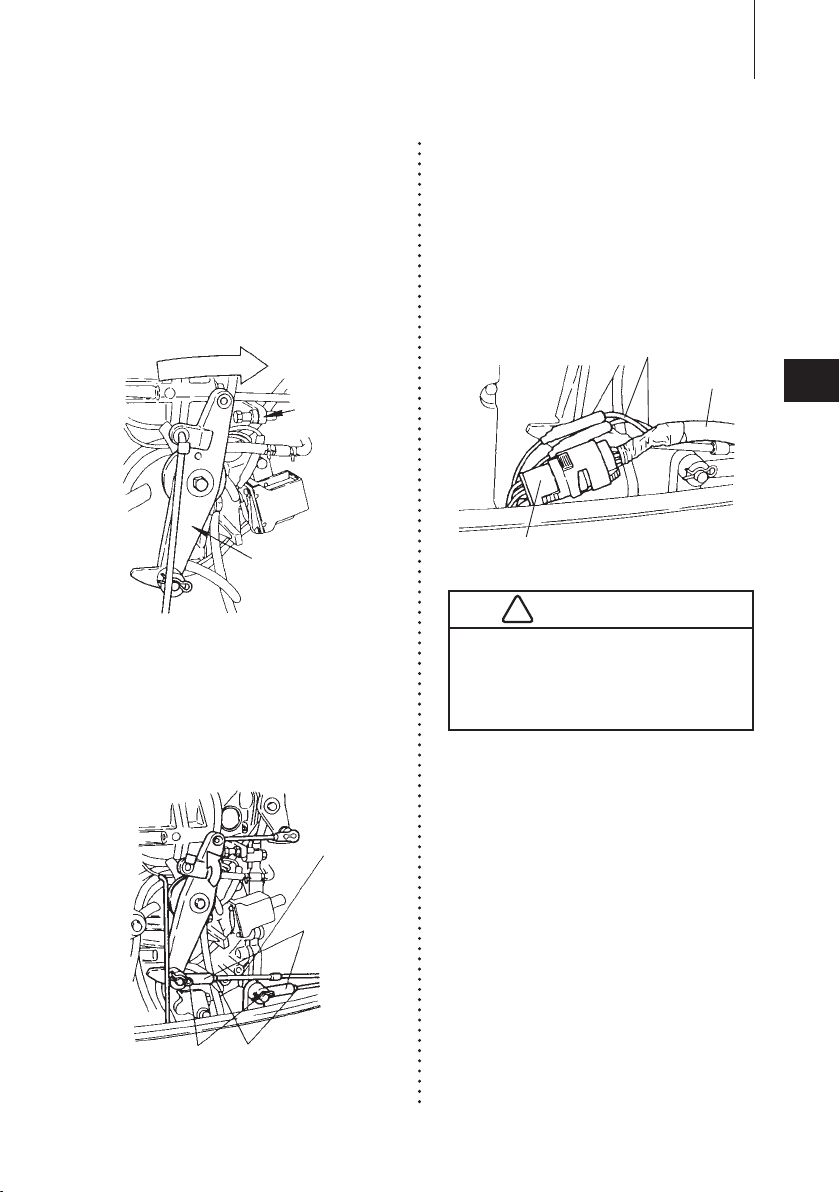
3
onnecting the Rem ote Control
C
■
Cable to the engine :
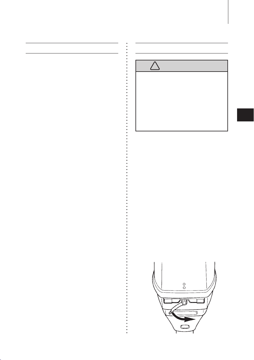
1
D
tach the top cowl by turning the
e
lever.
INSTALLATION
Bracket
Screw
Throttle Cable
Shift Cable
Grommet
Clutch
Cable
Throttle
Cable
Meter
lead wire
Co
rd
Ass’ y B
Battery Cord
Throttle
Cable
Joint
R shaped
pin
Shift Cable Joint
Washer
Washer
R shaped
pin
!
Cable joint
Lock nut
Remote control cable
Approx. 10 mm (0.39 inch)
Free Accel
lever
Fully opened
Fully
closed
Approx. 32°
24
3
2
Detach the bracket and set Cable
Ha rness B and Remo te Con trol
Cables.
aving fixed the Remote Control
H
Cables to the bracket, tie them to
the bottom cowl.
Be careful not to loop the remote
control cables to a diameter of 406
mm (16 inches) or less.
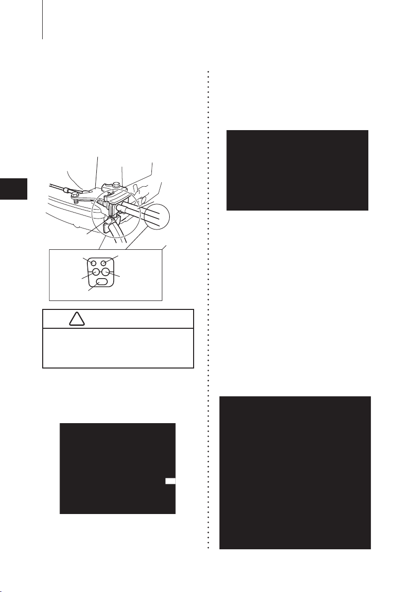
3
D
tach the throttle and shift cable
e
joints by removing the R-shaped
pins.
Thread at least 15mm (0.59 in.) of
●
t
he remote Control Cables through
the terminal eyes. Securely lock the
terminal eyes with lock nuts.
4
M
o
ve the Rem ote C ontrol lever
Forward, to Neutral and to Reverse
to confirm the shift is working, and
then set the lever no Neutral.
D
ouble-check that the Remote Control
●
ables, the throttle cable
C
cable have been
connected correctly.
and shift
Move the Re mote Control Lever
Forward until the first engaging point
(approx 32˚). The cabl e which is
moved first when the lever is turned
is a shift cable. Check that the shift
le ver is in Neut ral a nd the Fre e
INSTALLATION
Advancer arm
Stopper
(Throttle fully
closed side)
Throttle
Cable
Cable Joint
R shaped pin Nut
Cable
Harness A
Lead wire
Cable
Harness B
!
25
Accel lever is fully closed when the
remote control cables have been
connected.
The advancer arm on the engine should
●
h
ave contact with the stopper of the
carburetor throttle valve to enable it to
be fully closed.
5
A
ju st cab le joi nt unt il th e hole
d
mee t s with th e Advan c e r Arm
pin. After adjustment lock a cable
joint with a nut and secure with
R-shaped pin.
Connecting Cords and cable
1
C
nnect cable harness B to cable
o
harness A.
2
Connect pink and light blue leads
from cable harness A and B to each
other.
Do not disconnect the electric
couplers while the engine is running,
as this will damage the C.D. unit and
could result in a serious electric shock.
3
3
12P
6P
4P
Selector
ø85
Tachometer
ø52.5
Trim meter
Fitting plate
Fitting plate
Dash
board
50° - 70°
Dash
board
INSTALLATION
26
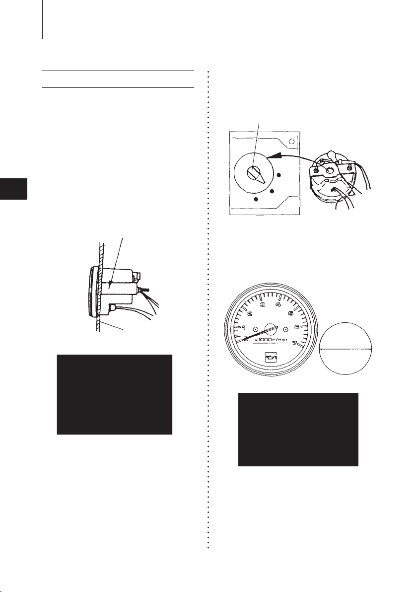
4. Installing the meters
I n s ta l l t h e m e te r s s e cu r e l y i n
t h e d a s h b o a r d w h e r e t h e y
ca n be ea s i l y re a d a n d ar e no t
exp o sed to wa t e r sp l as h e s. Th e
recommended dashboard thickness is
2~11mm(0.08~0.4 in.). For dashboards
thicker than 11mm(0.4 in.), the fitting
plate should be cut accordingly. Be
sure to tighten the fitting nuts on the
fitting plate evenly.
A
l
l models of the 40D2 and 50 D 2
series have six electric poles. Set the
tachometer selector knob to “6P”.
Cu
t h o l es wi t h 85 mm (3 . 3 4 6 in. )
diame t e r f o r th e t a c h o mete r an d
52.5mm (2.067 in.) for the trim meter.
The dashboard inclination should be
50°~70°
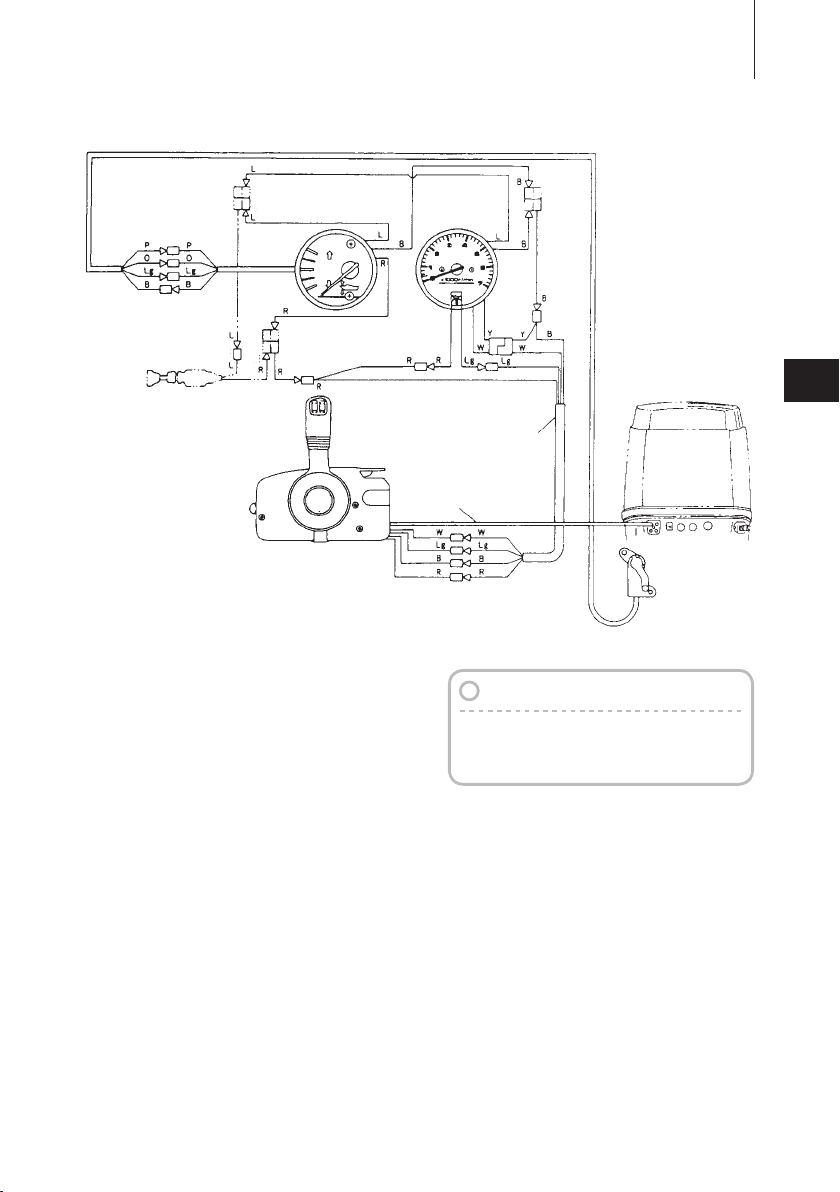
Trim meter
Cable harness B
Meter cable
Meter lamp switch
(option)
Tachometer
Trim sender
*
*
*
*
*
*
Connection of leads
■
Tachometer : EPO EPTO
Trim meter : EPTO
Trim sender : EPTO
Note
INSTALLATION
27
3
Color Code
■
B : black
L : blue
Lg : light green
O : orange
P : pink
R : red
Sb : sky blue
W : white
Y : yellow
The parts of * mark is to be wired when
a Meter Lamp Switch (option) is fixed.
 Loading...