

Tohatsu MFS 8A3, MFS 9.8A3 User Manual
OWNER’S
MANUAL
MFS
8A3
9.8A3
OB No.003-11082-5

READ THIS MANUAL BEFORE USING THE OUTBOARD MOTOR. FAILURE TO FOLLOW THE
!
INSTRUC TIO NS AND SAFETY PRECA UTI ONS IN THIS MANUAL CAN RESULT IN SERIOUS
INJURY OR DEATH. KEEP THIS MANUAL IN A SAFE LOCATION FOR FUTURE REFERENCE.
Copyright © 2009 Tohatsu Corporation. All rights reserved. No part of this manual may
be reproduced or transmitted in any from or by any means without the express written
permission of Tohatsu Corporation.

YOUR TOHATSU OUTBOARD MOTOR
OWNER REGISTRATION AND IDENTIFICATION
Upon purchasing this product, be sure that the WARRANTY CARD is correctly and
completely filled out and mailed to the addressee noted there on. This WARRANTY
CARD identifies you as the legal owner of the product and serves as your warranty
registration.
IF THIS PROCEDURE IS NOT FOLLOWED, YOUR OUTBOARD MOTOR WILL
NOT BE COVERED BY THE APPLICABLE LIMITED WARRANTY.
PRE-DELIVERY CHECK
Be sure that the product has been checked by an authorized TOHATSU dealer
before you take delivery.
Limited Warranty
Please refer to the TOHATSU outboard motor Limited warranty provided to you with
this product, the terms and conditions of which, as amended from time to time, are
incorporated by reference into the manual.

Serial Number
In the space below, please record the outboard motor's serial number (indicated
both on the lower motor cover and on the cylinder block). The serial number will be
needed in the event of theft or to quickly identifying the outboard motor type.
Serial Number :
To You, Our Customer
Thank you for selecting a TOHATSU outboard motor. You are now the proud owner
of an excellent outboard motor that will service you for many years to come.
This manual should be read in its entirety and the inspection and maintenance
procedures described later in this manual should be followed carefully. Should
a problem arise with the outboard motor, please follow the troubleshooting
procedures listed at the end of this manual. If the problem persists, contact an
authorized TOHATSU service shop or dealer.
We hope you will enjoy your outboard motor and wish you good luck in your
boating adventures.
TOHATSU CORPORATION

CONTENTS
GENERAL SAFETY INFORMATION
■
SPECIFICATIONS
1
■
NAMES OF PARTS
2
■
INSTALLATION
3
■
・・・・・・・・・・・・・・・・・・・・・・・・・・・・・・・・・・・・・・・・・・・・・・・・・・・
・・・・・・・・・・・・・・・・・・・・・・・・・・・・・・・・・・・・・・・・・・・・・・・・・・
・・・・・・・・・・・・・・・・・・・・・・・・・・・・・・・・・・・・・・・・・・・・・・・・・・・・・
1. Mounting the outboard motor on boat
2. Installing the remote control devices
3. Installing the battery
PRE-OPERATING PREPARATIONS
4
■
1.Gasoline and engine oil
2.Break-in
・・・・・・・・・・・・・・・・・・・・・・・・・・・・・・・・・・・・・・・・・・・・・・・・・・・・・・・・・
3.Engine oil warning lamp
4.ESG
ENGINE OPERATION
5
■
Before starting
1.Starting
・・・・・・・・・・・・・・・・・・・・・・・・・・・・・・・・・・・・・・・・・・・・・・・・・・・・・・・・・・・・
・・・・・・・・・・・・・・・・・・・・・・・・・・・・・・・・・・・・・・・・・・・・・・・・・・・・・
・・・・・・・・・・・・・・・・・・・・・・・・・・・・・・・・・・・・・・・・・・・・・・・・・・・・・・・・・・
2.Warming up the engine
3.Forward and reverse
4.Stopping
5.Trim angle
・・・・・・・・・・・・・・・・・・・・・・・・・・・・・・・・・・・・・・・・・・・・・・・・・・・・・・・・・
・・・・・・・・・・・・・・・・・・・・・・・・・・・・・・・・・・・・・・・・・・・・・・・・・・・・・・・
・・・・・・・・・・・・・・・・・・・・・・・・・・・・・・・・・・・・・・・・・・・・・・
・・・・・・・・・・・・・・・・・・・・・・・・・・・・・・・・・・・・・・・・・・・・
・・・・・・・・・・・・・・・・・・・・・・・・・・・・・・・・・・・・・・・・・・・
・・・・・・・・・・・・・・・・・・・・・・・・・・・・・・・・・・・・・・・・・・・・・・・
・・・・・・・・・・・・・・・・・・・・・・・・・・・・・・・・・・・・・・・・・・・・
・・・・・・・・・・・・・・・・・・・・・・・・・・・・・・・・・・・・・・・・・・・・・・
6.Tilt up, tilt down and shallow water operation
7.Shallow water operation
REMOVING AND CARRYING THE OUTBOARD MOTOR
6
■
・・・・・・・・・・・・・・・・・・・・・・・・・・・・・・・・・・・・・・・・・・・
1.Removing the outboard motor
2.Carrying the outboard motor
3.Storing the outboard motor
TRAILERING
7
■
ADJUSTMENT
8
■
1.Steering friction
2.Throttle grip
3.Reverse lock
・・・・・・・・・・・・・・・・・・・・・・・・・・・・・・・・・・・・・・・・・・・・・・・・・・・・・・・
・・・・・・・・・・・・・・・・・・・・・・・・・・・・・・・・・・・・・・・・・・・・・・・・・・・・・・
・・・・・・・・・・・・・・・・・・・・・・・・・・・・・・・・・・・・・・・・・・・・・・・・・・・
・・・・・・・・・・・・・・・・・・・・・・・・・・・・・・・・・・・・・・・・・・・・・・・・・・・・・・
・・・・・・・・・・・・・・・・・・・・・・・・・・・・・・・・・・・・・・・・・・・・・・・・・・・・・
4.Remote Control Lever Load
5.Trim Tab Adjustment
INSPECTION AND MAINTENANCE
9
■
1.Daily inspection
2.Periodic inspection
3.Off-season storage
4.Pre-season check
・・・・・・・・・・・・・・・・・・・・・・・・・・・・・・・・・・・・・・・・・・・・・・
・・・・・・・・・・・・・・・・・・・・・・・・・・・・・・・・・・・・・・・・・・・・・・・・・・
・・・・・・・・・・・・・・・・・・・・・・・・・・・・・・・・・・・・・・・・・・・・・・・・
・・・・・・・・・・・・・・・・・・・・・・・・・・・・・・・・・・・・・・・・・・・・・・・・
・・・・・・・・・・・・・・・・・・・・・・・・・・・・・・・・・・・・・・・・・・・・・・・・
5.Motor submerged in water
6.Cold weather precautions
・・・・・・・・・・・・・・・・・・・・・・・・・・・・・・・・・・・・・・・・・・
7.Checking after striking underwater object
TROUBLESHOOTING
10
■
TOOL KIT AND SPARE PARTS
11
■
OPTIONAL ACCESSORIES
12
■
PROPELLER TABLE
13
■
・・・・・・・・・・・・・・・・・・・・・・・・・・・・・・・・・・・・・・・・・・・・・・・
・・・・・・・・・・・・・・・・・・・・・・・・・・・・・・・・・・・・・・・・・・
・・・・・・・・・・・・・・・・・・・・・・・・・・・・・・・・・・・・・・・・・・・・・・・・
・・・・・・・・・・・・・・・・・・・・・・・・・・・・・・・・・・・
・・・・・・・・・・・・・・・・・・・・・・・・・・・・・・・
・・・・・・・・・・・・・・・・・・・・・・・・・・・・・・・・
・・・・・・・・・・・・・・・・・・・・・・・・・・・・・・・・・・・
・・・・・・・・・・・・・・・・・・・・・・・・・
・・・・・・・・・・・・・・・・・・・・・・・・・・・・・・・・・・・・・・
・・・・・・・・・・・・・・・・・・・・・・・・・・・・・・・・・・・・・・・
・・・・・・・・・・・・・・・・・・・・・・・・・・・・・・・・・・・・・・・・・
・・・・・・・・・・・・・・・・・・・・・・・・・・・・・・・・・・・・・・・・
・・・・・・・・・・・・・・・・・・・・・・・・・・・・・・・・・・・
・・・・・・・・・・・・・・・・・・・・・・・・・・・・・・・・・・・・・・・・・
・・・・・・・・・・・・・・・・・・・・・・・・・・・・
・・・・・・・・・・・・・・・・・・・・・・・・・・・・・・・・・・・・・・・
・・・・・・・・・・・・・・・・
8
10
12
14
14
17
20
21
21
23
24
24
25
25
25
30
31
33
34
39
41
43
43
43
43
44
45
45
45
45
46
46
47
48
54
59
60
60
61
61
62
65
66
67

INDEX
7
GENERAL SAFETY INFORMATION
1. SPECIFICATIONS
2. NAMES OF PARTS
3. INSTALLATION
4.PRE-OPERATING PREPARATIONS
5.ENGINE OPERATION
6.
REMOVING AND CARRYING THE OUTBOARD MOTOR
7.TRAILERING
8.ADJUSTMENT
9.INSPECTION AND MAINTENANCE
1
2
3
4
5
6
7
8
9
10.TROUBLESHOOTING
11.TOOL KIT AND SPARE PARTS
12.OPTIONAL ACCESSORIES
13.PROPELLER TABLE
10
11
12
13
!
!
!
GENERAL SAFETY INFORMATION
!
NOTICE : DANGER/WARNING/CAUTION/Note
Before installing, operating or otherwise handling your outboard motor, be sure
to thoroughly read and understand this Owner's Manual and carefully follow all of
the instructions. Of particular importance is information preceded by the words
"DANGER," "WARNING," "CAUTION," and "Note." Always pay special attention to
such information to ensure safe operation of the outboard motor at all times.
Failure to observe will result in severe personal injury or death, and possibly property damage.
Failure to observe could result in severe personal injury or death, or property damage.
Failure to observe could result in personal injury or property damage.
Note
This instruction provides special information to facilitate the use or maintenance of the
outboard motor or to clarify important points.
EMERGENCY STOP SWITCH
The Emergency Stop Switch will stall the outboard motor when the stop switch
tether is pulled off. This stop switch tether can be attached to the operator of
the outboard motor to minimize or prevent injuries from the propeller in case the
operator falls overboard.
We highly recommend use of the Emergency Stop Switch tether.
Accidental activation of the Emergency Stop Switch (such as the tether being pulled out
in heavy seas) could cause passengers to lose their balance and even fall overboard, or it
could result in loss of power in heavy seas, strong currents, or high winds. Loss of control
while mooring is another potential hazard.
To minimize accidental activation of the Emergency Stop Switch, the 500 mm (20 inch.)
stop switch tether is coiled and can extended to a full 1,300 mm (51 inch.).
SAFE OPERATION OF BOAT
!
As the operator/driver of the boat, you are responsible for the safety of those
aboard and those in other boat around yours, and for following local boating
regulations. You should be thoroughly knowledgeable on how to correctly operate
the boat, outboard motor, and accessories. To learn about the correct operation
and maintenance of the outboard motor, please read through this manual carefully.
It is very difficult for a person standing or floating in the water to take evasive action
should he or she see a power boat heading in his /her direction, even at a slow
speed. Therefore, when your boat is in the immediate vicinity of people in the water,
the outboard motor should be shifted to neutral and shut off.
SERIOUS INJURY IS LIKELY IF A PERSON IN THE WATER MAKES CONTACT WITH
A MOVING BOAT, GEAR HOUSING, PROPELLER, OR ANY SOLID DEVICE RIGIDLY
ATTACHED TO A BOAT OR GEAR HOUSING.
SERVICING, REPLACEMENT PARTS & LUBRICANTS
We re commend th at on ly an authori zed ser vice sho p per f orm se rvice or
maintenance on this outboard motor. Be sure to use genuine parts, genuine
lubricants, or recommended lubricants.
MAINTENANCE
As the owner of this outboard motor, you should be acquainted with correct
maintenance procedures. It is the operator's responsibility to perform all safety
checks and to ensure that all lubrication and maintenance instructions are
complied with for safe operation. Please comply with all instructions concerning
lubrication and maintenance. You should take the engine to an authorized dealer
or service shop for periodic inspection at the prescribed intervals.
Correct periodic maintenance and proper care of this outboard motor will reduce
the chance of problems and limit overall operating expenses.
MOUNTING
Outboard motor mounting must be performed by trained service person(s) using
lift or hoist with sufficient capacity.

10
SPECIFICATIONS
MF , EF , EP
1
2
3
4
5
6
7
8
9
10
11
12
13
14
Item
Overall Length mm (in)
Overall Width mm (in)
Overall Height S·L·UL mm (in)
Transom Height S·L·UL
Weight
Output kW (Hp)
Max. Operating Range rpm
Idle Speed in Forward Gear rpm
Idle Speed in Neutral Gear rpm
Engine Type
Number of Cylinder
Bore × Stroke mm (in)
Piston Displacement mL (Cu in)
Exhaust System
Cooling System
Engine Lubrication
Startring System
Ignition System
Spark Plug
Trim Position
Engine Oil
Gear Oil
Fuel Tank Capacity L (US gal)
Gear Reduction Ratio
: with manual
*
Specifications subject to change without notice.
※
MODEL
mm (in)
S Kg (lb)
L Kg (lb)
UL Kg (lb)
8A3 9.8A3
MF EF EP
975 (38.4) 590 (23.2)
354 (13.9) 320 (12.6)
1,035 (40.7) · 1,162 (45.7) · 1,289 (50.7)
435 (17.1) · 562 (22.1) · 689 (27.1)
37.0 (81.5) 40.0 (88.0) 40.0 (88.0)
38.0 (84.0) 41.0 (90.5) 41.0 (90.5)
39.5 (87.0) 42.5 (93.5) 42.5 (93.5)
5.9 (8) 7.2 (9.8)
5,000-6,000
900
950
4-Stroke
2
55 × 44 (2.17 × 1.73)
209 (12.8)
Through hub exhaust
Water cooling
Trochoid pump
Manual Electric starter motor
Flywheel Magneto C.D. ignition
NGK DCPR6E
6 3
NMMA FC-W certified 10W-30 or
API SF, SG, SH, SJ, SL or SM, 10W-30/40, Approx. 800mL
Genuine Gear Oil or API GL5,
SAE #80-90, Approx. 320mL
12 (3.17)
2.08 (13 : 27)
*

EFT , EPT
SPECIFICATIONS
11
Item
Overall Length mm (in)
Overall Width mm (in)
Overall Height S·L·UL mm (in)
Transom Height S·L·UL
Weight
Output kW (Hp)
Max. Operating Range rpm
Idle Speed in Forward Gear rpm
Idle Speed in Neutral Gear rpm
Engine Type
Number of Cylinder
Bore × Stroke mm (in)
Piston Displacement mL (Cu in)
Exhaust System
Cooling System
Engine Lubrication
Startring System
Ignition System
Spark Plug
Trim Position
Engine Oil
Gear Oil
Fuel Tank Capacity L (US gal)
Gear Reduction Ratio
: with manual
*
Specifications subject to change without notice.
※
MODEL
mm (in)
S Kg (lb)
L Kg (lb)
UL Kg (lb)
8A3 9.8A3
EFT EPT
975 (38.4) 590 (23.2)
354 (13.9) 320 (12.6)
1,035 (40.7) · 1,162 (45.7) · 1,289 (50.7)
435 (17.1) · 562 (22.1) · 689 (27.1)
46.5 (102.5) 46.0 (101.4)
47.5 (104.7) 47.0 (103.6)
49.0 (108) 48.5 (106.9)
5.9 (8) 7.2 (9.8)
5,000-6,000
900
950
4-Stroke
2
55 × 44 (2.17 × 1.73)
209 (12.8)
Through hub exhaust
Water cooling
Trochoid pump
Electric starter motor
Flywheel Magneto C.D. ignition
NGK DCPR6E
6 3
NMMA FC-W certified 10W-30 or
API SF, SG, SH, SJ, SL or SM, 10W-30/40, Approx. 800mL
Genuine Gear Oil or API GL5,
SAE #80-90, Approx. 320mL
12 (3.17)
2.08 (13 : 27)
*
1
2
3
4
5
6
7
8
9
10
11
12
13
○
1
○
2
○
3
○
8
○
9
○
11
○
10
○
13
○
14
○
15
○
16
○
17
○
18
○
23
○
20
○
19
○
21
○
22
○
12
○
4
○
5
○
6
○
7
○
24
○
26
○
28
○
27
○
29
○
30
○
31
○
32
○
33
○
34
EP type only
○
35
○
25
1
2
3
4
5
12
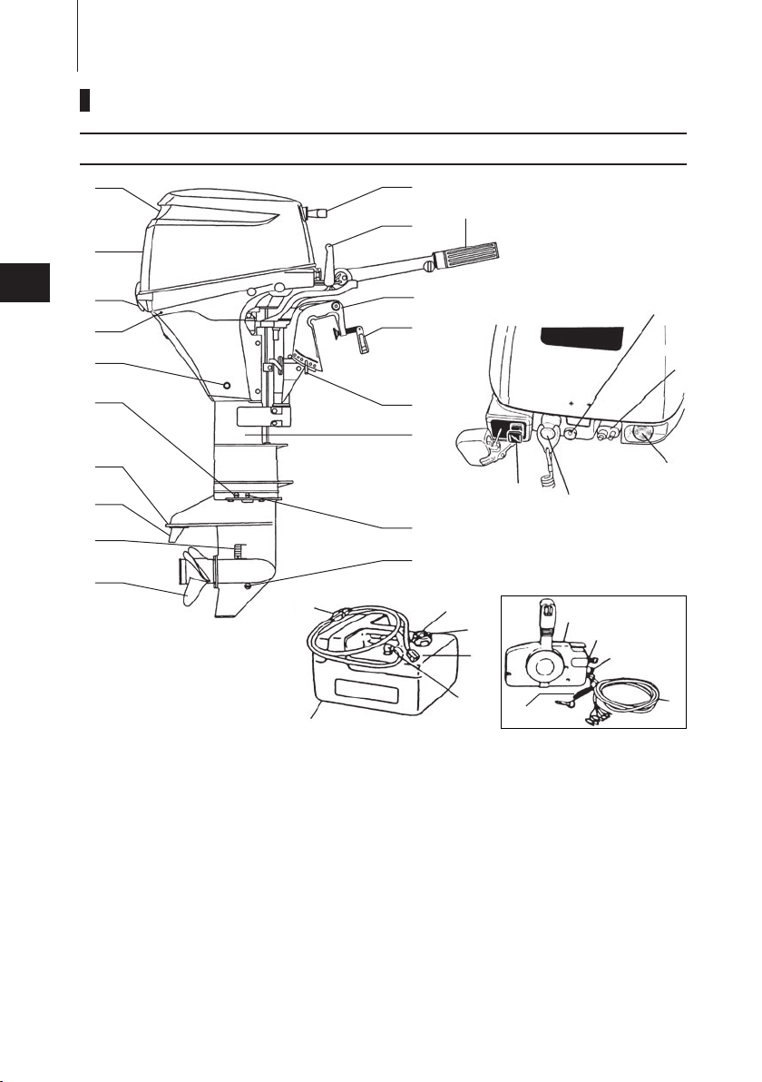
NAMES OF PARTS
MF , EF , EP
10
11
12
13
14
6
7
8
9
MF and EF type only.
*:
EF type only.
☆:
①
Tilt Handle
②
Top Cowl
③
Cowl Latch
④
Cooling Water Check Port
⑤
Oil Drain Bolt
⑥
Water Plug
⑦
Anti Ventilation Plate
⑧
Anode / Trim Tab
⑨
Water Inlet
⑩
Propeller
11
○
Oil Plug (Lower) (Fill)
12
○
Oil Plug (Upper) (Level)
13
○
Drive Shaft Housing
14
○
Thrust Rod
15
○
Clamp Bracket
16
○
Clamp Screw
17
○
Shift Lever
*
18
○
Throttle Grip
*
19
○
Starter Handle
20
○
Warning Lamp
21
○
Fuel Connector
22
○
Starter Switch
☆
23
○
Stop Switch
24
○
Choke Knob
*
25
○
26
○
27
○
28
○
29
○
30
○
31
○
32
○
33
○
34
○
35
○
Primer Bulb
Fuel Tank Cap
Air Vent Screw
Fuel Connector
Fuel Pick up Elbow
Fuel Tank
Remote Control Box
Main Switch
Stop Switch
Cord Assembly
Engine Stop Switch Cord
○
23
○
20
○
21
○
22
○
24
○
26
○
28
○
27
○
29
○
30
○
31
○
32
○
33
○
34
EPT type only
○
35
○
25
○
1
○
2
○
3
○
8
○
9
○
11
○
10
○
13
○
14
○
15
○
16
○
17
○
18
○
19
○
12
○
4
○
5
○
6
○
7
○
16
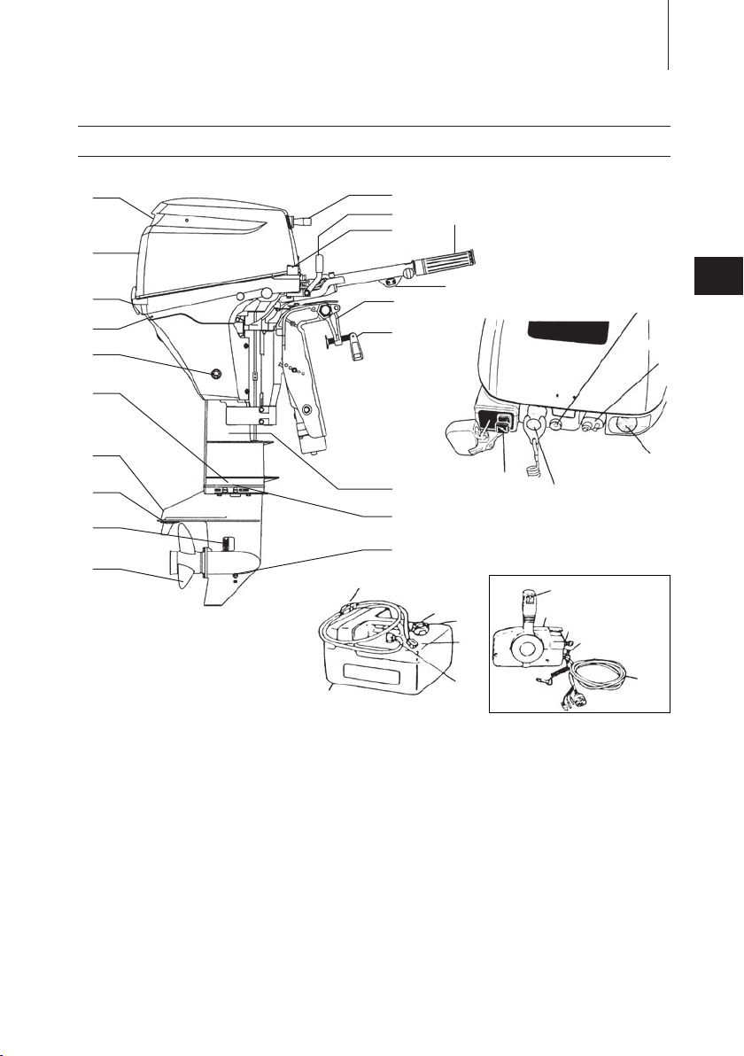
EFT , EPT
NAME OF PARTS
13
1
2
3
4
5
EFT type only.
*:
EPT type only.
☆:
①
Tilt Handle
②
Top Cowl
③
Cowl Latch
④
Cooling Water Check Port
⑤
Oil Drain Bolt
⑥
Water Plug
⑦
Anti Ventilation Plate
⑧
Anode / Trim Tab
⑨
Water Inlet
⑩
Propeller
11
○
Oil Plug (Lower) (Fill)
12
○
Oil Plug (Upper) (Level)
13
○
Drive Shaft Housing
14
○
Clamp Bracket
15
○
Clamp Screw
16
○
Power tilt switch
*
17
○
Throttle Grip
*
18
○
Shift Lever
*
19
○
Starter Handle
20
○
Oil warning Lamp
21
○
Fuel Connector
22
○
Starter Switch
☆
23
○
Stop Switch
24
○
Choke Knob
*
25
○
26
○
27
○
28
○
29
○
30
○
31
○
32
○
33
○
34
○
35
○
Primer Bulb
Fuel Tank Cap
Air Vent Screw
Fuel Connector
Fuel Pick up Elbow
Fuel Tank
Remote Control Box
Main Switch
Stop Switch
Cord Assembly
Engine Stop Switch Cord
6
7
8
9
10
11
12
13
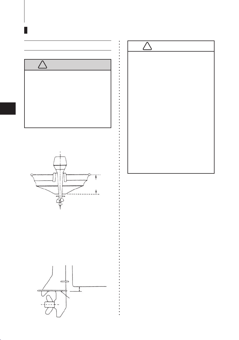
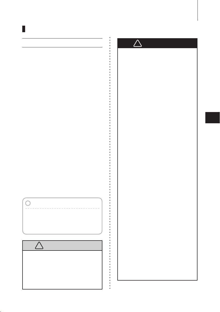
Bottom of hull
Anti Ventilation Plate
5-25mm
(0.2-1”)
1
!
Boat Transom
Center of Boat
!
2
3
4
5
6
14
INSTALLATION
1. Mounting the outboard motor on boat
Most boats are rated and certified
in terms of their maximum allowable
horsepower, as shown on the boat’s
certification plate. Do not equip your boat
with an outboard motor that exceeds this
limit. If in doubt, contact your dealer.
Do not operate the outboard motor until it
has been securely mounted on the boat
in accordance with the instructions below.
Position ... Above keel line
Set engine at center of boat.
Before beginning the running test,
●
check that the boat with maximum
capacity loading floats on the water in
a proper attitude. Check the position
of water surface on the driveshaft
housing. If the water surface is near
the bottom cowling, in high waves,
water may enter the engine cylinders.
Incorrect outboard motor mounting
●
height or existence of underwater
object(s), such as hull bottom
design, bottom surface conditions or
underwater accessories, can cause
production of water spray possibly
reaching the engine through an
opening of the bottom cowling
during cruising. Exposing engine
to such conditions for extended
periods can lead to severe engine
damage.
7
8
9
10
11
Transom matching
Be sure that the anti ventilation plate of
the outboard motor is below the water
surface when running with the throttle
wide open.
If the above condition cannot be met
due to the shape of the bottom of your
boat, please consult your authorized
dealer.
12
13
14
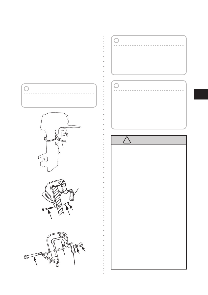
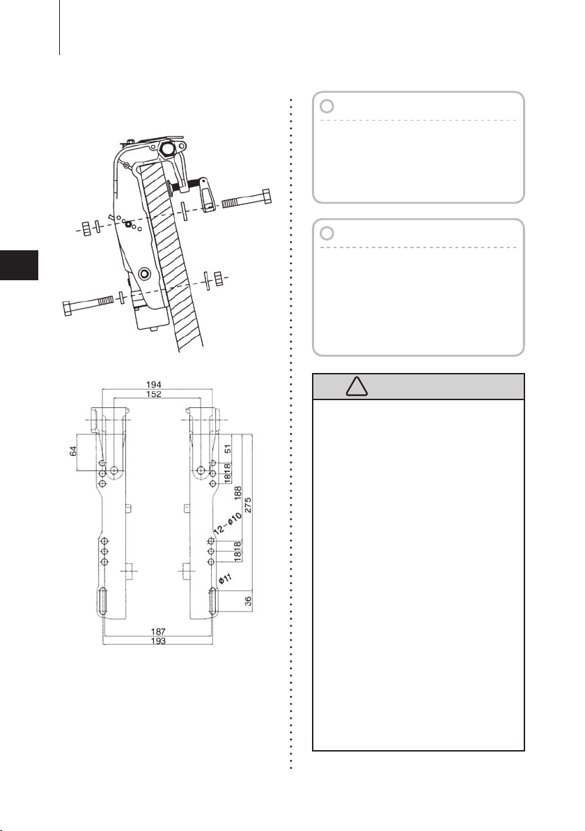
INSTALLATION
!
Clamp Screw
Nut
Washer
Bolt
EP
*
Bolt (8×85)
Clamp Screw
*
Nut
*
Washer
*
: Option
MF & EF
*
: Option
15
MF, EF, EP type
To attach the outboard motor to the
①
boat, tighten the clamp screws by
turning their handles.
Al so, tighten the bolts. S e cure
the outboard motor with a rope to
prevent loss overboard.
Note
The rope is not included in the standard
accessories.
Note
It is recommended to install upper
mounting bolts with bolt head at
inside surface of transom. Bolts with
threaded end at inside surface of
transom can cause personal injury.
1
2
Notes
1. Apply sealing agent such as silicone
sealed between the bolts and
transom board holes before tightening
the bolts.
2. Be sure to tighten mounting bolt nuts
to the specified torque.
(30 Nm(3.0kgf)13ft·lb)
3
4
5
Mounting outboard motor without
●
following this manual can lead to unsafe
conditions such as poor maneuverability,
going out of control or fire disaster.
Loose clamp screws and/or mounting
●
bolts can lead to coming off or
displacement of outboard motor,
possibly going out of control or causing
serious personal injury. Be sure that
fasteners are tightened to the specified
torque (30 Nm (3.0kgf)13ft·lb). Check
fasteners for tightness from time to time.
Be sure to use outboard mounting
●
fasteners included in outboard motor
package delivered or their equivalents
in terms of size, material, quality and
strength.
Tighten fasteners to the specified torque
(30 Nm (3.0kgf)13ft·lb). Test cruise
to check if fasteners are tightened
securely.
Outboard motor mounting must be
●
performed by trained service person(s)
using lift or hoist with sufficient capacity.
6
7
8
9
10
11
12
13
INSTALLATION
!
16
1
2
3
4
5
6
7
8
9
10
11
12
13
EFT, EPT type (Power tilt model)
Note
It is recommended to install upper
mounting bolts with bolt head at
inside surface of transom. Bolts with
threaded end at inside surface of
transom can cause personal injury.
Notes
1. Apply sealing agent such as silicone
sealed between the bolts and
transom board holes before tightening
the bolts.
2. Be sure to tighten mounting bolt nuts
to the specified torque.
(30 Nm(3.0kgf)13ft·lb)
Mounting outboard motor without
●
following this manual can lead to unsafe
conditions such as poor maneuverability,
going out of control or fire disaster.
Loose clamp screws and/or mounting
●
bolts can lead to coming off or
displacement of outboard motor,
possibly going out of control or causing
serious personal injury. Be sure that
fasteners are tightened to the specified
torque (30 Nm (3.0kgf)13ft·lb). Check
fasteners for tightness from time to time.
Be sure to use outboard mounting
●
fasteners included in outboard motor
package delivered or their equivalents
in terms of size, material, quality and
strength.
Tighten fasteners to the specified torque
(30 Nm (3.0kgf)13ft·lb). Test cruise
to check if fasteners are tightened
securely.
Outboard motor mounting must be
●
performed by trained service person(s)
using lift or hoist with sufficient capacity.
14
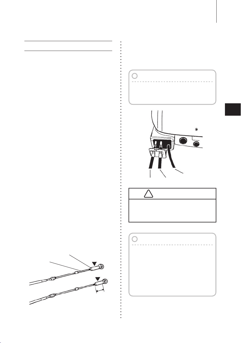
2.
Cable joint
Approx. 10mm
(0.39 inch)
Remoto control cable
Lock nut
Cable Harness
Throttle CableShift Cable
!
Installing the remote control devices
It is recommended that you consult
wi t h yo u r au t ho r i ze d d e al e r fo r
insta llation and adj ustment of the
remote control device.
Installation of the Remote Control
■
Cables (Box side) :
Follow the instruction manual
provided with the remote control.
Installation of the Remote Control
■
on your boat :
Follow the instruction manual
provided with the remote control.
Installation of the Remote Control
■
Cable (engine side) and the Cord
Assembly (Wiring Harness) :
INSTALLATION
Fitting of Remote Control Cable to
②
Engine.
Note
Put the control lever in the Neutral
position and the Free Accel lever in
the fully closed position.
17
1
2
3
4
5
6
Fitt i n g of connecting parts to
①
cables
Screw the tip of the remote control
cabl e in to th e ca ble jo i nt up to
approx. 10 mm (0.39 inch), then lock
them with a lock nut. Apply grease to
the hole of the cable joint.
Be careful not to loop remote control
cables to diameter of 406 mm (16
inches) or less.
Note
Confirm the engine shifts correctly
when the shif t lever is placed in
Forward and Reverse position. also
confirm the throttle valve is closed
at idle, in Neutral, Forward, and
Reverse. Confirm the throttle valve
is fully open when in Forward at the
wide open position.
7
8
9
10
11
12
13
Green
Green
Red
Red
Red
Red
Blue
Blue
Blue
Yellow
Brown
Brown
Brown
Brown
Black
Black
Black
Drag link
Sleeve
From
Remote
Control Box
Brown
Brown
Black
Black
Green
Blue
Red
1
!
2
3
4
5
6
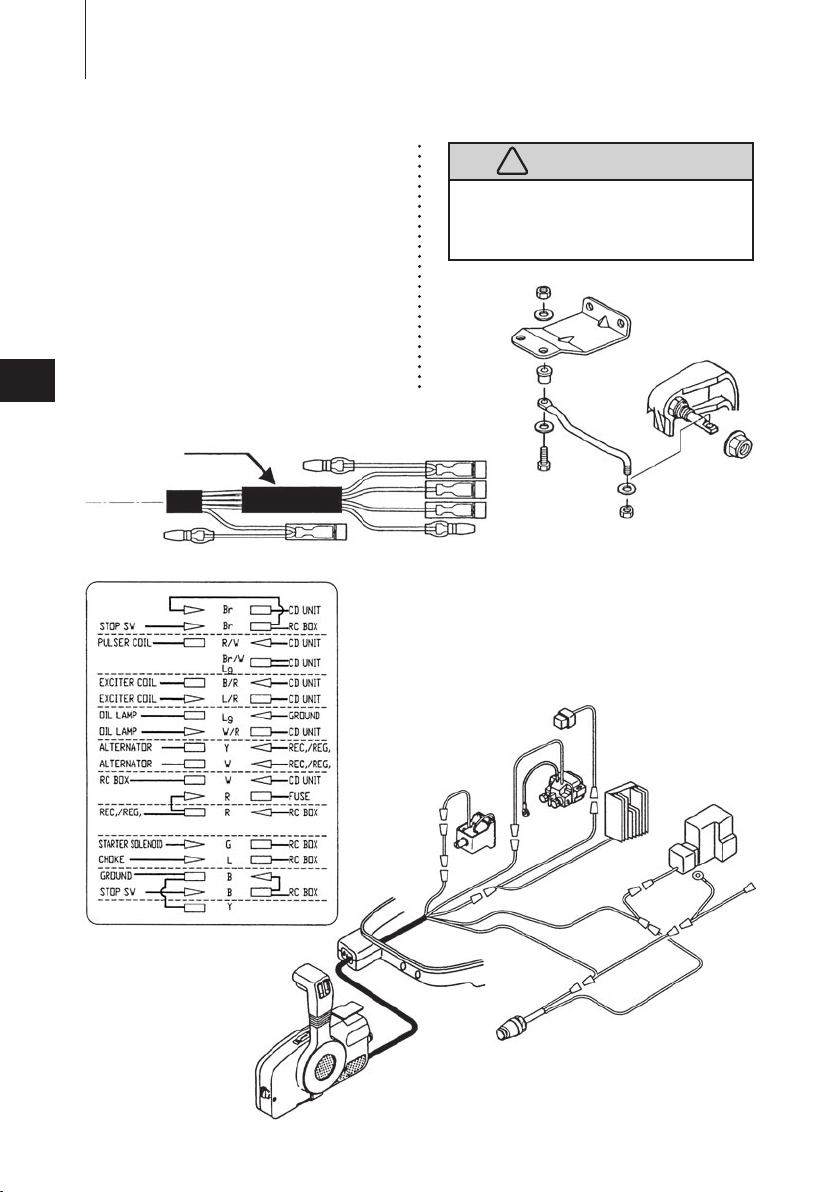
INSTALLATION
18
Connecting the Cord assembly
③
(Wiring Harness)
Pass the Cord asse mbly from t he
Remote cont rol bo x th rou g h th e
hole in the Lower motor cover and
cover the wire ends with the Sleeve
(provided in a t ool bag) and then
co n n e c t th e el e c t r i c t e r m i n a l s
according to the drawing below.
EP model
Do not disconnect cord ass'y when
engine is in operation, or engine will go
out of control.
7
8
9
10
11
12
13
14
EP model
Green
Green
Red
Red
Red
Red
Blue
Blue
Blue
Yellow
Brown
Brown
Brown
Brown
Black
Black
Black
Red
Sky blue
Pink
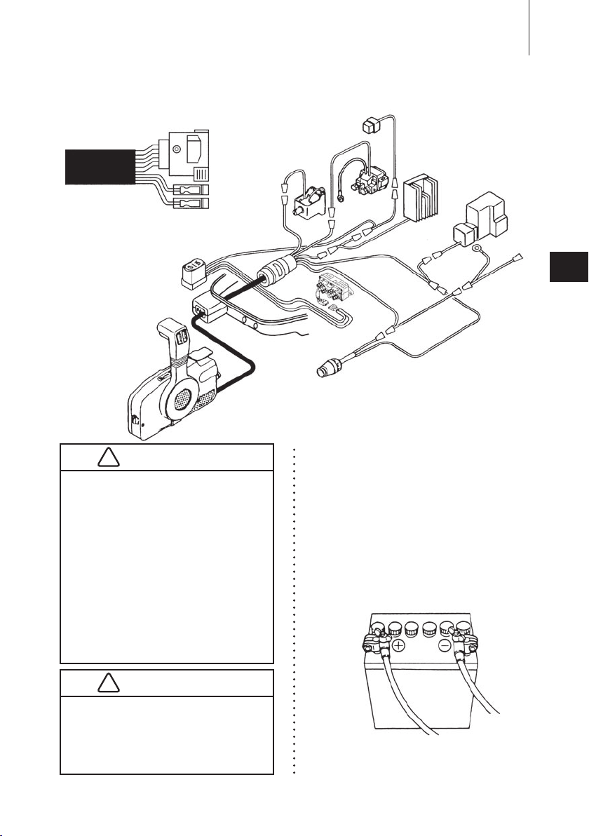
EPT model
!
Battery cord
(black)
Battery cord
(red)
!
Make sure that the battery cords do
●
not get stuck between the outboard
motor and boat when turning, etc.
The starter motor may fail to
●
operate if the cords are incorrectly
connected.
Be sure to correctly connect the (+)
●
and (−) cords. If not, the charging
system will be damaged.
Do not disconnect the battery cords
●
from battery while the engine is
operating, the electrical parts could
be damaged.
Always use a fully charged battery.
●
Do not use a battery that is not
recommended. Use of a battery
not recommended can lead to poor
performance of, and / or damage to,
the electrical system.
Connect the positive cord (+) to the
②
positive terminal (+) of the battery,
and then connect the negative
co rd (−). Wh e n dis c o nnectin g
th e batt ery alw ays remov e the
neg a t iv e cord (− ) fi r s t. Af ter
connecting the positive terminal
(+), securely place a cap on it to
prevent short circuits.
INSTALLATION
19
1
2
3
4
5
6
7
8
9
10
11
12
13
INSTALLATION
!
!
20
3. Installing the battery
1
2
3
4
5
6
7
8
9
P l a c e t h e b a t te ry b o x i n a
①
co nven ient pos itio n away fro m
water spray. Securely fasten both
the box and the battery so they do
not shake loose.
Note
Minimum recommended battery : 12V,
70AH or 12V, 40AH
Specifications and features of batteries
vary among the manufacturers. Consult
the manufacturer for details.
Battery generates explosive hydrogen
gas. Be sure to:
Charge the battery in a well-ventilated
●
place.
Place the battery away from any
●
source of fire, sparks and open
flames such as burners or welding
equipment.
Do not smoke when handling the
●
battery.
Do not smoke near the battery when
●
the battery is charging.
Battery electrolyte contains sulfuric acid
and thus is hazardous, causing a burn
if it comes in contact with your skin, or
poisonous if swallowed.
KEEP BATTERY AND ELECTROLYTE
AWAY FROM REACH OF CHILDREN
When handling the battery, be sure to:
Read all warnings shown on the
●
battery case
Prevent electrolyte from coming in
●
contact with any part of your body.
Contact can cause serious burn or,
if it comes in contact with your eye,
loss of sight. Use safety glasses and
rubber gloves.
In case battery electrolyte comes in
contact with:
Skin, flush thoroughly with water.
●
Eye, flush thoroughly with water,
●
and then seek immediate medical
treatment.
In case battery electrolyte is swallowed:
Seek immediate medical treatment.
●
10
11
12
13
14
PRE-OPERATING PREPARATIONS
!
!
1. Gasoline and engine oil
21
Required Gasoline types
UNITED STATES AND CANADA:
Us e a ma jor br and o f auto moti ve
unleaded gasoline with a minimum
po s ted octa n e rating of 87. Midgra d e au t o mo t i ve ga sol i ne th a t
contain fuel injector cleaner a re
preferred for added internal engine
cleanliness. Leaded gasoline is not
recommended.
INTERNATIONAL :
Us e a ma jor br and o f auto moti ve
unleaded gasoline with a minimum
posted octane rating of 91RON.
Au t omotiv e gas o line tha t contai n
fuel injector cleaner are preferred for
added internal engine cleanliness.
Leaded gasoline is accep table in
areas where unleaded gasoline is not
available.
Note
Use of low-quality gasoline results in
a short engine life as well as starting
difficulties and other engine problems.
We recommend use for Fuel stabilizer.
Do not fill the fuel tank over capacity.
The rise of gasoline temperature may
cause gasoline to expand which, if
overfilled, may leak through an air vent
screw when it is open. Leaking gasoline
is a dangerous fire hazard.
Consult an authorized dealer for details
on handling of gasoline, if necessary.
Gasoline and its vapors are very
flammable and can be explosive.
When carrying a fuel tank containing
gasoline :
Close the air vent screw of fuel
●
tank cap, or gasoline vapor will be
emitted through the air vent screw,
creating a fire hazard.
Do not smoke.
●
When or before refueling :
Stop the engine, and do not start the
●
engine during refueling.
Do not smoke.
●
Be careful not to overfill fuel tank.
●
Wipe up any spilled gasoline
immediately.
When or before cleaning the gasoline tank :
Dismount fuel tank from the boat.
●
Place the fuel tank away from every
●
source of ignition, such as sparks or
open flames.
Do the work outdoors or in well
●
ventilated area.
Wipe up any spilled gasoline
●
immediately.
After cleaning gasoline tank :
Wipe up any spilled gasoline
●
immediately.
If the fuel tank is disassembled for
●
cleaning, reassemble carefully.
Imperfect assembly may cause a
fuel leak, possibly leading to fire or
explosion.
Dispose of aged or contaminated
●
gasoline in accordance with local
regulations.
1
2
3
4
5
6
7
8
9
10
11
12
13
!
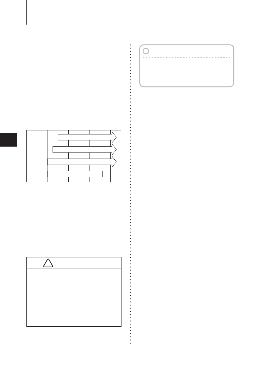
20W−40, 20W−50
15W−40, 15W−50
10W−40, 10W−50
10W−30
Atmospheric temp.
˚C
˚F
40
96
30
86
20
68
10
50
0
32
-10
14
-20
-4
-30
-22
ENGINE
OIL
PRE-OPERATING PREPARATIONS
22
1
2
3
4
5
6
7
8
9
Engine Oil
Us e onl y hig h qu a li ty 4- s t ro k e
engine oil to insure performance and
prolonged engine life.
Use NMMA FC-W certified 4-stroke
engine oil below.
10W-30: is recommended for use in
all temperature.
25W-40: may be used at temperatures
above 4˚C (40˚F).
You can also use oils that carry the
API rating of SF, SG, SH, SJ, SL, or
SM. Select the appropriate viscosity,
based on atmospheric temperature,
from the chart below.
Note
Use of engine oils that do not meet
these requirements will result in
reduced engine life, and other engine
problems.
10
11
12
THE ENGINE OIL IS DRAINED FOR
SHIPPING FROM THE FACTORY. BE
SURE TO FILL THE ENGINE TO THE
PROPER LEVEL BEFORE STARTING
ENGINE. (TO PROPERLY FILL THE
ENGINE WITH OIL FOLLOW THE
INSTRUCTIONS IN SECTION 9 OF
THIS MANUAL)
13
14
 Loading...