

TOHATSU MFS 6A3Z 8A3 9.8A3, MFS 6A3Z, MFS 8A3, MFS 9.8A3 Owner's Manual
MANUAL
OWNER’S
OB No.003-11082-9
6A3Z
8A3
9.8A3
MFS

ENOM00001-0
READ THIS MANUAL BEFORE USING THE OUTBOARD MOTOR. FAILURE TO FOLLOW THE
INSTRUCTIONS AND SAFETY PRECAUTIONS IN THIS MANUAL CAN RESULT IN SERIOUS
INJURY OR DEATH. KEEP THIS MANUAL IN A SAFE LOCATION FOR FUTURE REFERENCE.
Copyright © 2009-2012 Tohatsu Corporation. All rights reserved. No part of this manual may be reproduced
or transmitted in any from or by any means without the express written permission of Tohatsu Corporation.

YOUR TOHATSU OUTBOARD MOTOR
ENOM00002-0
OWNER REGISTRATION AND IDENTIFICATION
Upon purchasing this product, be sure that the WARRANTY CARD is correctly and completely filled out and mailed to the addressee noted there on. This WARRANTY CARD
identifies you as the legal owner of the product and serves as your warranty registration.
TO THE EXTENT PERMITTED BY APPLICABLE LAW, YOUR OUTBOARD MOTOR WILL
NOT BE COVERED BY THE APPLICABLE LIMITED WARRANTY, IF THIS PROCEDURE IS
NOT FOLLOWED.
ENOM00003-0
PRE-DELIVERY CHECK
Be sure that the product has been checked by an authorized TOHATSU dealer before you
take delivery.
ENOM00004-0
Limited Warranty
Please refer to the TOHATSU outboard motor Limited warranty provided to you with this
product, the terms and conditions of which, as amended from time to time, are incorporated by reference into the manual.
3

4
ENOM00005-0
Serial Number
In the space below, please record the outboard motor’s serial number (indicated both on
the lower motor cover and on the cylinder block). The serial number will be needed in the
event of theft or to quickly identifying the outboard motor type.
Serial Number:
ENOM00006-0
To You, Our Customer
Thank you for selecting a TOHATSU outboard motor. You are now the proud owner of an
excellent outboard motor that will service you for many years to come.
This manual should be read in its entirety and the inspection and maintenance procedures
described later in this manual should be followed carefully. Should a problem arise with the
outboard motor, please follow the troubleshooting procedures listed at the end of this
manual. If the problem persists, contact an authorized TOHATSU service shop or dealer.
We hope you will enjoy your outboard motor and wish you good luck in your boating
adventures.
TOHATSU CORPORATION

CONTENTS
GENERAL SAFETY INFORMATION. . . . . . . . . . . . . . . . . . . . . . . . . . . . . . . . 8
1. SPECIFICATIONS . . . . . . . . . . . . . . . . . . . . . . . . . . . . . . . . . . . . . . . . . . . . . 10
2. NAMES OF PARTS . . . . . . . . . . . . . . . . . . . . . . . . . . . . . . . . . . . . . . . . . . . .13
3. LOCATIONS OF WARNING LABELS . . . . . . . . . . . . . . . . . . . . . . . . . . . . . .15
4. INSTALLATION . . . . . . . . . . . . . . . . . . . . . . . . . . . . . . . . . . . . . . . . . . . . . . . 19
1. Mounting the outboard motor on boat . . . . . . . . . . . . . . . . . . . . . . . . . . .19
2. Installing the remote control devices . . . . . . . . . . . . . . . . . . . . . . . . . . . . . 22
3. Installing the battery. . . . . . . . . . . . . . . . . . . . . . . . . . . . . . . . . . . . . . . . . . 26
5. PRE-OPERATING PREPARATIONS . . . . . . . . . . . . . . . . . . . . . . . . . . . . . .27
1. Recommended gasoline types . . . . . . . . . . . . . . . . . . . . . . . . . . . . . . . . .27
2. Low permeation fuel hose requirement . . . . . . . . . . . . . . . . . . . . . . . . . . .28
EQUIPPED FOR UNITED STATES AND CANADA MODEL
3. EPA pressurized portable fuel tank requirements . . . . . . . . . . . . . . . . . . . 29
EQUIPPED FOR UNITED STATES AND CANADA MODEL
4. EPA approval primer valve/hose assembly . . . . . . . . . . . . . . . . . . . . . . . . 29
EQUIPPED FOR UNITED STATES AND CANADA MODEL
5. Recommended engine oil . . . . . . . . . . . . . . . . . . . . . . . . . . . . . . . . . . . . . 30
6. Altitude adjustment kit requirement. . . . . . . . . . . . . . . . . . . . . . . . . . . . . .30
7. Break-In . . . . . . . . . . . . . . . . . . . . . . . . . . . . . . . . . . . . . . . . . . . . . . . . . . . 31
8. Engine oil warning lamp. . . . . . . . . . . . . . . . . . . . . . . . . . . . . . . . . . . . . . .32
9. ESG (A device preventing over revolution). . . . . . . . . . . . . . . . . . . . . . . . . 32
6. ENGINE OPERATION . . . . . . . . . . . . . . . . . . . . . . . . . . . . . . . . . . . . . . . . . . 33
Before starting . . . . . . . . . . . . . . . . . . . . . . . . . . . . . . . . . . . . . . . . . . . . . . . . 33
1. Filling the fuel . . . . . . . . . . . . . . . . . . . . . . . . . . . . . . . . . . . . . . . . . . . . . . . 33
2. Feeding the fuel . . . . . . . . . . . . . . . . . . . . . . . . . . . . . . . . . . . . . . . . . . . . .34
3. Starting. . . . . . . . . . . . . . . . . . . . . . . . . . . . . . . . . . . . . . . . . . . . . . . . . . . . 36
4. Warming up the engine . . . . . . . . . . . . . . . . . . . . . . . . . . . . . . . . . . . . . . .41
5. Forward and reverse . . . . . . . . . . . . . . . . . . . . . . . . . . . . . . . . . . . . . . . . . 41
6. Stopping. . . . . . . . . . . . . . . . . . . . . . . . . . . . . . . . . . . . . . . . . . . . . . . . . . . 43
7. Trim angle . . . . . . . . . . . . . . . . . . . . . . . . . . . . . . . . . . . . . . . . . . . . . . . . .44
8. Tilt up, tilt down and shallow water operation . . . . . . . . . . . . . . . . . . . . . . 49
9. Shallow water operation . . . . . . . . . . . . . . . . . . . . . . . . . . . . . . . . . . . . . .52
7. REMOVING AND CARRYING THE OUTBOARD MOTOR. . . . . . . . . . . . . . 54
1. Removing the outboard motor. . . . . . . . . . . . . . . . . . . . . . . . . . . . . . . . . .54
2. Carrying the outboard motor . . . . . . . . . . . . . . . . . . . . . . . . . . . . . . . . . . .54
3. Storing the outboard motor . . . . . . . . . . . . . . . . . . . . . . . . . . . . . . . . . . . .54
8. TRAILERING . . . . . . . . . . . . . . . . . . . . . . . . . . . . . . . . . . . . . . . . . . . . . . . . .55
9. ADJUSTMENT . . . . . . . . . . . . . . . . . . . . . . . . . . . . . . . . . . . . . . . . . . . . . . . . 56
1. Steering friction . . . . . . . . . . . . . . . . . . . . . . . . . . . . . . . . . . . . . . . . . . . . .56
2. Throttle grip . . . . . . . . . . . . . . . . . . . . . . . . . . . . . . . . . . . . . . . . . . . . . . . . 56
3. Remote Control Lever Load. . . . . . . . . . . . . . . . . . . . . . . . . . . . . . . . . . . .56
4. Trim Tab Adjustment . . . . . . . . . . . . . . . . . . . . . . . . . . . . . . . . . . . . . . . . . 57
10. INSPECTION AND MAINTENANCE . . . . . . . . . . . . . . . . . . . . . . . . . . . . . . . 58

1. Daily Inspection . . . . . . . . . . . . . . . . . . . . . . . . . . . . . . . . . . . . . . . . . . . . . 59
2. Periodic Inspection . . . . . . . . . . . . . . . . . . . . . . . . . . . . . . . . . . . . . . . . . .65
3. Off-season storage . . . . . . . . . . . . . . . . . . . . . . . . . . . . . . . . . . . . . . . . . .69
4. Pre-season check . . . . . . . . . . . . . . . . . . . . . . . . . . . . . . . . . . . . . . . . . . .70
5. Motor submerged in water. . . . . . . . . . . . . . . . . . . . . . . . . . . . . . . . . . . . . 70
6. Cold weather precautions . . . . . . . . . . . . . . . . . . . . . . . . . . . . . . . . . . . . .71
7. Checking after striking underwater object. . . . . . . . . . . . . . . . . . . . . . . . . 71
11. TROUBLESHOOTING . . . . . . . . . . . . . . . . . . . . . . . . . . . . . . . . . . . . . . . . . .72
12. TOOL KIT AND SPARE PARTS . . . . . . . . . . . . . . . . . . . . . . . . . . . . . . . . . . 74
13. OPTIONAL ACCESSORIES . . . . . . . . . . . . . . . . . . . . . . . . . . . . . . . . . . . . .75
14. PROPELLER TABLE . . . . . . . . . . . . . . . . . . . . . . . . . . . . . . . . . . . . . . . . . . .76
INDEX
7
GENERAL SAFETY INFORMATION
1. SPECIFICATIONS
2. NAMES OF PARTS
3. LOCATIONS OF WARNING LABELS
4. INSTALLATION
5. PRE-OPERATING PREPARATIONS
6. ENGINE OPERATION
7. REMOVING AND CARRYING THE
OUTBOARD MOTOR
8. TRAILERING
9. ADJUSTMENT
10.INSPECTION AND MAINTENANCE
11.TROUBLESHOOTING
12.TOOL KIT AND SPARE PARTS
13.OPTIONAL ACCESSORIES
14.PROPELLER TABLE

8
GENERAL SAFETY INFORMATION
ENOM00007-0
NOTICE: DANGER/WARNING/CAUTION/Note
Before installing, operating or otherwise handling your outboard motor, be sure to thoroughly read and understand this Owner’s Manual and carefully follow all of the instructions. Of particular importance is information preceded by the words “DANGER,”
“WARNING,” “CAUTION,” and “Note.” Always pay special attention to such information to
ensure safe operation of the outboard motor at all times.
ENOW00001-0
DANGER
Failure to observe will result in severe personal injury or death, and possibly property damage.
ENOW00002-0
WARNING
Failure to observe could result in severe personal injury or death, or property damage.
ENOW00003-0
CAUTION
Failure to observe could result in personal injury or property damage.
ENON00001-0
Note
This instruction provides special information to facilitate the use or maintenance of the outboard
motor or to clarify important points.
ENOM0008-0
EMERGENCY STOP SWITCH
The Emergency Stop Switch will stall the outboard motor when the stop switch tether is
pulled off. This stop switch tether can be attached to the operator of the outboard motor
to minimize or prevent injuries from the propeller in case the operator falls overboard.
We highly recommend use of the Emergency Stop Switch tether.
ENOW00004-0
WARNING
Accidental activation of the Emergency Stop Switch (such as the tether being pulled out in
heavy seas) could cause passengers to lose their balance and even fall overboard, or it
could result in loss of power in heavy seas, strong currents, or high winds. Loss of control
while mooring is another potential hazard.
To minimize accidental activation of the Emergency Stop Switch, the 500 mm (20 inch.) stop
switch tether is coiled and can extended to a full 1300 mm (51 inch.).
GENERAL SAFETY INFORMATION 9
ENOM00009-0
SAFE OPERATION OF BOAT
As the operator/driver of the boat, you are responsible for the safety of those aboard and
those in other boat around yours, and for following local boating regulations. You should
be thoroughly knowledgeable on how to correctly operate the boat, outboard motor, and
accessories. To learn about the correct operation and maintenance of the outboard motor,
please read through this manual carefully.
It is very difficult for a person standing or floating in the water to take evasive action should
he or she see a power boat heading in his/her direction, even at a slow speed. Therefore,
when your boat is in the immediate vicinity of people in the water, the outboard motor
should be shifted to neutral and shut off.
ENOW00005-0
WARNING
SERIOUS INJURY IS LIKELY IF A PERSON IN THE WATER MAKES CONTACT WITH A MOVING BOAT, GEAR HOUSING, PROPELLER, OR ANY SOLID DEVICE RIGIDLY ATTACHED TO
A BOAT OR GEAR HOUSING.
ENOM00010-0
SERVICING, REPLACEMENT PARTS & LUBRICANTS
We recommend that only an authorized service shop perform service or maintenance on
this outboard motor. Be sure to use genuine parts, genuine lubricants, or recommended
lubricants.
ENOM00011-0
MAINTENANCE
As the owner of this outboard motor, you should be acquainted with correct maintenance
procedures. It is the operator’s responsibility to perform all safety checks and to ensure
that all lubrication and maintenance instructions are complied with for safe operation.
Please comply with all instructions concerning lubrication and maintenance. You should
take the engine to an authorized dealer or service shop for periodic inspection at the prescribed intervals.
Correct periodic maintenance and proper care of this outboard motor will reduce the
chance of problems and limit overall operating expenses.
ENOM00012-0
MOUNTING
Outboard motor mounting must be performed by trained service person(s) using lift or
hoist with sufficient capacity.

10
SPECIFICATIONS
ENOM00501-0
6A3Z (Available in specific region)
Item MODEL MF EF EP
Overall Length mm (in) 975 (38.4) 590 (23.2)
Overall Width mm (in) 354 (13.9) 320 (12.6)
Overall Height S·L·UL mm (in) 1035 (40.7) 1162 (45.7) 1289 (50.7)
Transom Height S·L·UL mm (in) 435 (17.1) 562 (22.1) 689 (27.1)
S kg (lb) 37.0 (81.5) —
Weight
Output kW (ps) 4.4 (6)
Max. Operating Range rpm 5000–6000
Idle Speed in Forward Gear rpm 900
Idle Speed in Neutral Gear rpm 950
Engine Type 4-Stroke
Number of Cylinder 2
Bore × Stroke mm (in) 55 × 44 (2.17 × 1.73)
Piston Displacement mL (Cu in) 209 (12.8)
Exhaust System Through hub exhaust
Cooling System Water cooling
Engine Lubrication Trochoid pump
Startring System Manual Electric starter motor*
Ignition System Flywheel Magneto C.D. ignition
Spark Plug NGK DCPR6E
Tri m Po sition 6 3
Engine Oil mL (fl.oz.)
Gear Oil mL (fl.oz.) Genuine Gear Oil or API GL5, SAE #80-90, Approx. 320 (10.8)
Fuel
Fuel Tank Capacity L (US gal) 12 (3.17)
Gear Reduction Ratio 2.08 (13 : 27)
Emission Control System EM (Engine modification)
Operator Sound Pressure
(ICOMIA 39/94) dB (A)
Hand Vibration Level
(ICOMIA 38/94) m/sec2
*: with manual
Remark: Specifications subject to change without notice.
L kg (lb) 38.0 (84.0) 41.0 (90.5)
UL kg (lb) 39.5 (87.0) —
NMMA FC-W certified 10W-30 or
API SF, SG, SH, SJ, SL or SM, 10W-30/40, Approx. 800 (27)
Unleaded regular gasoline : Pump posted
87 Octane (research octane rating of 91)
77.2
2.2 —

ENOM00502-0
8A3, 9.8A3
SPECIFICATIONS 11
Item MODEL
Overall Length mm (in) 975 (38.4) 590 (23.2)
Overall Width mm (in) 354 (13.9) 320 (12.6)
Overall Height S·L·UL mm (in) 1035 (40.7) 1162 (45.7) 1289 (50.7)
Transom Height S·L·UL mm (in) 435 (17.1) 562 (22.1) 689 (27.1)
S kg (lb) 37.0 (81.5) 40.0 (88.0)
Weight
Output kW (ps) 5.9 (8) 7.2 (9.8)
Max. Operating Range rpm 5000–6000
Idle Speed in Forward Gear rpm 900
Idle Speed in Neutral Gear rpm 950
Engine Type 4-Stroke
Number of Cylinder 2
Bore × Stroke mm (in) 55 × 44 (2.17 × 1.73)
Piston Displacement mL (Cu in) 209 (12.8)
Exhaust System Through hub exhaust
Cooling System Water cooling
Engine Lubrication Trochoid pump
Startring System Manual Electric starter motor*
Ignition System Flywheel Magneto C.D. ignition
Spark Plug NGK DCPR6E
Tri m Po sition 6 3
Engine Oil mL (fl.oz.)
Gear Oil mL (fl.oz.) Genuine Gear Oil or API GL5, SAE #80-90, Approx. 320 (10.8)
Fuel
Fuel Tank Capacity L (US gal) 12 (3.17)
Gear Reduction Ratio 2.08 (13 : 27)
Emission Control System EM (Engine modification)
Operator Sound Pressure
(ICOMIA 39/94) dB (A)
Hand Vibration Level
(ICOMIA 38/94) m/sec2
*: with manual
Remark: Specifications subject to change without notice.
L kg (lb) 38.0 (84.0) 41.0 (90.5)
UL kg (lb) 39.5 (87.0) 42.5 (93.5)
8A3 9.8A3
MF EF EP
NMMA FC-W certified 10W-30 or
API SF, SG, SH, SJ, SL or SM, 10W-30/40, Approx. 800 (27)
Unleaded regular gasoline : Pump posted
87 Octane (research octane rating of 91)
77.2
2.2 —

SPECIFICATIONS12
ENOM00503-0
8A3, 9.8A3
Item MODEL
Overall Length mm (in) 975 (38.4) 590 (23.2)
Overall Width mm (in) 354 (13.9) 320 (12.6)
Overall Height S·L·UL mm (in) 1035 (40.7) 1162 (45.7) 1289 (50.7)
Transom Height S·L·UL mm (in) 435 (17.1) 562 (22.1) 689 (27.1)
S kg (lb) 46.5 (102.5) 46.0 (101.4)
Weight
Output kW (ps) 5.9 (8) 7.2 (9.8)
Max. Operating Range rpm 5000–6000
Idle Speed in Forward Gear rpm 900
Idle Speed in Neutral Gear rpm 950
Engine Type 4-Stroke
Number of Cylinder 2
Bore × Stroke mm (in) 55 × 44 (2.17 × 1.73)
Piston Displacement mL (Cu in) 209 (12.8)
Exhaust System Through hub exhaust
Cooling System Water cooling
Engine Lubrication Trochoid pump
Startring System Electric starter motor*
Ignition System Flywheel Magneto C.D. ignition
Spark Plug NGK DCPR6E
Tri m Po sition 6 3
Engine Oil mL (fl.oz.)
Gear Oil mL (fl.oz.) Genuine Gear Oil or API GL5, SAE #80-90, Approx. 320 (10.8)
Fuel
Fuel Tank Capacity L (US gal) 12 (3.17)
Gear Reduction Ratio 2.08 (13 : 27)
Emission Control System EM (Engine modification)
Operator Sound Pressure
(ICOMIA 39/94) dB (A)
Hand Vibration Level
(ICOMIA 38/94) m/sec2
*: with manual
Remark: Specifications subject to change without notice.
L kg (lb) 47.5 (104.7) 47.0 (103.6)
UL kg (lb) 49.0 (108) 48.5 (106.9)
8A3 9.8A3
ET EPT
NMMA FC-W certified 10W-30 or
API SF, SG, SH, SJ, SL or SM, 10W-30/40, Approx. 800 (27)
Unleaded regular gasoline : Pump posted
87 Octane (research octane rating of 91)
77.2
2.2 —
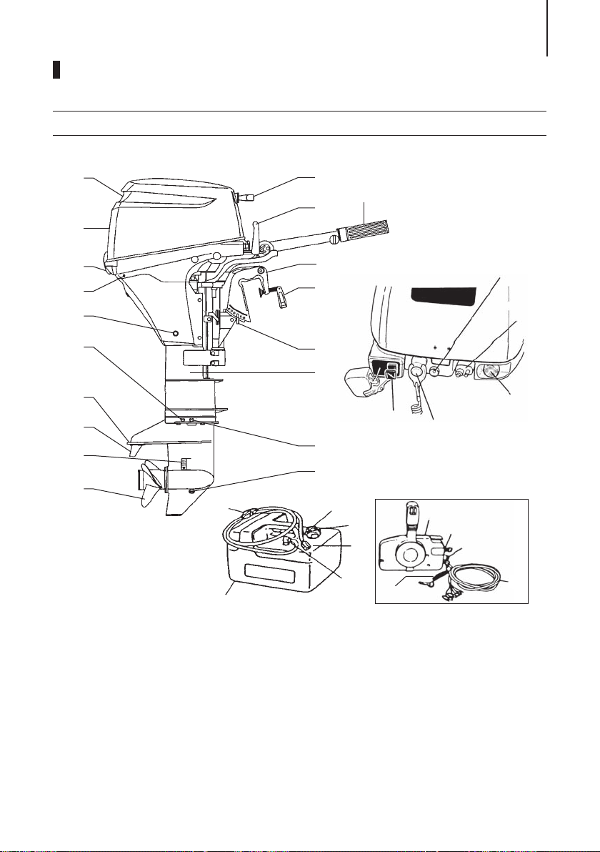
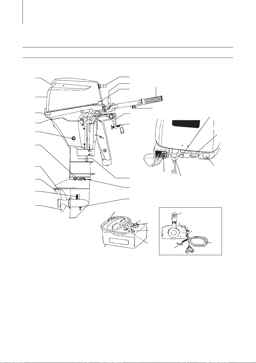
NAMES OF PARTS
ENOM00504-0
MF, EF, EP
13
1
2
3
4
5
6
7
8
9
10
1
Tilt Handle
2
Top Cowl
3
Cowl Latch
4
Cooling Water Check Port
5
Oil Drain Bolt
6
Water Plug
7
Anti Ventilation Plate
8
Anode/Trim Tab
9
Water Inlet
10
Propeller
11
Oil Plug (Lower) (Fill)
12
Oil Plug (Upper) (Level)
13
Drive Shaft Housing
14
Thrust Rod
25
30
15
Clamp Bracket
16
Clamp Screw
17
Shift Lever
18
Throttle Grip
19
Starter Handle
20
Warning Lamp
21
Fuel Connector
22
Starter Switch
23
Stop Switch
24
Choke Knob
25
Primer Bulb
26
Fuel Tank Cap
27
Air Vent Screw
28
Fuel Connector
19
18
17
15
20
16
21
14
13
22
24
23
12
11
26
29
27
28
31
32
33
EP
*3
34
35
ENOF00501-0
29
Fuel Pick up Elbow
30
*1
*1
*2
*1
Fuel Tank
31
Remote Control Box
32
Main Switch
33
Stop Switch
34
Cord Assembly
35
Engine Stop Switch Cord
*1: MF and EF type only.
*2: EF type only.
*3: EP type only.
NAMES OF PARTS14
ENOM00506-0
EFT, EPT
10
1
19
1718
16
2
16
3
4
5
14
15
20
21
6
7
8
9
13
12
24
23
22
11
30
25
26
29
27
28
36
32
31
33
34
EPT
*2
35
1
Tilt Handle
2
Top Cowl
3
Cowl Latch
4
Cooling Water Check Port
5
Oil Drain Bolt
6
Water Plug
7
Anti Ventilation Plate
8
Anode/Trim Tab
9
Water Inlet
10
Propeller
11
Oil Plug (Lower) (Fill)
12
Oil Plug (Upper) (Level)
13
Drive Shaft Housing
14
Clamp Bracket
15
Clamp Screw
16
Power Tilt Switch
17
Throttle Grip
18
Shift Lever
19
Starter Handle
20
Oil warning Lamp
21
Fuel Connector
22
Starter Switch
23
Stop Switch
24
Choke Knob
25
Primer Bulb
26
Fuel Tank Cap
27
Air Vent Screw
28
Fuel Connector
ENOF00502-0
29
*1
*1
*1
*2
*1
Fuel Pick up Elbow
30
Fuel Tank
31
Power Tilt Switch
32
Remote Control Box
33
Main Switch
34
Stop Switch
35
Cord Assembly
36
Engine Stop Switch Cord
*1: EFT type only.
*2: EPT type only.
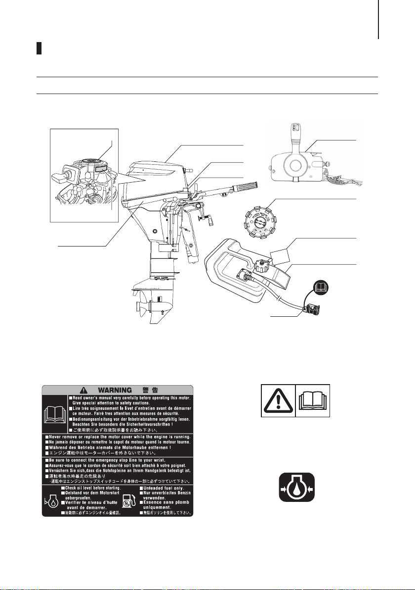
LOCATIONS OF WARNING LABELS
ENOF00120-0
ENOF00131-0
ENOM00507-0
Locations of warning labels
15
6
5
4
1.
Warning label regarding owner’s manual, top cowl, engine stop switch,
engine oil level and unleaded gasoline.
1
2
3
11
ENOF00503-0
2.
Only for EU remote control model
Warning label regarding installation of
remote control system (See page 22).
7
8
9
10
ENOF00005-0
3.
Warning label regarding oil pressure
(See page 32).
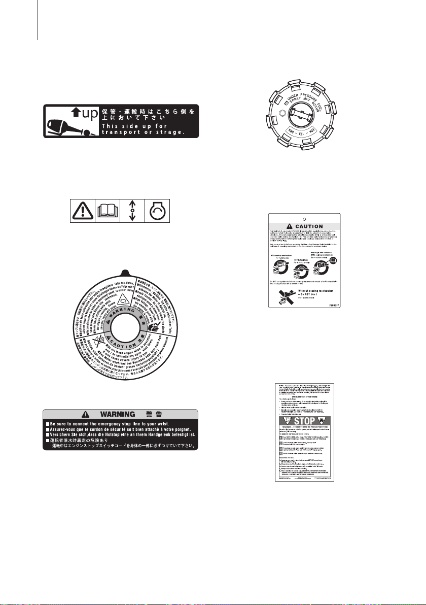
LOCATIONS OF WARNING LABELS16
ENOF00006-0
4.
Warning label on position of outboard
motor when setting down.
5.
Only for EU model
Warning label regarding emergency
starting (See page 38).
ENOF00128-0
6.
Warning label regarding rotating parts,
electrical shock and high temperature.
1
2
ENOF00129-0
7.
Warning label on engine stop switch.
ENOF00012-0
9.
Only for USA and CANADA models
Warning regarding combination of fuel
tank and primer bulb ass’y.
ENOF00010-0
10.
Only for USA and CANADA models
When opening or closing fuel tank cap,
be sure to observe warning note on
fuelling.
8.
Only for USA and CANADA models
Warning regarding fuel tank cap
(See pages 26, 33–36).
ENOF00008-0
11.
Only for USA and CANADA models
Warning regarding fuel connector
(See pages 26, 33–36).
ENOF00011-0
LOCATIONS OF WARNING LABELS 17
ENOF00114-0
ENOF00117-0
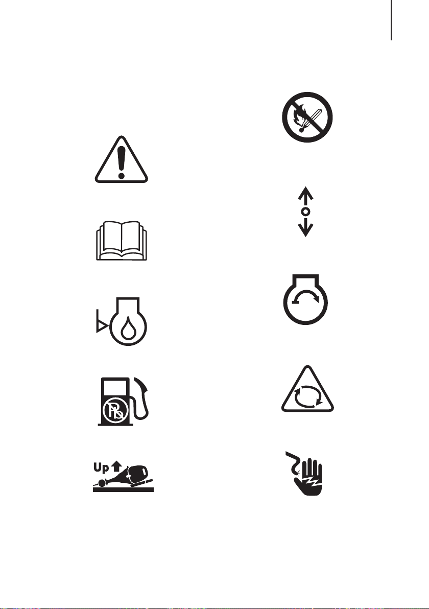
ENOM00508-0
Symbols
Individual symbol marks means as
described below.
Warning/Caution
Read manual thoroughly
ENOF00115-0
Check oil level
ENOF00116-0
Use unleaded gasoline only
Flammable - Keep Fire Away
ENOF00119-0
Gear shift lever operation direction,
dual direction
ENOF00122-0
Engine start/Engine cranking
ENOF00123-0
Warning, rotating object
Lay as indicated
ENOF00118-0
ENOF00249-0
Warning, high voltage
ENOF00204-0

LOCATIONS OF WARNING LABELS18
Warning, high temperature
ENOF00205-0
INSTALLATION
ENOM00024-0
1. Mounting the outboard motor on
boat
ENOW00006-0
WARNING
Most boats are rated and certified in terms
of their maximum allowable horsepower,
as shown on the boat’s certification plate.
Do not equip your boat with an outboard
motor that exceeds this limit. If in doubt,
contact your dealer.
Do not operate the outboard motor until it
has been securely mounted on the boat in
accordance with the instructions below.
ENOM00025-0
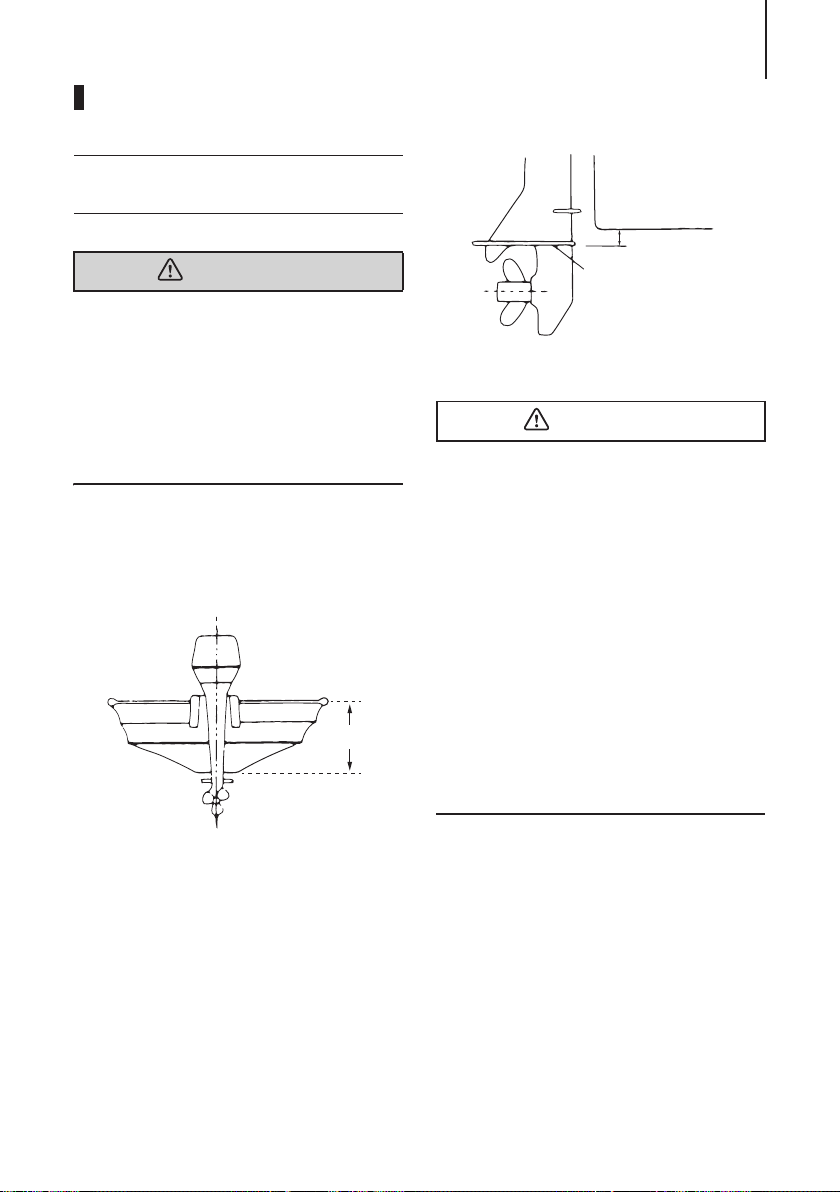
Position ... Above keel line
Set engine at center of boat.
1
2
ENOF00014-0
1. Center of boat
2. Boat transom
ENOM00509-0
Transom matching
Be sure that the anti ventilation plate of the
outboard motor is below the water surface
when running with the throttle wide open.
If the above condition cannot be met due
to the shape of the bottom of your boat,
please consult your authorized dealer.
19
1
5−25 mm
(0.2−1 in)
2
ENOF00015-0
1. Bottom of hull
2. Anti ventilation plate
ENOW00007-0
CAUTION
z Before beginning the running test, check
that the boat with maximum capacity
loading floats on the water in a proper
attitude. Check the position of water
surface on the driveshaft housing. If the
water surface is near the bottom cowling, in high waves, water may enter the
engine cylinders.
z Incorrect outboard motor mounting
height or existence of underwater
object(s), such as hull bottom design,
bottom surface conditions or underwater accessories, can cause water spray
possibly reaching the engine through an
opening of the bottom cowling during
cruising. Exposing the engine to such
conditions for extended periods can
lead to severe engine damage.
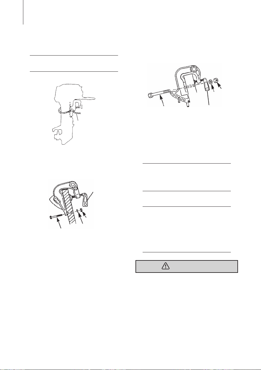
ENOM00510-0
MF, EF, EP type
1. To attach the outboard motor to the
boat, tighten the clamp screws by
turning their handles.
Also, tighten the bolts. Secure the outboard motor with a rope to prevent
loss overboard.
INSTALLATION20
ENON00002-0
Note
A rope is not included in the standard
accessories.
1
ENOF00504-0
1. Option
EP
1
4
3
ENOF00505-0
1. Clamp screw
2. Bolt
3. Washer
4. Nut
2
MF & EF
3*
2*
4
ENOF00506-0
1. Bolt (8 × 85)*
2. Washer*
3. Nut*
4. Clamp screw
*: Option
ENON00510-0
1*
Note
It is recommended to install upper mounting
bolts with bolt head at inside surface of transom. Bolts with threaded end at inside surface of transom can cause personal injury.
ENON00003-0
Notes
1. Apply sealing agent, such as silicone
sealed between the bolts and the transom board holes before tightening the
bolts.
2. Be sure to tighten the mounting bolt
nuts to the specified torque.
(30 Nm (3.0 kgf) 13 ft-lb)
ENOW00009-0
WARNING
z Mounting the outboard motor without
following this manual can lead to unsafe
conditions such as poor maneuverability, lack of control or fire.
z Loose clamp screws and/or mounting
bolts can lead to the release or displacement of the outboard motor, possibly
resulting in lost of control and/or serious
personal injury. Be sure that fasteners
are tightened to the specified torque (30
Nm (3.0 kgf) 13 ft-lb). Check the fasteners for tightness from time to time.
z Be sure to use outboard mounting fas-
teners included in the outboard motor
package or their equivalents in terms of
size, material, quality and strength.
Tighten fasteners to the specified torque
(30 Nm (3.0 kgf) 13 ft-lb). Test cruise to
check if fasteners are tightened
securely.
z Outboard motor mounting must be per-
formed by trained service person(s)
using lift or hoist with sufficient capacity.
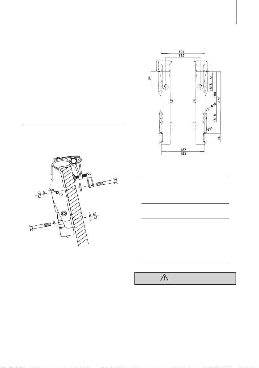
ENOM00511-0
EFT, EPT type (Power tilt model)
ENOF00507-0
INSTALLATION 21
ENOF00508-0
ENON00510-0
Note
It is recommended to install upper mounting
bolts with bolt head at inside surface of transom. Bolts with threaded end at inside surface of transom can cause personal injury.
ENON00003-0
Notes
1. Apply sealing agent, such as silicone
sealed between the bolts and the transom board holes before tightening the
bolts.
2. Be sure to tighten the mounting bolt
nuts to the specified torque.
(30 Nm (3.0 kgf) 13 ft-lb)
ENOW00009-0
WARNING
z Mounting the outboard motor without
following this manual can lead to unsafe
conditions such as poor maneuverability, lack of control or fire.
z Loose clamp screws and/or mounting
bolts can lead to the release or displacement of the outboard motor, possibly
resulting in lost of control and/or serious
INSTALLATION22
personal injury. Be sure that fasteners
are tightened to the specified torque (30
Nm (3.0 kgf) 13 ft-lb). Check the fasteners for tightness from time to time.
z Be sure to use outboard mounting fas-
teners included in the outboard motor
package or their equivalents in terms of
size, material, quality and strength.
Tighten fasteners to the specified torque
(30 Nm (3.0 kgf) 13 ft-lb). Test cruise to
check if fasteners are tightened
securely.
z Outboard motor mounting must be per-
formed by trained service person(s)
using lift or hoist with sufficient capacity.
ENOM00512-0
2. Installing the remote control
devices
ENOW00010-0
WARNING
When using other than Tohatsu’s genuine
remote control box, DO NOT select the one
without neutral safety switch that prevents
in-gear start.
Use of remote control box without neutral
safety switch can allow start of engine with
gear at other than neutral shift, potentially
leading passengers to falling or causing
passenger to be thrown overboard.
It is recommended that you consult with
your authorized dealer for installation and
adjustment of the remote control device.
your boat:
Follow the instruction manual provided
with the remote control.
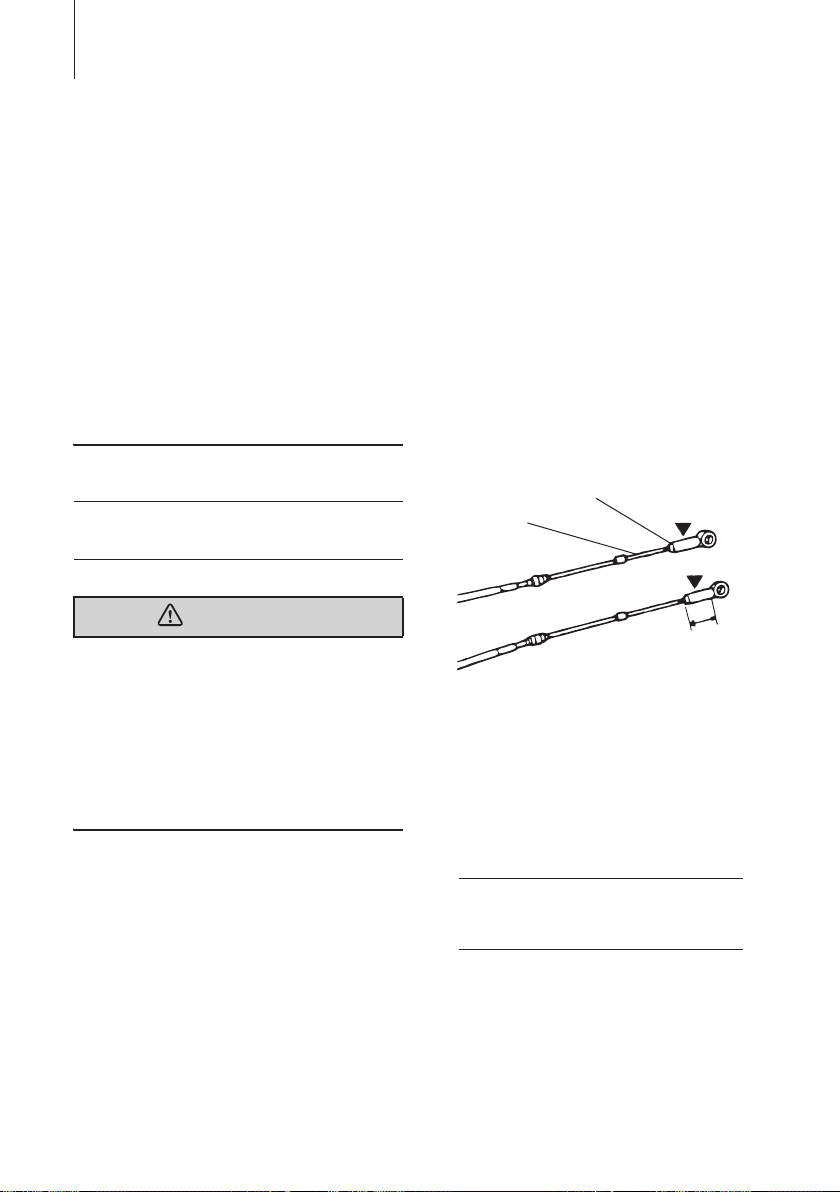
Installation of the Remote Control
Cable (engine side) and the Cord
Assembly (Wiring Harness):
1. Fitting of connecting parts to cables
Screw the tip of the remote control cable
into the cable joint up to approx. 10 mm
(0.39 inch), then lock them with a lock nut.
Apply grease to the hole of the cable joint.
1
1. Remote control cable
2. Lock nut
3. Cable joint
2
3
10 mm
(0.39 in)
ENOF00019-0
2. Fitting of Remote Control Cable to
Engine.
ENON00004-0
Note
Put the control lever in the Neutral position
and the Free Accel lever in the fully closed
position.
Installation of the Remote Control
Cables (Box side):
Follow the instruction manual provided
with the remote control.
Installation of the Remote Control on
INSTALLATION 23
ENOW00011-0
WARNING
Do not disconnect the cord assembly when
the outboard motor is in operation or you
will lose control of the outboard motor.
2
1
1. Shift cable
2. Throttle cable
3. Cable harness
ENOW00100-0
ENOF00510-0
CAUTION
Be careful not to loop the remote control
cables to a diameter of 406 mm (16 inches)
or less.
ENON00005-0
Note
Confirm the outboard motor shifts correctly
when the shift lever is placed in Forward and
Reverse position. also confirm the throttle
valve is closed at idle, in Neutral, Forward,
and Reverse. Confirm the throttle valve is
fully open when in Forward at the wide open
position.
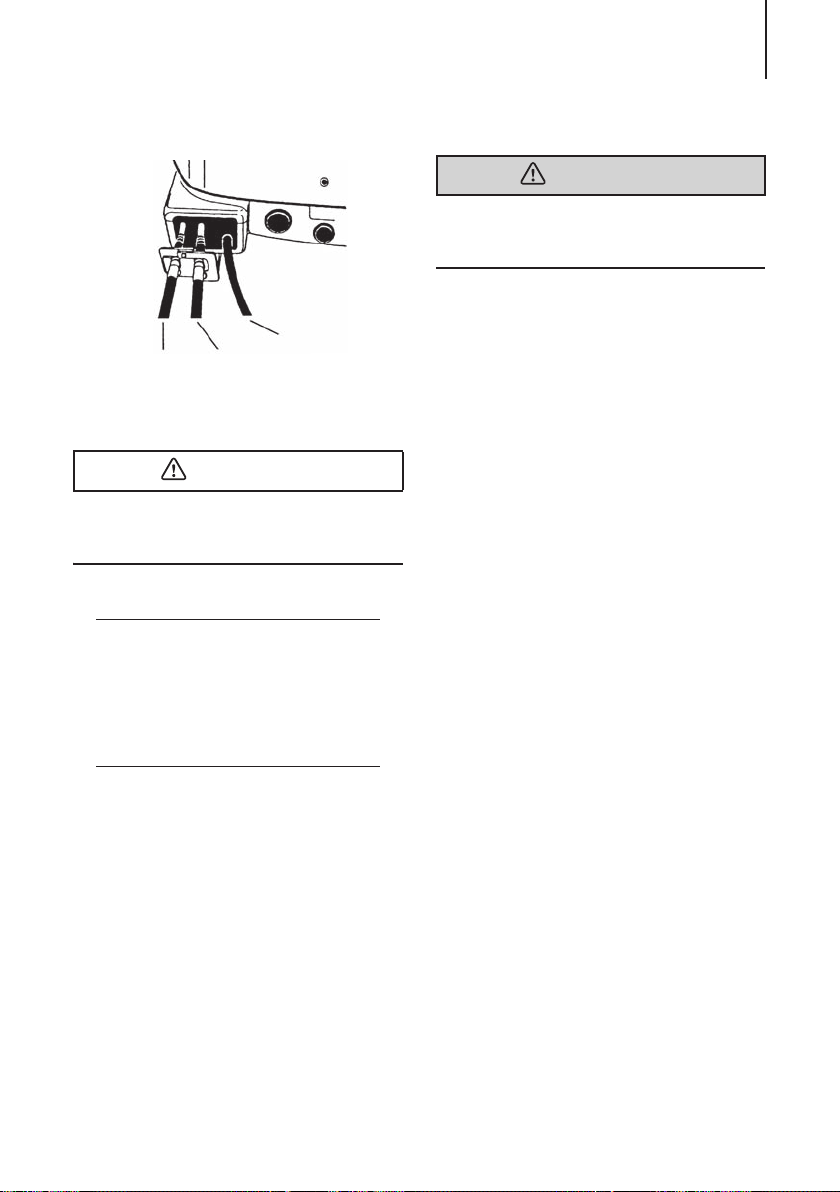
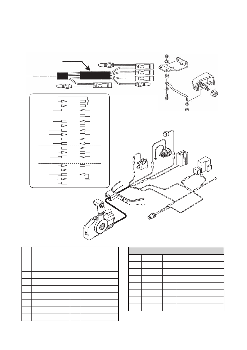
3. Connecting the Cord assembly (Wiring
Harness)
Pass the Cord assembly from the Remote
control box through the hole in the Lower
motor cover and cover the wire ends with
the Sleeve (provided in a tool bag) and
then connect the electric terminals according to the drawing below.
3
INSTALLATION24
EP model
2
1
Br
Br
STOP SW
4
PULSER COIL CD UNIT
5
EXCITER COIL
6
EXCITER COIL
6
DIL LAMP
7
DIL LAMP
7
AL TERNATOR
8
AL TERNATOR
8
RC BOX
9
REC,/REG,
STARTER SOLENOID
11
CHOKE
12
GROUND
13
STOP SW
14
Br
R/W
Br/W
Lg
B/R
L/R
Lg
W/R
Y
W
W
R
R
G
L
B
B
Y
CD UNITBr
RC BOX
CD UNIT
CD UNIT
CD UNIT
GROUND
CD UNIT
REC,/REG,
REC,/REG,
CD UNIT
FUSE
RC BOX
RC BOX
RC BOX
RC BOX
B
B
G
L
R
15
16
15
15
15
15
17
15
10
10
15
18
1610
16
16
16
L
L
G
L
R
G
R
R
3
R
Br
B
Br
YBr
B
B
Br
From remote con-
1
trol box
2 Sleeve 11
10 REC./REG.
STARTER SOLENOID
3 Drag link 12 CHOKE
4 STOP SW 13 GROUND
5 PULSER COIL 14 STOP SW
6 EXCITER COIL 15 CD UNIT
7 OIL LAMP 16 RC BOX
8 ALTERNATOR 17 GROUND
9 RC BOX 18 FUSE
ENOF00568-0
Wire Color
B Black L Blue
Or Orange P Pink
Y Ye ll ow R/W Red with White tracer
W White Br/W Brown with White tracer
Br Brown B/R Black with Red tracer
Sb Sky Blue L/R Blue with Red tracer
G Green W/R White with Red tracer
R Red
 Loading...