

TOHATSU MFS 40A, MFS 50A Owner's Manual

OWNER’S
Original instructions
MANUAL
AAAA
MFS A
MFS A
OB No.--AH

ENOM00001-0
READ THIS MANUAL BEFORE USING THE OU TBOARD MOTOR. FAILURE TO FOLLOW THE INSTRUCTIONS
AND SAFETY PRECAUTIONS IN THIS MANUAL CAN RESULT IN SERIOUS INJURY OR DEATH. KEEP THIS
MANUAL IN A SAFE LOCATION FOR FUTURE REFERENCE.
Copyright © 2018 Tohatsu Corporation. All rights reserved. No part of this manual may be reproduced or
transmitted in any from or by any means without the express written permission of Tohatsu Corporation.

YOUR TOHATSU OUTBOARD MOTOR
ENOM00006-A
To You, Our Customer
Thank you for selecting a TOHATSU outboard motor. You are now the proud owner of
an excellent outboard motor that will service you for many years to come.
This manual should be read in its entirety and the inspection and maintenance procedures described later in this manual should be followed carefully. Should a problem
arise with the outboard motor, please follow the troubleshooting procedures listed at
the end of this manual. If the problem persists, contact an authorized TOHATSU service shop or dealer.
All information in this manual is based on the latest product information available at
the time of approval for printing.
Tohatsu Corporation reserves the right to make changes at any time without notice
and without incurring any obligation.
Please always keep this manual together with the outboard motor as a reference to
everyone who uses the outboard motor. If the outboard motor is resold, make sure
the manual is passed on to the next owner.
3
We hope you will enjoy your outboard motor and wish you good luck in your boating
adventures.
TOHATSU CORPORATION
ENOM00113-0
EC DECLARATION OF CONFORMITY (DoC)
This product conforms to certain portion of the European Parliament directive. DoC
contains the following information;
z Name and Address of the manufacturer.
z Applied community directives
z Reference standard
z Description of the product. (Model name and serial number)
z Signature of the responsible person (Name / Title / Date and place of issue).

4
ENOM00002-0
OWNER REGISTRATION AND IDENTIFICATION
Upon purchasing this product, be sure that the WARRANTY CARD is correctly and
completely filled out and mailed to the addressee noted there on. This WARRANTY
CARD identifies you as the legal owner of the product and serves as your warranty
registration.
TO THE EXTENT PERMITTED BY APPLICABLE LAW, YOUR OUTBOARD MOTOR WILL NOT
BE COVERED BY THE APPLICABLE LIMITED WARRANTY, IF THIS PROCEDURE IS NOT
FOLLOWED.
ENOM00003-0
PRE-DELIVERY CHECK
Be sure that the product has been checked by an authorized TOHATSU dealer before
you take delivery.
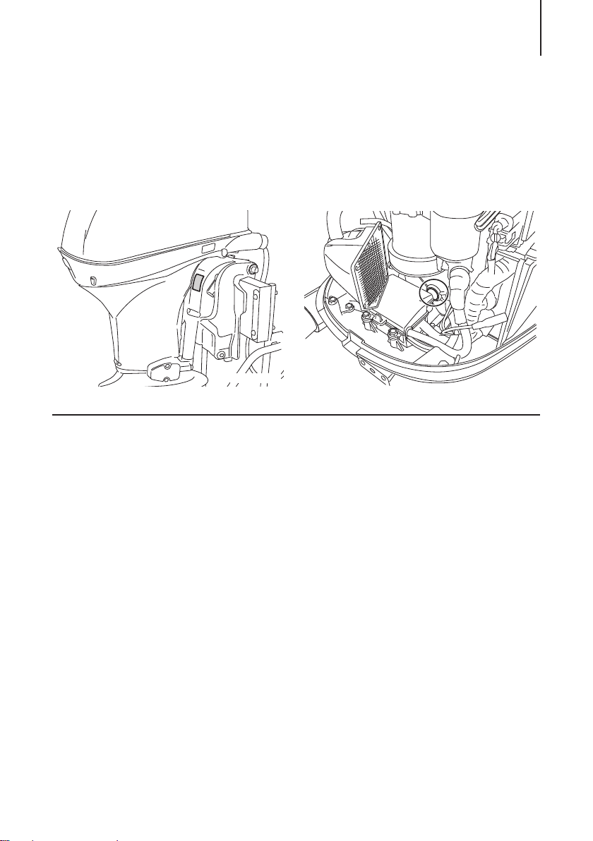
ENOM00005-A
ENOF00800-1
ENOF00801-0
Serial Number
In the space below, please record the outboard motor's serial number (indicated
both on the swivel bracket and on the cylinder block). The serial number will be
needed when ordering parts, and when making technical or warranty inquiries.
Serial Number:
Serial Number: Date of purchase:
5
6
ENOM00007-0
NOTICE: DANGER/WARNING/CAUTION/Note
Before installing, operating or otherwise handling your outboard motor, be sure to
thoroughly read and understand this Owner's Manual and carefully follow all of the
instructions. Of particular importance is information preceded by the words “DANGER,” “WARNING,” “CAUTION,” and “Note.” Always pay special attention to such
information to ensure safe operation of the outboard motor at all times.
ENOW00001-0
DANGER
Failure to observe will result in severe personal injury or death, and possibly property damage.
ENOW00002-0
WARNING
Failure to observe could result in severe personal injury or death, or property damage.
ENOW00003-0
CAUTION
Failure to observe could result in personal injury or property damage.
ENON00001-0
Note
This instruction provides special information to facilitate the use or maintenance of the outboard motor or to clarify important points.

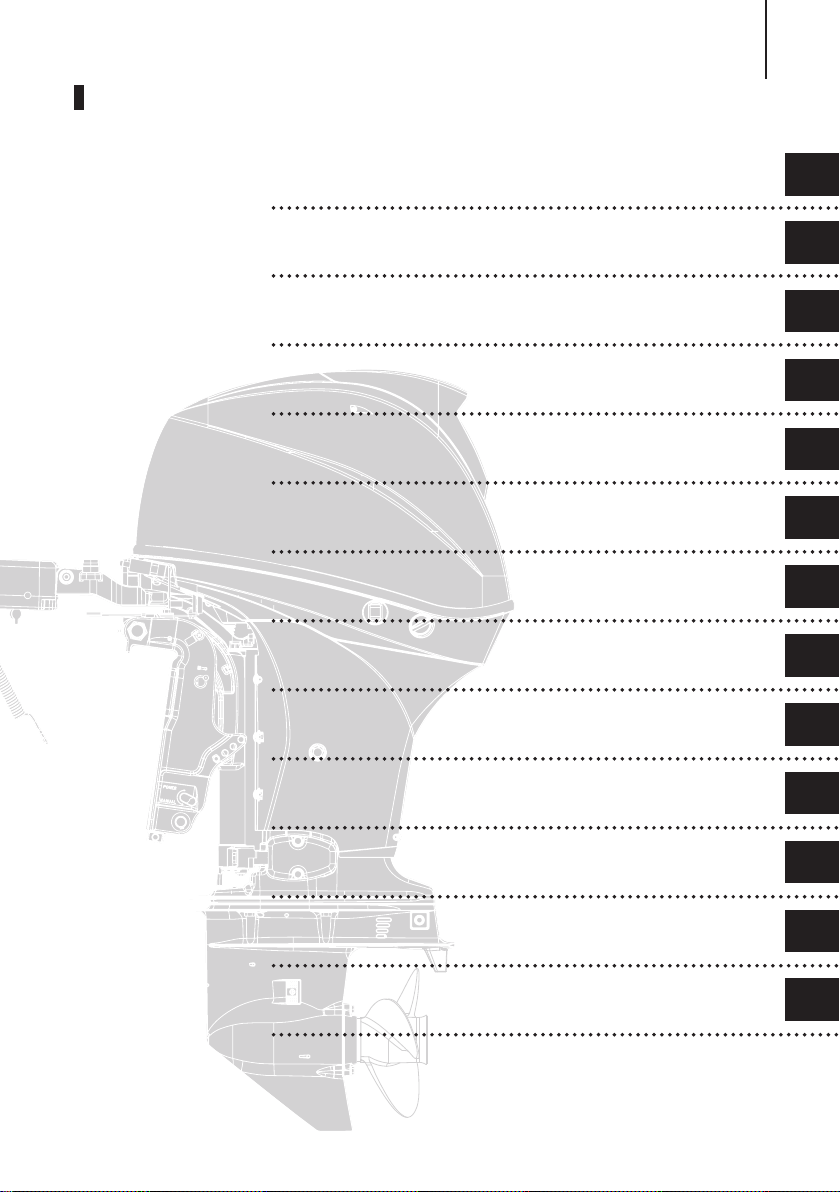
CONTENTS
1. GENERAL SAFETY INFORMATION. . . . . . . . . . . . . . . . . . . . . . . . . . . . . . . . . . . .10
2. SPECIFICATIONS . . . . . . . . . . . . . . . . . . . . . . . . . . . . . . . . . . . . . . . . . . . . . . . . .12
3. PARTS NAME . . . . . . . . . . . . . . . . . . . . . . . . . . . . . . . . . . . . . . . . . . . . . . . . . . . . 15
4. LABEL LOCATIONS . . . . . . . . . . . . . . . . . . . . . . . . . . . . . . . . . . . . . . . . . . . . . . . 17
5. INSTALLATION . . . . . . . . . . . . . . . . . . . . . . . . . . . . . . . . . . . . . . . . . . . . . . . . . . . 21
1. Mounting the outboard motor on boat . . . . . . . . . . . . . . . . . . . . . . . . . . . . 21
2. Remote control device installation . . . . . . . . . . . . . . . . . . . . . . . . . . . . . . 23
3. Battery installation. . . . . . . . . . . . . . . . . . . . . . . . . . . . . . . . . . . . . . . . . . . . 24
4. Propeller installation . . . . . . . . . . . . . . . . . . . . . . . . . . . . . . . . . . . . . . . . . . 25
5. TOCS (Tohatsu Onboard Communication System) installation. . . . . . . . . 26
6. PRE-OPERATING PREPARATIONS . . . . . . . . . . . . . . . . . . . . . . . . . . . . . . . . . . .27
1. Fuel handling . . . . . . . . . . . . . . . . . . . . . . . . . . . . . . . . . . . . . . . . . . . . . . . . .27
2. Fuel filling . . . . . . . . . . . . . . . . . . . . . . . . . . . . . . . . . . . . . . . . . . . . . . . . . . 28
3. Engine oil recommendation . . . . . . . . . . . . . . . . . . . . . . . . . . . . . . . . . . . . 29
4. Break-In . . . . . . . . . . . . . . . . . . . . . . . . . . . . . . . . . . . . . . . . . . . . . . . . . . . . 30
5. Warning system . . . . . . . . . . . . . . . . . . . . . . . . . . . . . . . . . . . . . . . . . . . . . . . 31
7. ENGINE OPERATION . . . . . . . . . . . . . . . . . . . . . . . . . . . . . . . . . . . . . . . . . . . . . 35
Before starting . . . . . . . . . . . . . . . . . . . . . . . . . . . . . . . . . . . . . . . . . . . . . . . . . 35
1. Fuel feeding . . . . . . . . . . . . . . . . . . . . . . . . . . . . . . . . . . . . . . . . . . . . . . . . 36
2. Starting the engine . . . . . . . . . . . . . . . . . . . . . . . . . . . . . . . . . . . . . . . . . . . 42
3. Warming up the engine . . . . . . . . . . . . . . . . . . . . . . . . . . . . . . . . . . . . . . . 43
4. Forward, reverse, and acceleration . . . . . . . . . . . . . . . . . . . . . . . . . . . . . . 43
5. Stopping the engine . . . . . . . . . . . . . . . . . . . . . . . . . . . . . . . . . . . . . . . . . . 47
6. Steering . . . . . . . . . . . . . . . . . . . . . . . . . . . . . . . . . . . . . . . . . . . . . . . . . . . . 49
7. Trim angle . . . . . . . . . . . . . . . . . . . . . . . . . . . . . . . . . . . . . . . . . . . . . . . . . . 50
8. Tilt up and down . . . . . . . . . . . . . . . . . . . . . . . . . . . . . . . . . . . . . . . . . . . . . . 51
9. Shallow water operation . . . . . . . . . . . . . . . . . . . . . . . . . . . . . . . . . . . . . . . 54
8. REMOVING AND CARRYING THE OUTBOARD MOTOR. . . . . . . . . . . . . . . . . . . 56
1. Removing the outboard motor . . . . . . . . . . . . . . . . . . . . . . . . . . . . . . . . . . 56
2. Carrying the outboard motor . . . . . . . . . . . . . . . . . . . . . . . . . . . . . . . . . . . 56
3. Trailering . . . . . . . . . . . . . . . . . . . . . . . . . . . . . . . . . . . . . . . . . . . . . . . . . . . .57
9. ADJUSTMENT. . . . . . . . . . . . . . . . . . . . . . . . . . . . . . . . . . . . . . . . . . . . . . . . . . . 59
1. Steering friction . . . . . . . . . . . . . . . . . . . . . . . . . . . . . . . . . . . . . . . . . . . . . 59
2. Throttle grip friction . . . . . . . . . . . . . . . . . . . . . . . . . . . . . . . . . . . . . . . . . . 59
3. Remote control lever friction . . . . . . . . . . . . . . . . . . . . . . . . . . . . . . . . . . 59
4. Trim tab adjustment . . . . . . . . . . . . . . . . . . . . . . . . . . . . . . . . . . . . . . . . . . 60
10. INSPECTION AND MAINTENANCE. . . . . . . . . . . . . . . . . . . . . . . . . . . . . . . . . . . . 61
1. Daily Inspection . . . . . . . . . . . . . . . . . . . . . . . . . . . . . . . . . . . . . . . . . . . . . . 62
2. Periodic Inspection . . . . . . . . . . . . . . . . . . . . . . . . . . . . . . . . . . . . . . . . . . . .67
3. Off-season storage . . . . . . . . . . . . . . . . . . . . . . . . . . . . . . . . . . . . . . . . . . . .79
4. Pre-season check . . . . . . . . . . . . . . . . . . . . . . . . . . . . . . . . . . . . . . . . . . . . 82
5. Submerged outboard motor . . . . . . . . . . . . . . . . . . . . . . . . . . . . . . . . . . . . 82
6. Cold weather precautions. . . . . . . . . . . . . . . . . . . . . . . . . . . . . . . . . . . . . . 83

7. Striking underwater object . . . . . . . . . . . . . . . . . . . . . . . . . . . . . . . . . . . . . 83
8. Operation with multiple outboard motors . . . . . . . . . . . . . . . . . . . . . . . . 83
11. TROUBLESHOOTING. . . . . . . . . . . . . . . . . . . . . . . . . . . . . . . . . . . . . . . . . . . . . 84
12. ACCESSORIES KIT . . . . . . . . . . . . . . . . . . . . . . . . . . . . . . . . . . . . . . . . . . . . . . . 86
13. PROPELLER TABLE . . . . . . . . . . . . . . . . . . . . . . . . . . . . . . . . . . . . . . . . . . . . . . 87
INDEX
9
1 GENERAL SAFETY INFORMATION
2 SPECIFICATIONS
3PARTS NAME
4 LABEL LOCATIONS
5INSTALLATION
6 PRE-OPERATING PREPARATIONS
7 ENGINE OPERATION
8 REMOVING AND CARRYING THE OUTBOARD
MOTOR
9 ADJUSTMENT
1
2
3
4
5
6
7
8
9
10 INSPECTION AND MAINTENANCE
11 TROUBLESHOOTING
12 ACCESSORIES KIT
13 PROPELLER TABLE
10
11
12
13
1
1
10
GENERAL SAFETY INFORMATION
ENOM00009-0
SAFE OPERATION OF BOAT
1
As the operator/driver of the boat, you are responsible for the safety of those aboard
and those in other boat around yours, and for following local boating regulations. You
should be thoroughly knowledgeable on how to correctly operate the boat, outboard
motor, and accessories. To learn about the correct operation and maintenance of the
outboard motor, please read through this manual carefully.
It is very difficult for a person standing or floating in the water to take evasive action
should he or she see a power boat heading in his/her direction, even at a slow speed.
Therefore, when your boat is in the immediate vicinity of people in the water, the
outboard motor should be shifted to neutral and shut off.
ENOW00005-0
WARNING
SERIOUS INJURY IS LIKELY IF A PERSON IN THE WATER MAKES CONTACT WITH A MOVING
BOAT, GEAR HOUSING, PROPELLER, OR ANY SOLID DEVICE RIGIDLY ATTACHED TO A BOAT OR
GEAR HOUSING.
ENOM0008-A
EMERGENCY STOP SWITCH
The Emergency Stop Switch will stall the outboard motor when the stop switch lanyard is pulled off. This stop switch lanyard has to be attached to the operator of the
outboard motor to minimize or prevent injuries from the propeller in case the operator falls overboard.
It is operator’s responsibility to use the Emergency Stop Switch Lanyard.
ENOW00004-A
WARNING
Accidental activation of the Emergency Stop Switch (such as the tether being pulled out in
heavy seas) could cause passengers to lose their balance and even fall overboard, or it could
result in loss of power in heavy seas, strong currents, or high winds. Loss of control while
mooring is another potential hazard.
To minimize accidental activation of the Emergency Stop Switch, the 500 mm (20 in.) stop
switch lanyard is coiled and can extended to a full 1300 mm (51 in.).
ENOM00800- A
PERSONAL FLOATATION DEVICE
As the operator/driver and passenger of the boat, you are responsible to wear a PFD
(Personal Flotation Device) while on the boat.

GENERAL SAFETY INFORMATION 11
ENOM00010-0
SERVICING, REPLACEMENT PARTS & LUBRICANTS
We recommend that only an authorized service shop perform service or maintenance
on this outboard motor. Be sure to use genuine parts, genuine lubricants, or recommended lubricants.
ENOM00011-A
MAINTENANCE
As the owner of this outboard motor, you should be acquainted with correct maintenance procedures following maintenance section of this manual (See page 61). It is
the operator's responsibility to perform all safety checks and to ensure that all lubrication and maintenance instructions are complied with for safe operation. Please
comply with all instructions concerning lubrication and maintenance. You should take
the engine to an authorized dealer or service shop for periodic inspection at the prescribed intervals.
Correct periodic maintenance and proper care of this outboard motor will reduce
the chance of problems and limit overall operating expenses.
Carbon Monoxide Poisoning Hazard
Exhaust gas contains carbon monoxide, a colorless and odorless gas which can be
fatal if inhaled for any length of time.
Never start or operate the engine indoors or in any space which is not well ventilated.
1
Gasoline
Gasoline and its vapors are very flammable and can be explosive. Use extreme care
when handling gasoline. You should be thoroughly knowledgeable on how to correctly
handle gasoline by reading this manual.

12
SPECIFICATIONS
ENOM00810- A
MODEL FEATURE
2
Typ e ET EG ET EG
Model F40 A F50A
Transom heights
Tiller Handle (z) z (z) z
Remote Control (z) (z)
Power Trim & Tilt z z
Gas-assisted tilt z z
(z) These models can be purchased with remote rigging kit or multi function tiller han-
S z z z z
L z z z z
dle.
ENOM00811-A
MODEL NAME EXAMPLE
F 50A ETL
F 50 A E T L
Model
description
F= Four stroke
D= Two stroke DI
Horse power
- A and up
Product gen-
eration
Starter
system
E= Electrical start
Blank= Manual star t
Tilt system Shaft length
T= Po wer trim& tilt
G= Gas assist
Blank= Manual tilt
S= Short 15 in
L= Long 20 in
UL= Ultra long 25 in
ENOM00013-0
ET, EG
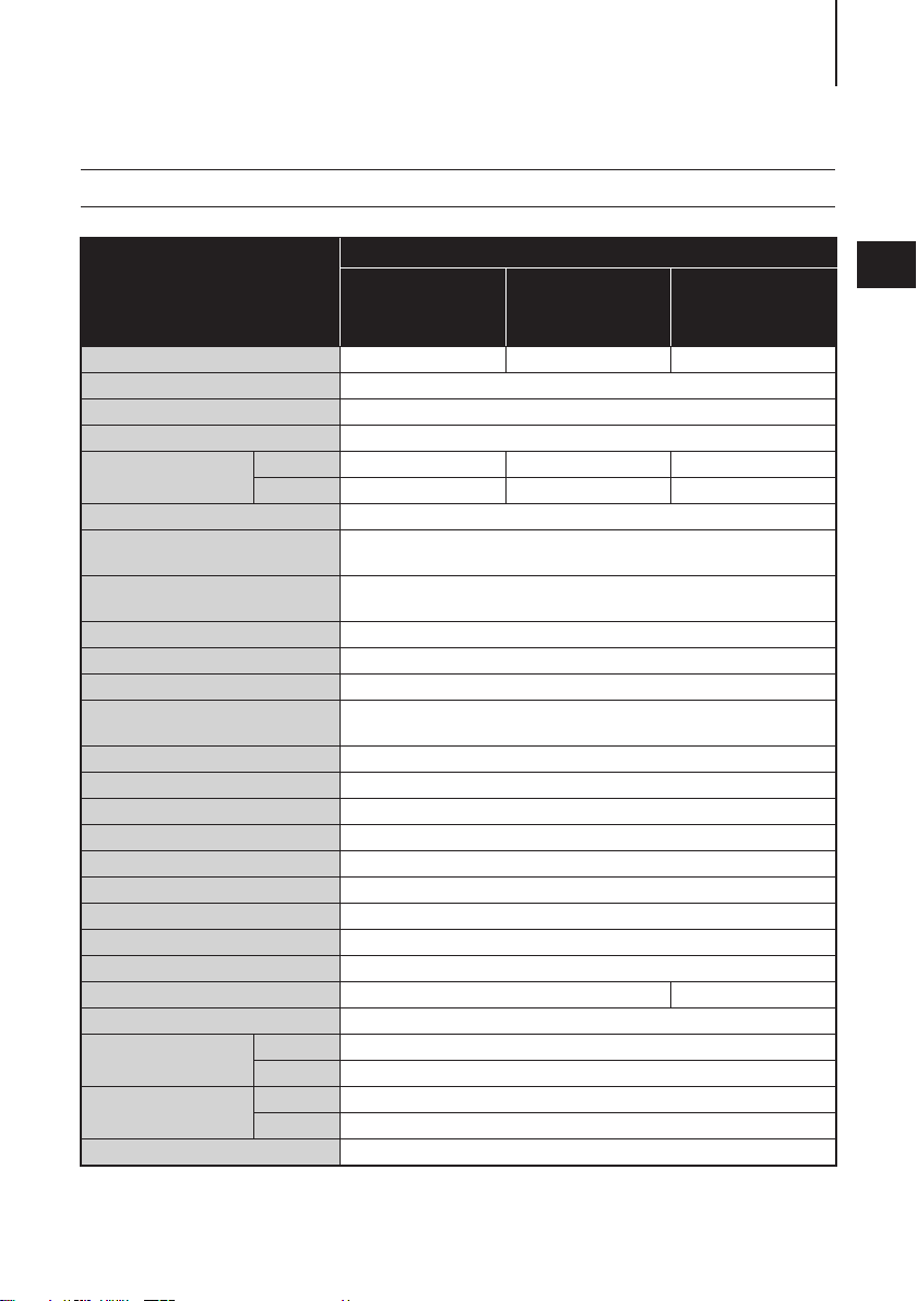
SPECIFICATIONS 13
F40A/50A
Item MODEL
ET
(with RC)
Overall Length mm (in) 783 (30.8) 1382 (54.4) 1382 (54.4)
Overall Width mm (in) 404 (15.9)
Overall Height S·L mm (in) 1257 (49.5) 1390 (54.7)
Transom Height S·L mm (in) 405 (15.9) 538 (21.2)
Weig ht*
Max. Output kW (ps) 40A : 29.4 (40) 50A : 36.8 (50)
Max. Operating Range
Idle Speed
Engine Type 4-Stroke fuel injection
Number of Cylinder 3
Bore × Stroke mm (in) 70 × 75 (2.76 × 2.96)
Piston Displacement
Exhaust System Through hub exhaust
Cooling System Water cooling (with thermostat)
Lubrication System Wet sump (Trochoid pump)
Starting System Electric starter motor
Ignition System Battery ignition
Spark Plug NGK IKR6G8
Alternator 12V 252W (21A)
Trim position 4
Trim angle Degree 8-20
Tilt up angle Degree 74 68
Steering angle Degree 70
Engine Oil
Gear Oil
Fuel Unleaded Regular Gasoline : R+M/2: 87 or higher RON: 91 or higher
S kg (lb) 95 (209) 100 (220) 97.5 (215)
L kg (lb) 97 (214) 102 (225) 99.5 (219)
-1
min
(rpm)
-1
min
(rpm)
cm3 (Cu
in)
Grade API standard SH, SJ, SL, SAE 10W-30/40
mL(US qt) 2200 (2.3)
Grade Genuine Gear Oil or API GL5, SAE #80-90
mL(US qt) 500 (0.53)
ET (with
multifunction
tiller handle)
5000–6000
850
866 (52.8)
EG (with
multifunction
tiller handle)
2
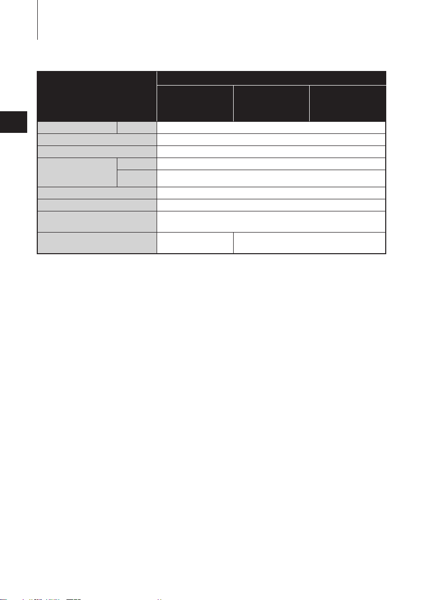
SPECIFICATIONS14
Item MODEL
2
Fuel Tank Capacit y L (US gal) 25 (6.60)
Gear shift Dog clutch ( F-N-R)
Gear Reduction Ratio 2.08 (13:27)
Battery
Ta c h o m e t e r P o l e S e t t i n g 4
Emission Control System MFI (Multiport Fuel Injection)
Operator Sound Pressure
(ICOMIA 39/94 Rev.1) dB (A)
Hand Vibration Level
(ICOMIA 38/94 Rev.1) m/s
Remark: Specifications subject to change without notice.
*Without propeller, with battery cable.
Tohatsu outboard is power rated in accordance with ISO8665 (propeller shaft output).
Cold weather
specification
2
ET
(with RC)
–2.9
multifunction
tiller handle)
12V 100Ah/5HR, 850 CCA
12V 120Ah/5HR, 1000 CCA
F40A/50A
ET (with
81.8
EG (with
multifunction
tiller handle)
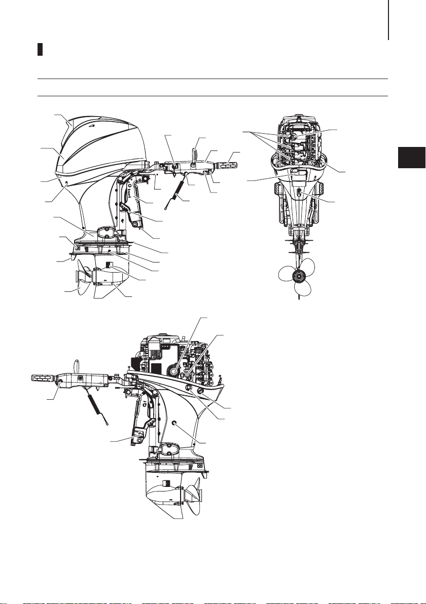
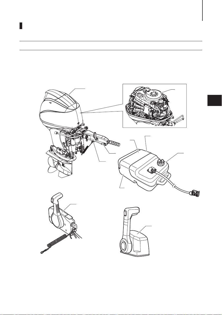
PARTS NAME
ENOM00820-0
ET, EG (with multi-function tiller handle)
1
18
2
3
17
4
5
6
16
15
14
13
7
12
11
10
8
9
37
31
25
24
19
20
22
23
32
33
35
36
27
34
21
29
1
2
3
4
5
6
7
8
9
10
11
12
13
14
15
16
17
18
19
Tilt Handle
Top Cowl
Bottom Cowl
Cooling Water
Check Port
Drive Shaft
Housing
Anode
Trim Tab
Propeller
Oil Plug (Lower)
Cooling Water
Inlet
Oil Plug (Upper)
Anti- ventilation
Plate
Splash Plate
Anode
Thrust Rod
Clamp Bracket
Steering Friction
Lever
Main Switch Key
Shift Lever
26
28
30
20
Tiller Handle
21
Throttle Grip
22
PTT Switch
23
Warning Lamp
24
Stop Switch
25
Stop Switch
Lanyard
26
Oil Filler Cap
27
Spark Plug
28
Oil Level Gauge
29
Cowl Hook Lever
30
Idle Port
31
Manual Valve*
32
Oil Filter
33
Fuel Filter
34
Flushing
Connector Cap
35
PTT Switch*
36
Oil Drain Bolt
37
Throttle Friction
Screw
*: Only for ET model
15
3
ENOF00820-A
PARTS NAME16
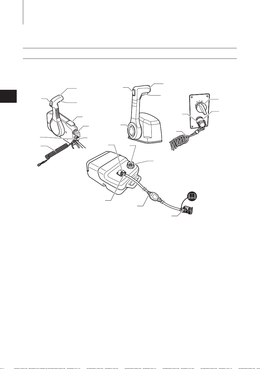
ENOM00822-0
Remote control box & Fuel tank
3
3
7
8
1
Control Lever
2
Neutral lock arm
3
PTT switch
4
Free throttle lever
5
Main switch
6
Stop switch
7
Stop switch lock
8
Stop switch lanyard
9
Control lever
10
Neutral lock arm
10
9
13
15
14
16
1
11
2
4
5
12
6
17
18
19
22
21
ENOF00127-6
11
PTT switch
12
Neutral throttle button
13
Main switch
14
Stop switch
15
Stop switch lock
16
Stop switch lanyard
17
Fuel gauge
18
Air vent screw
19
Fuel tank cap
20
Fuel connector (Engine side)
20
21
Primer bulb
22
Fuel connector (Fuel tank
side)
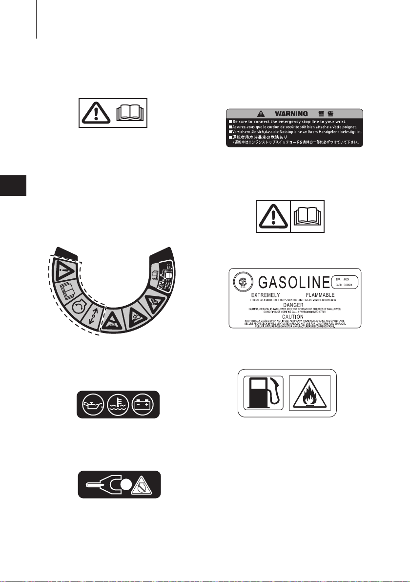
LABEL LOCATIONS
ENOM00019-A
Warning label locations
17
1
2
4
7
3
4
10
5
8
9
6
ENOF00127-D1
LABEL LOCATIONS18
ENOF00120-0
1
2
3
4
5
3KZX72181-1
ENOF00005-C
ENOF00120-0
ENOF00005-L
1.
Warning label urge to read the
owner’s manual .
2-1. Warning regarding emergency
starting (See page 40).
2-2. Warning regarding high tempera-
4
ture.
2-3. Warning regarding rotating object.
2-4. Warning regarding high voltage
2-5. Caution label regarding fuel filter.
(See page 62, 67, 68
For tiller handle model
3.
Indicator label regarding engine failure/ malfunction (See page 32).
For RC model
5.
Warning label regarding stop switch
lanyard.
ENOF00005-D
For Top mount RC
6.
Warning label urge to read the
owner's manual.
7.
Warning regarding gasoline.
ENOF00005-E
8.
Warning regarding gasoline (See
page 27).
For tiller handle model
4. Warning label regarding stop switch
(See page 37 and page 38)
ENOF00005-P
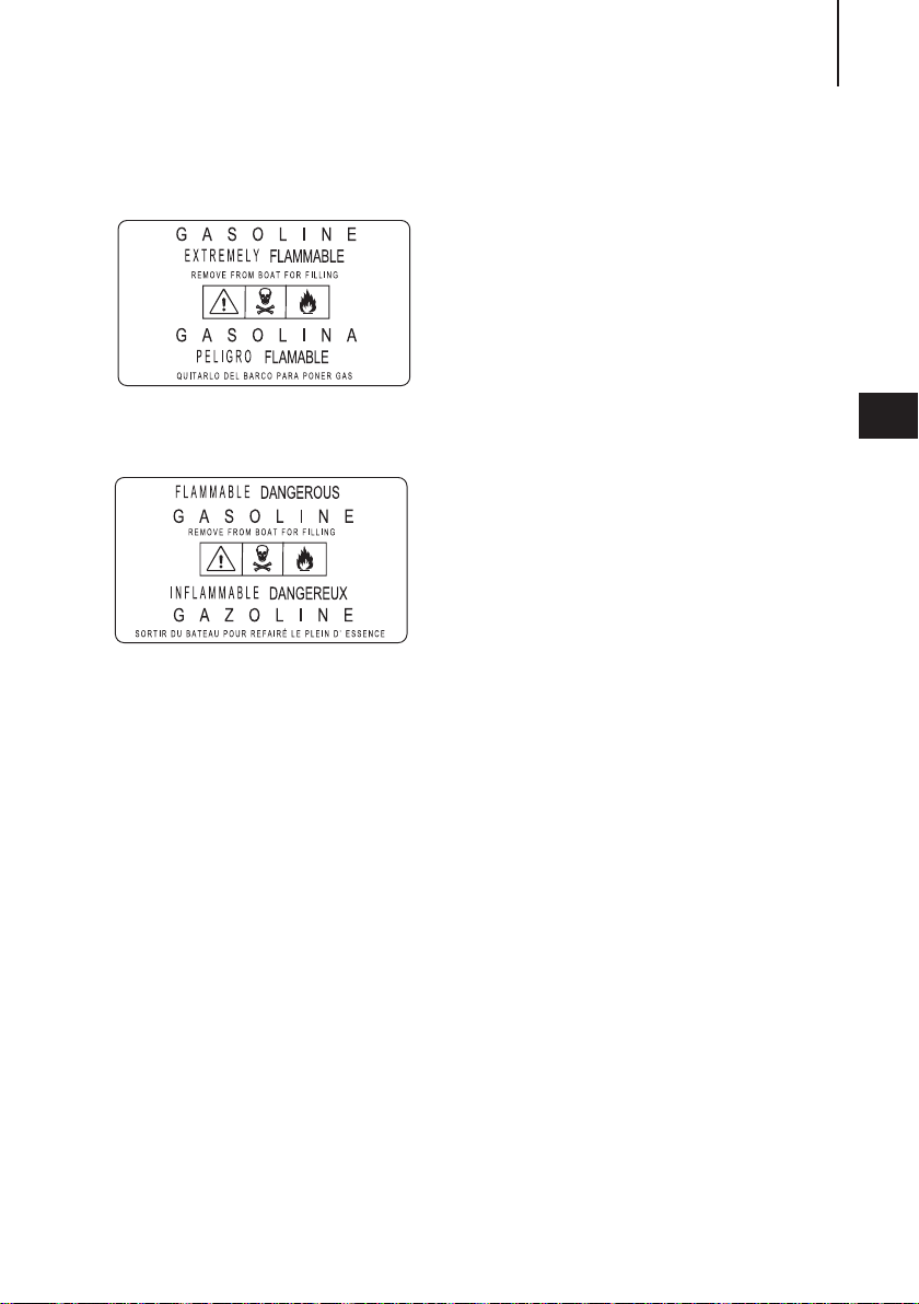
9.
Warning regarding gasoline (See
page 27).
LABEL LOCATIONS 19
10.
Warning regarding gasoline (See
ENOF00005-M
page 27).
ENOF00005-F
4
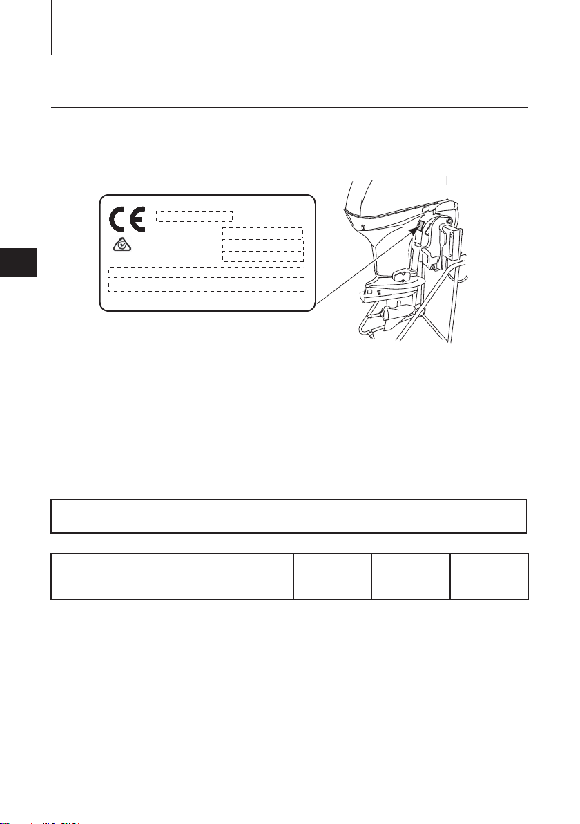
LABEL LOCATIONS20
CE label locations
ENOM00019-B
a R
0123
4
: s s a M
l a i r e S
a M
1. Model code (Model name)
2. Rated power
3. Dr y mass weight (Without propeller, with battery
cable)
4. Serial No.
5. Manufacturer name
6. Manufacturer address
Description of serial number year code
Last two digits of alphabet represent production year as below.
Year Code AG AH AK BX BA
Year of
manufacture
2017 2018 2019 2020 2021
r o t o M d r a o b t u O
: r e w o P d e t
1)
2)
3)
. o N
4)
5)
6)
n a p a J
i
n
e d
CAN ICE S-2/NMB-2
ENOF00005-N
INSTALLATION
ENOF00840-0
21
ENOM00024-A
1. Mounting the outboard
motor on boat
ENOW00006-C
WARNING
Gas assist type:
z When taking outboard motor from pack-
age or removing outboard motor from the
boat, never release the lock lever. If the
lock lever is released, it will very easy for
the clamp bracket to spring up to the tilting direction because it is not fixed.
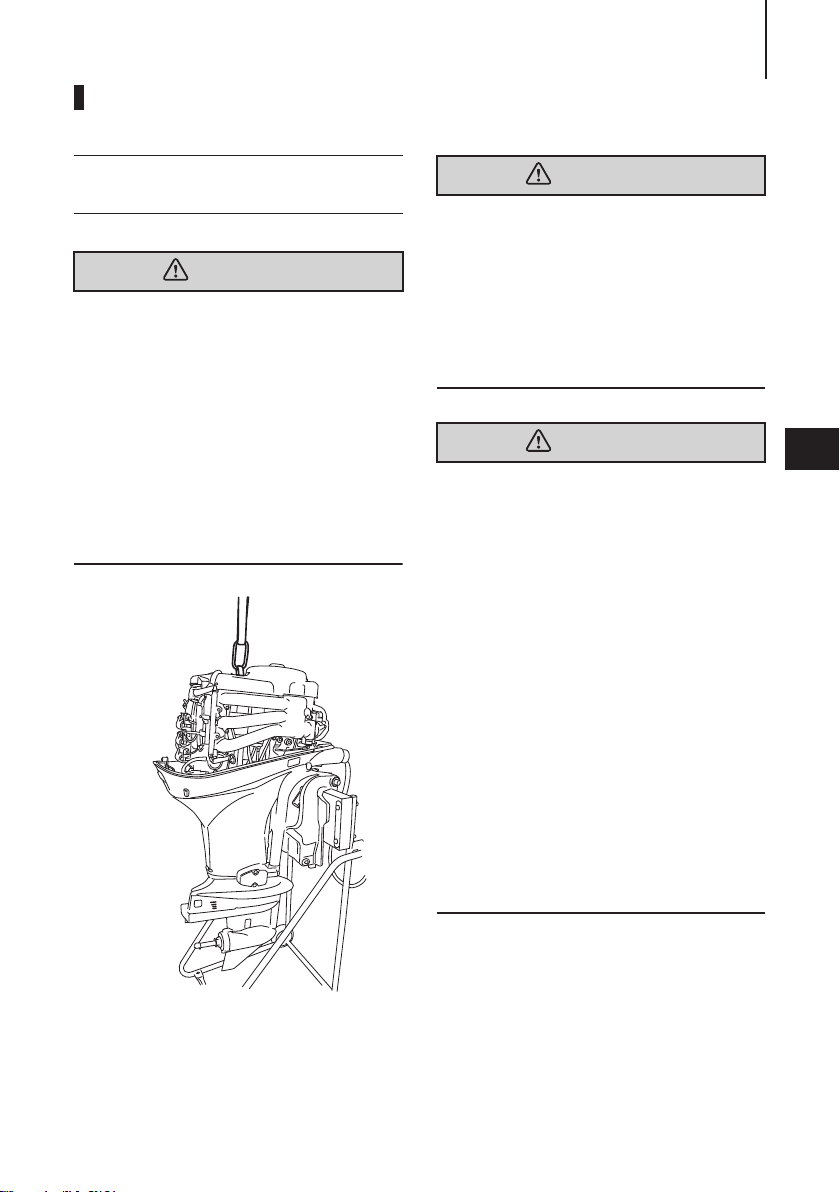
z Before installing the outboard motor on
the boat, hang the outboard motor with
the hoist or equivalent device by attaching the engine hanger to the outboard.
Use the hoist with allowable load is 250 kg
(550 lbs) or above.
ENOW00006-0
WARNING
Most boats are rated and certified in terms
of their maximum allowable horsepower, as
shown on the boat’s certification plate. Do
not equip your boat with an outboard motor
that exceeds this limit. If in doubt, contact
your dealer.
Do not operate the outboard motor until it
has been securely mounted on the boat in
accordance with the instructions below.
ENOW00009-0
WARNING
z Mounting the outboard motor without
following this manual can lead to unsafe
conditions such as poor maneuverability,
lack of control or fire.
z Loose clamp screws and/or mounting
bolts can lead to the release or displacement of the outboard motor, possibly
resulting in lost of control and/or serious
personal injury. Be sure that fasteners are
tightened to the specified torque (30 N·m
(3.0 kgf·m) 13 ft·lb). Check the fasteners
for tightness from time to time.
z Be sure to use outboard mounting fasten-
ers included in the outboard motor package or their equivalents in terms of size,
material, quality and strength. Tighten
fasteners to the specified torque (30 N·m
(3.0 kgf·m) 13 ft·lb). Test cruise to check
if fasteners are tightened securely.
z Outboard motor mounting must be per-
formed by trained service person(s) using
lift or hoist with sufficient capacity.
5
Outboard motor mounting must be performed by trained service person(s)
using lift or hoist with sufficient capacity.
INSTALLATION22
1
2
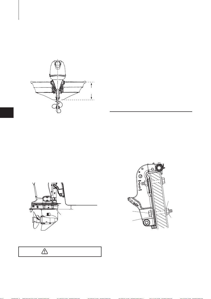
10−30 mm
(0.4−1.2 in)
ENOF00015-A
ENOM00025-0
Position ... Above keel line
Set engine at center of boat.
1
5
1. Center of boat
2. Boat transom
ENOM00026-0
Transom matching
Be sure that the anti ventilation plate of
the outboard motor is 10–30 mm (0.4–
1.2 in) below the bottom of hull.
If the above condition cannot be met
due to the shape of the bottom of your
boat, please consult your authorized
dealer.
2
ENOF01141-0
attitude. Check the position of water surface on the driveshaft housing. If the
water surface is near the bottom cowling,
in high waves, water may enter the engine
cylinders.
z Incorrect outboard motor mounting
height or existence of underwater
object(s), such as hull bottom design,
bottom surface conditions or underwater accessories, can cause water spray
possibly reaching the engine through an
opening of the bottom cowling during
cruising. Exposing the engine to such
conditions for extended periods can lead
to severe engine damage.
ENOM00830 -B
Mounting bolts
1. To attach the outboard motor to the
boat, use the bolts to secure the
outboard motor brackets on transom
board.
1. Bottom of hull
2. Anti ventilation plate
ENOW00007-0
CAUTION
z Before beginning the running test, check
that the boat with maximum capacity
loading floats on the water in a proper
1
2
1. Bolt (12 × 105)
2. Washer (small diameter)
3. Nut
4. Washer (large diameter)
4
3
ENOF00017-A
INSTALLATION 23
3
1, 2
ENOF00841-1
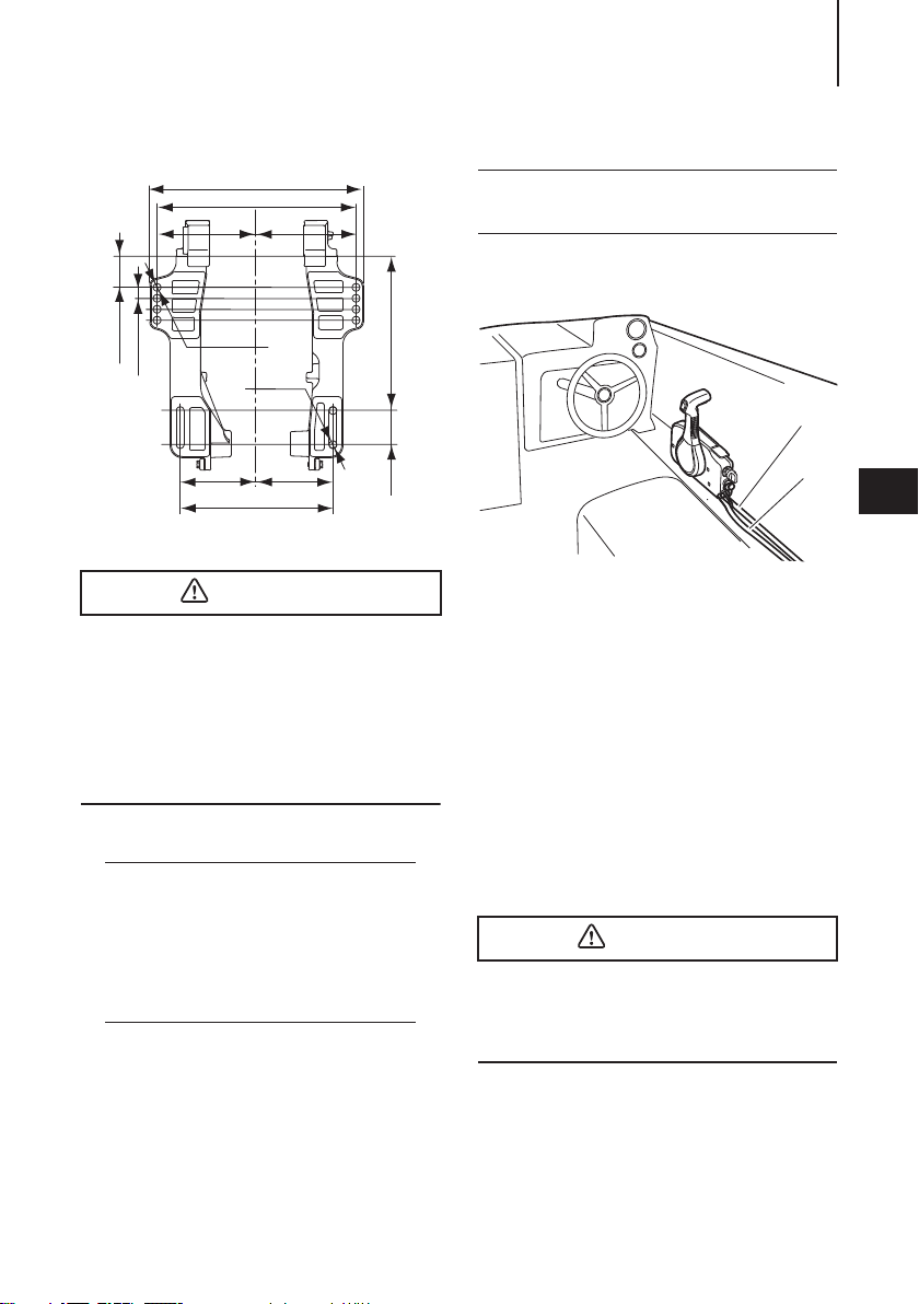
351 (13.82)
327 (12.87)
163.5 163.5
51 (2.01)
18 (0.17)
ENOW00008-A
Ø12.5
125.5
251 (9.88)
Ø12.5
125.5
253.5 (9.98)
56
(2.2)
ENOF00018-A
CAUTION
z Mounting bolts should be installed with
the bolt head at inside surface of the
transom. Mounting bolts installed with
the threaded end at the inside surface of
the transom can cause personal injury.
z Tighten the bolts sufficiency, otherwise
falling down of outboard could be happened.
ENON00003-0
Notes
1. Apply sealing agent, such as silicone
sealed between the bolts and the
transom board holes before tightening the bolts.
2. Be sure to tighten the mounting bolt
nuts to the specified torque.
(30 N·m (3.0 kgf·m) 13 ft·lb)
ENOM0084 0-0
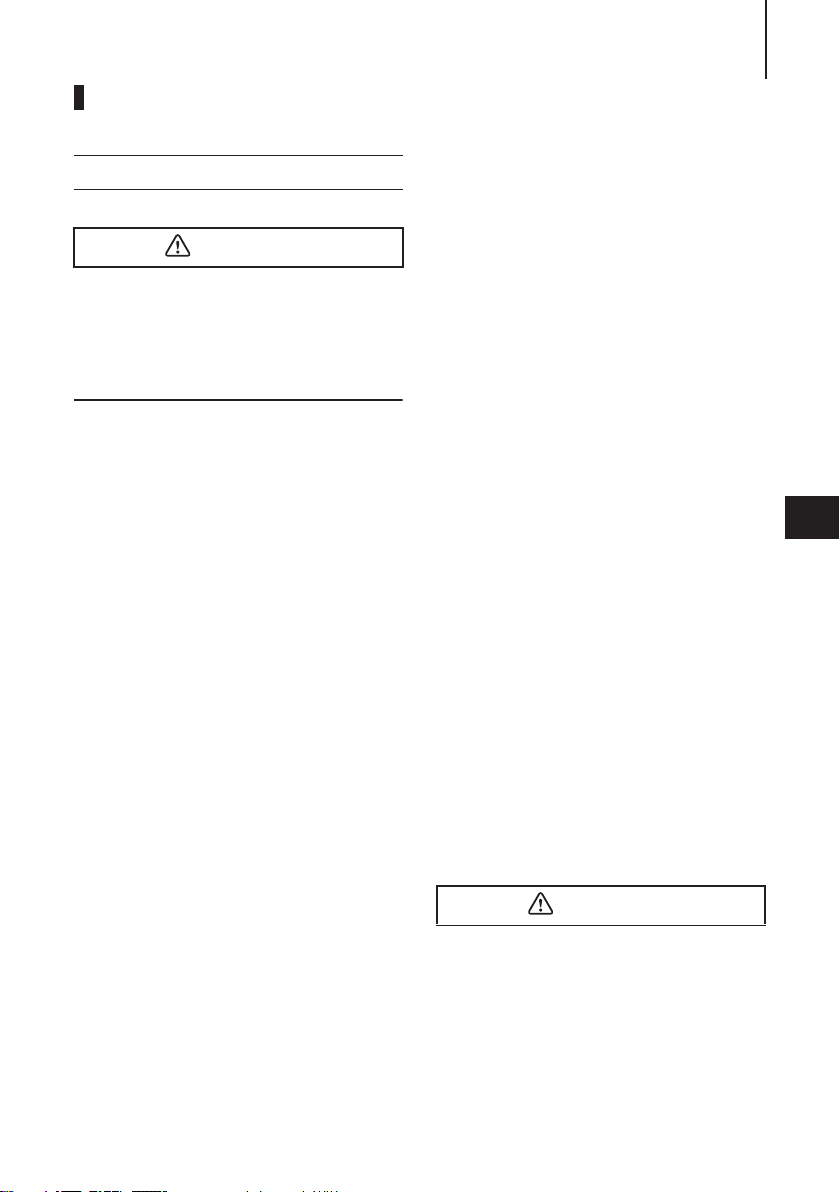
2. Remote control device
installation
ENOW0085 0-0
Remote control box location
1. Shift cable
2. Throttle cable
3. Cable harness B
Install the remote control box in a position where it is easy to reach and operate the controls.
Make sure there are no obstacles that
can interfere with the operation of the
remote control cable.
ENOW0085 0-0
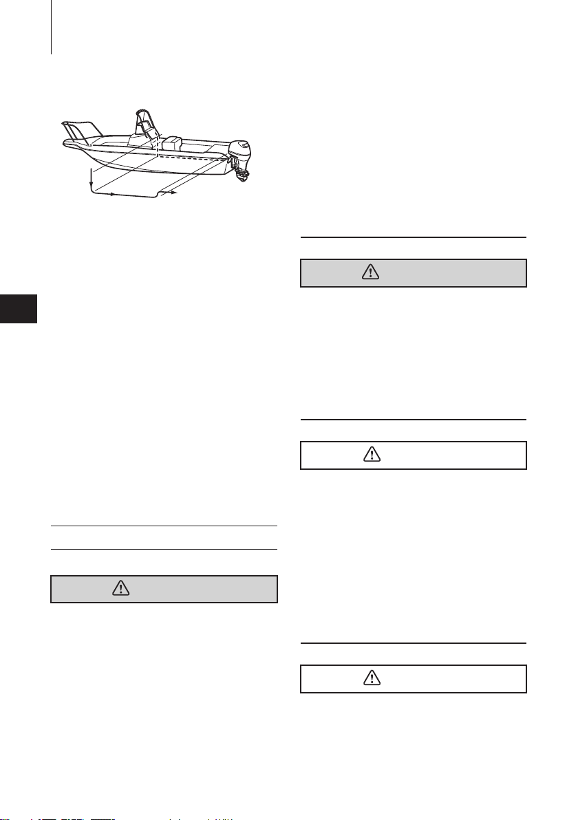
Remote control cable length
ENOW00100-A
CAUTION
Be careful not to loop the remote control
cables to a diameter of 406 mm (16 in) or
less. Otherwise, it affects the service life of
the cable.
5
INSTALLATION24
can cause serious burn or, if it comes in
contact with your eye, loss of sight. Use
safety glasses and rubber gloves.
In case battery electrolyte comes in contact
with:
z Skin, flush thoroughly with water.
z Eye, flush thoroughly with water, and
then seek immediate medical treatment.
ENOF00842-0
In case battery electrolyte is swallowed:
z Seek immediate medical treatment.
Measure the distance from the remote
control box to the outboard motor
where the remote control cable should
be routed.
5
Prepare a cable that is 300-450mm
(11.8-17.7in) longer than the measured
distance.
Temporarily pull the cable along the
intended cable route to check its length
is sufficient.
Connect the remote control cable to the
engine, then run the cable to the remote
control box, making sure it is not sharply
bent, too taut and free from obstructions that could interfere with steering.
ENOM00029-A
3. Battery installation
ENOW00012-0
WARNING
Battery electrolyte contains sulfuric acid
and thus is hazardous, causing a burn if it
comes in contact with your skin, or poisonous if swallowed.
Keep battery and electrolyte away from
reach of children
When handling the battery, be sure to:
z Read all warnings shown on the battery
case
z Prevent electrolyte from coming in con-
tact with any part of your body. Contact
ENOW00013-B
WARNING
Battery generates explosive hydrogen gas.
Be sure to:
z Charge the battery in a well-ventilated
place.
z Place the battery away from any source of
fire, sparks and open flames such as
burners or welding equipment.
z Do not smoke near the battery when the
battery is charging.
ENOW00014-0
CAUTION
z Make sure that the battery leads do not
get stuck between the outboard motor
and boat when turning, etc.
z The starter motor may fail to operate if
the leads are incorrectly connected.
z Be sure to correctly connect the (+) and
(—) leads. If not, the charging system will
be damaged.
z Do not disconnect the battery leads from
battery while the engine is operating, the
electrical parts could be damaged.
z Always use a fully charged battery.
ENOW00015-0
CAUTION
Do not use a battery that is not recommended. Use of a battery not recommended
INSTALLATION 25
2
1
ENOF00022-0
can lead to poor performance of, and/or
damage to, the electrical system.
ENON00006-A
Note
Recommended battery: 12V 100Ah/5HR,
850 (Cold Cranking Amps (CCA), In case of
cold whether: 12V120Ah/5HR (1000CCA))
Specifications and features of batteries
vary among the manufacturers. Consult
the manufacturer for details.
* The battery should be purchased separately and is not supplied with the outboard motor.
1. Place the battery box in a convenient
position away from possible water
spray. Securely fasten both the box
and the battery so they do not shake
loose.
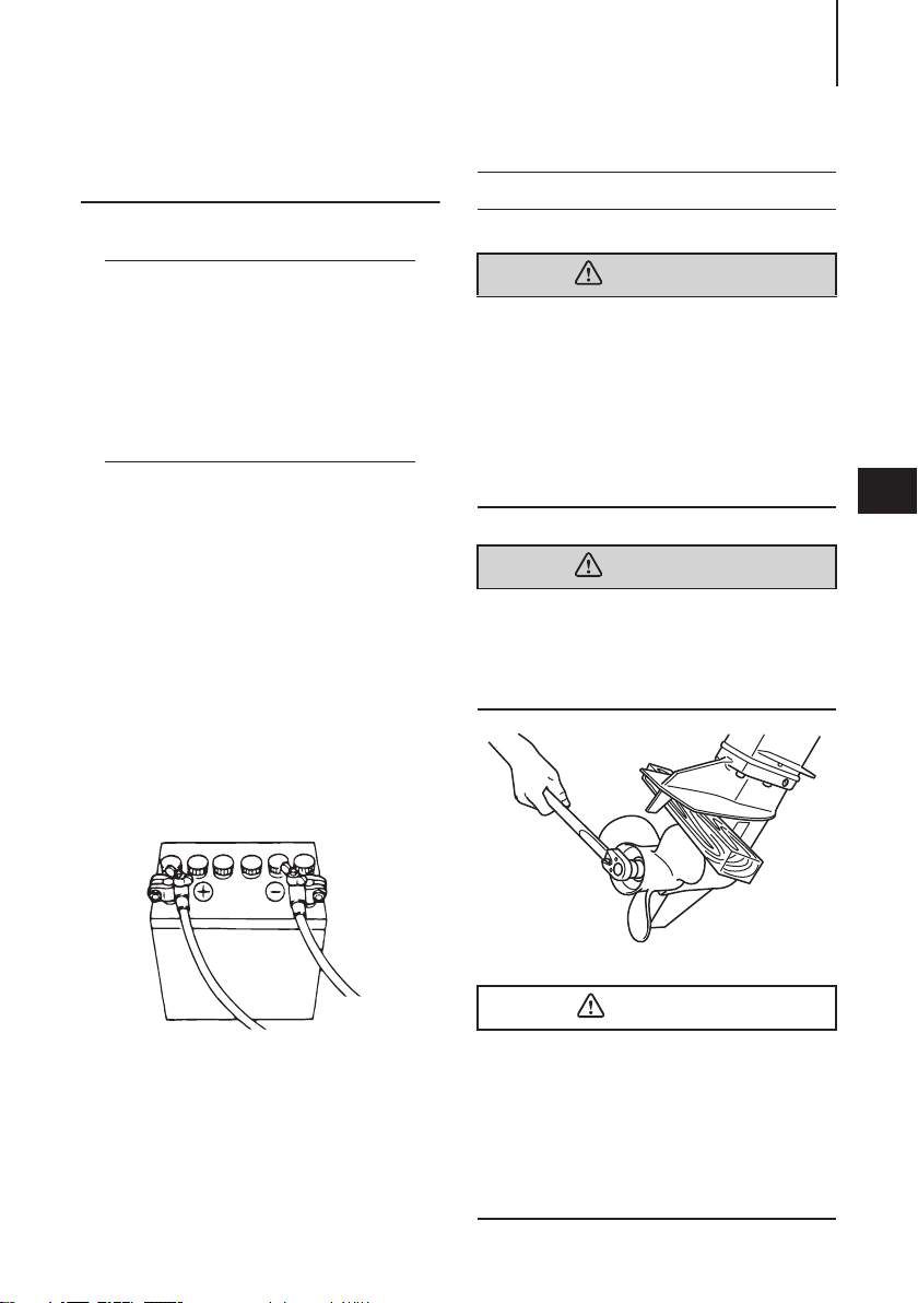
2. Connect the positive lead (+) to the
positive terminal (+) of the battery,
and then connect the negative lead
(—). When disconnecting the battery
always remove the negative lead (—)
first. After connecting the positive
terminal (+), securely place a cap on
it to prevent short circuits.
ENOM00123-0
4. Propeller installation
ENOW00085-A
WARNING
Do not begin propeller removal and installation procedure with spark plug caps
attached, shift in forward or reverse, main
switch at other than “OFF”, engine stop
switch lock attached to the switch, and
starter key attached, or engine could accidentally start leading to serious personal
injury.
Disconnect battery cable if possible.
ENOW00085-0
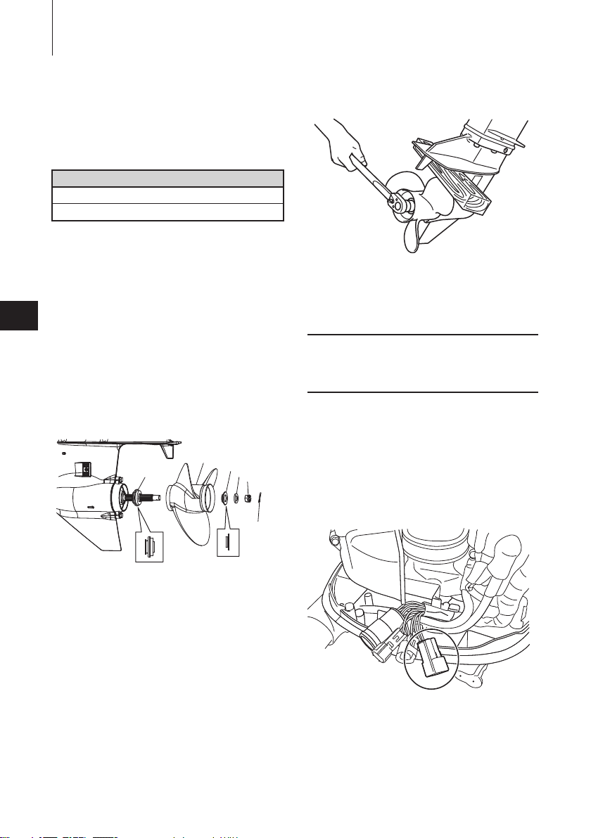
WARNING
Do not hold propeller with hand(s) when
loosening or tightening propeller nut. Put a
piece of wood block between propeller
blade and anti-ventilation plate to hold propeller.
5
1. Battery cord (red)
2. Battery cord (black)
ENOF00084-B
ENOW00086-0
CAUTION
z Do not install propeller without thrust
holder, or propeller boss could be damaged.
z Do not reuse split pin.
z After installing split pin, spread the pin
apart to prevent it from falling out which
could lead to the propeller coming off
during operation.
INSTALLATION26
1
2
3
4
6
5
ENOF00084-A
ENOF00933-0
Propeller must be selected that will
allow the engine to reach recommended
maximum operating range during cruising.
Wide-open throttle rpm range
40/50
5000 – 6000 min
-1
(rpm)
Genuine propellers are listed on PROPELLER TABLE of this manual (See
page 85).
1. Remove the split pin, propeller nut
5
and washer.
2. Apply water proof grease to the propeller shaft before installing a new
propeller.
3. Install the thrust holder, propeller
stopper, washer and propeller nut
onto the shaft.
ENOF00084-B
5. Install a new split pin into the nut
hole and bend it.
ENOM00971 -0
5. TOCS (Tohatsu Onboard
Communication System)
installation
TOCS (Tohatsu Onboard Communication
System) interface coupler can provide
information regarding engine speed,
fuel consumption, and various malfunction via an optional interface cable.
Contact authorized Tohatsu dealer for
more detail.
1. Propeller
2. Thrust holder
3. Stopper
4. Washer
5. Nut
6. Split pin
4. Tighten the propeller nut to specified torque with holding the propeller by wood block. And align one of
grooves to propeller shaft hole.
Propeller nut torque:
35 N·m (25 ft·lb, 3.5kgf·m)
PRE-OPERATING PREPARATIONS
27
ENOM00030-A
1. Fuel handling
ENOW000017-0
CAUTION
Use of improper gasoline can damage your
engine. Engine damage resulting from the
use of improper gasoline is considered misuse of the engine, and damage caused
thereby will not be covered under the limited warranty.
ENOM00031-A
FUEL RATING
TOHATSU engines will operate satisfactorily when using a major brand of
unleaded gasoline meeting the following
specifications:
USA and Canada — having a posted
pump Octane Rating of 87 (R+M)/2 minimum. Premium gasoline (92 [R+M]/2
Octane) is also acceptable. Do not use
leaded gasoline.
Outside USA and Canada — Use
unleaded gasoline with declared octane
rating of 91 RON or over. Use of premium gasoline of 98 RON is also allowed.
ENOM00032-A
GASOLINES CONTAINING
ALCOHOL
The fuel system components on your
TOHATSU engine will withstand up to
10% ethyl alcohol (hereinafter referred to
as the "ethanol"), content in the gasoline.
But even if the gasoline in your area contains ethanol less than 10%, you should
be aware of certain adverse effects that
can occur. Increasing the percentage of
ethanol in the fuel can also worsen these
adverse effects. Some of these adverse
effects are caused because the ethanol
in the gasoline can absorb moisture from
the air, resulting in a separation of the
water/ethanol from the gasoline in the
fuel tank.
These may cause increased:
z Corrosion of metal parts
z Deterioration of rubber or plastic
parts
z Fuel permeation through rubber fuel
lines
z Starting and operating difficulties
If the use of gasoline containing alcohol
is inevitable, or presence of alcohol is
suspected in the gasoline, it is recommended to add a filter that has water
separating capability, and check the fuel
system for leaks and mechanical parts
for corrosion and abnormal wear more
frequently.
And, in case any of such abnormality is
found, discontinue the use of such gasoline and contact our dealer immediately.
If the outboard motor will only be used
infrequently, please see the remarks on
fuel deterioration in the STORAGE chapter (P 78) for additional information.
ENOW00020-1
CAUTION
When operating a TOHATSU engine on gasoline containing alcohol, storage of gasoline
in the fuel tank for long periods should be
avoided. Long periods of storage, create
unique problems. In cars, alcohol blend
fuels normally are consumed before they
can absorb enough moisture to cause trouble, but boats often sit idle long enough for
6
 Loading...