

TOHATSU MFS 15, MFS 20C Owner's Manual

E
OWNER’S MANUAL
F
MANUEL
DE L’UTILISATEUR
ES
MANUAL
DEL PROPIETARIO
D
BENUTZERHANDBUCH
MFS
15C
20C
OB No.003-11090-6

MANUAL
15C
20C
MFS
OWNER’S
OB No.003-11090-6

ENOM00001-0
READ THIS MANUAL BEFORE USING THE OUTBOARD MOTOR. FAILURE TO FOLLOW THE
INSTRUCTIONS AND SAFETY PRECAUTIONS IN THIS MANUAL CAN RESULT IN SERIOUS
INJURY OR DEATH. KEEP THIS MANUAL IN A SAFE LOCATION FOR FUTURE REFERENCE.
Copyright © 2009-2012 Tohatsu Corporation. All rights reserved. No part of this manual may be reproduced
or transmitted in any from or by any means without the express written permission of Tohatsu Corporation.

YOUR TOHATSU OUTBOARD MOTOR
ENOM00002-0
OWNER REGISTRATION AND IDENTIFICATION
Upon purchasing this product, be sure that the WARRANTY CARD is correctly and completely filled out and mailed to the addressee noted there on. This WARRANTY CARD
identifies you as the legal owner of the product and serves as your warranty registration.
TO THE EXTENT PERMITTED BY APPLICABLE LAW, YOUR OUTBOARD MOTOR WILL
NOT BE COVERED BY THE APPLICABLE LIMITED WARRANTY, IF THIS PROCEDURE IS
NOT FOLLOWED.
ENOM00003-0
PRE-DELIVERY CHECK
Be sure that the product has been checked by an authorized TOHATSU dealer before you
take delivery.
ENOM00004-0
Limited Warranty
Please refer to the TOHATSU outboard motor Limited warranty provided to you with this
product, the terms and conditions of which, as amended from time to time, are incorporated by reference into the manual.
3

4
ENOM00005-0
Serial Number
In the space below, please record the outboard motor’s serial number (indicated both on
the lower motor cover and on the cylinder block). The serial number will be needed in the
event of theft or to quickly identifying the outboard motor type.
Serial Number:
ENOM00006-0
To You, Our Customer
Thank you for selecting a TOHATSU outboard motor. You are now the proud owner of an
excellent outboard motor that will service you for many years to come.
This manual should be read in its entirety and the inspection and maintenance procedures
described later in this manual should be followed carefully. Should a problem arise with the
outboard motor, please follow the troubleshooting procedures listed at the end of this
manual. If the problem persists, contact an authorized TOHATSU service shop or dealer.
We hope you will enjoy your outboard motor and wish you good luck in your boating
adventures.
TOHATSU CORPORATION

CONTENTS
GENERAL SAFETY INFORMATION. . . . . . . . . . . . . . . . . . . . . . . . . . . . . . . .8
1. SPECIFICATIONS . . . . . . . . . . . . . . . . . . . . . . . . . . . . . . . . . . . . . . . . . . . . . 10
2. NAMES OF PARTS . . . . . . . . . . . . . . . . . . . . . . . . . . . . . . . . . . . . . . . . . . . .12
3. LOCATION OF WARNING LABELS . . . . . . . . . . . . . . . . . . . . . . . . . . . . . . . 14
4. INSTALLATION . . . . . . . . . . . . . . . . . . . . . . . . . . . . . . . . . . . . . . . . . . . . . . . 18
1. Mounting the outboard motor on boat . . . . . . . . . . . . . . . . . . . . . . . . . . . 18
2. Installing the remote control devices . . . . . . . . . . . . . . . . . . . . . . . . . . . . . 20
3. Installing the battery. . . . . . . . . . . . . . . . . . . . . . . . . . . . . . . . . . . . . . . . . .21
5. PRE-OPERATING PREPARATIONS . . . . . . . . . . . . . . . . . . . . . . . . . . . . . .23
1. Recommended gasoline types . . . . . . . . . . . . . . . . . . . . . . . . . . . . . . . . .23
2. Low permeation fuel hose requirement . . . . . . . . . . . . . . . . . . . . . . . . . . .24
EQUIPPED FOR UNITED STATES AND CANADA MODEL
3. EPA pressurized portable fuel tank requirements . . . . . . . . . . . . . . . . . . . 25
EQUIPPED FOR UNITED STATES AND CANADA MODEL
4. EPA approval Primer valve/hose assembly . . . . . . . . . . . . . . . . . . . . . . . .25
EQUIPPED FOR UNITED STATES AND CANADA MODEL
5. Recommended engine oil . . . . . . . . . . . . . . . . . . . . . . . . . . . . . . . . . . . . .26
6. Altitude adjustment kit requirement . . . . . . . . . . . . . . . . . . . . . . . . . . . . . . 26
7. Break-In . . . . . . . . . . . . . . . . . . . . . . . . . . . . . . . . . . . . . . . . . . . . . . . . . . . 27
8. Engine oil warning lamp . . . . . . . . . . . . . . . . . . . . . . . . . . . . . . . . . . . . . . . 28
9. ESG (A device preventing over revolution). . . . . . . . . . . . . . . . . . . . . . . . . 28
6. ENGINE OPERATION . . . . . . . . . . . . . . . . . . . . . . . . . . . . . . . . . . . . . . . . . . 29
Before starting . . . . . . . . . . . . . . . . . . . . . . . . . . . . . . . . . . . . . . . . . . . . . . . . 29
1. Filling the fuel . . . . . . . . . . . . . . . . . . . . . . . . . . . . . . . . . . . . . . . . . . . . . . . 29
2. Feeding the fuel . . . . . . . . . . . . . . . . . . . . . . . . . . . . . . . . . . . . . . . . . . . . . 30
3. Starting. . . . . . . . . . . . . . . . . . . . . . . . . . . . . . . . . . . . . . . . . . . . . . . . . . . . 32
4. Warming up the engine . . . . . . . . . . . . . . . . . . . . . . . . . . . . . . . . . . . . . . . 36
5. Forward and reverse . . . . . . . . . . . . . . . . . . . . . . . . . . . . . . . . . . . . . . . . . 37
6. Stopping. . . . . . . . . . . . . . . . . . . . . . . . . . . . . . . . . . . . . . . . . . . . . . . . . . . 39
7. Trim angle . . . . . . . . . . . . . . . . . . . . . . . . . . . . . . . . . . . . . . . . . . . . . . . . .40
8. Tilt up, tilt down and shallow water operation . . . . . . . . . . . . . . . . . . . . . .43
7. REMOVING AND CARRYING THE OUTBOARD MOTOR. . . . . . . . . . . . . . 48
1. Removing the outboard motor. . . . . . . . . . . . . . . . . . . . . . . . . . . . . . . . . .48
2. Carrying the outboard motor . . . . . . . . . . . . . . . . . . . . . . . . . . . . . . . . . . .48
3. Storing the outboard motor . . . . . . . . . . . . . . . . . . . . . . . . . . . . . . . . . . . .48
8. TRAILERING . . . . . . . . . . . . . . . . . . . . . . . . . . . . . . . . . . . . . . . . . . . . . . . . .49
9. ADJUSTMENT . . . . . . . . . . . . . . . . . . . . . . . . . . . . . . . . . . . . . . . . . . . . . . . . 51
1. Steering friction . . . . . . . . . . . . . . . . . . . . . . . . . . . . . . . . . . . . . . . . . . . . .51
2. Throttle grip . . . . . . . . . . . . . . . . . . . . . . . . . . . . . . . . . . . . . . . . . . . . . . . .51
3. Remote Control Lever Load. . . . . . . . . . . . . . . . . . . . . . . . . . . . . . . . . . . .51
4. Trim Tab Adjustment . . . . . . . . . . . . . . . . . . . . . . . . . . . . . . . . . . . . . . . . .51
10. INSPECTION AND MAINTENANCE . . . . . . . . . . . . . . . . . . . . . . . . . . . . . . . 53
1. Daily Inspection . . . . . . . . . . . . . . . . . . . . . . . . . . . . . . . . . . . . . . . . . . . . . 54

2. Periodic Inspection . . . . . . . . . . . . . . . . . . . . . . . . . . . . . . . . . . . . . . . . . .60
3. Off-season storage . . . . . . . . . . . . . . . . . . . . . . . . . . . . . . . . . . . . . . . . . .65
4. Pre-season check . . . . . . . . . . . . . . . . . . . . . . . . . . . . . . . . . . . . . . . . . . .66
5. Motor submerged in water. . . . . . . . . . . . . . . . . . . . . . . . . . . . . . . . . . . . .66
6. Cold weather precautions . . . . . . . . . . . . . . . . . . . . . . . . . . . . . . . . . . . . .67
7. Checking after striking underwater object . . . . . . . . . . . . . . . . . . . . . . . . . 67
11. TROUBLESHOOTING . . . . . . . . . . . . . . . . . . . . . . . . . . . . . . . . . . . . . . . . . .68
12. TOOL KIT AND SPARE PARTS . . . . . . . . . . . . . . . . . . . . . . . . . . . . . . . . . . 70
13. OPTIONAL ACCESSORIES . . . . . . . . . . . . . . . . . . . . . . . . . . . . . . . . . . . . .71
14. PROPELLER TABLE . . . . . . . . . . . . . . . . . . . . . . . . . . . . . . . . . . . . . . . . . . .72

INDEX
7
GENERAL SAFETY INFORMATION
1. SPECIFICATIONS
2. NAMES OF PARTS
3. LOCATION OF WARNING LABELS
4. INSTALLATION
5. PRE-OPERATING PREPARATIONS
6. ENGINE OPERATION
7. REMOVING AND CARRYING THE
OUTBOARD MOTOR
8. TRAILERING
9. ADJUSTMENT
10. INSPECTION AND MAINTENANCE
11. TROUBLESHOOTING
12. TOOL KIT AND SPARE PARTS
13. OPTIONAL ACCESSORIES
14. PROPELLER TABLE

8
GENERAL SAFETY INFORMATION
ENOM00007-0
NOTICE: DANGER/WARNING/CAUTION/Note
Before installing, operating or otherwise handling your outboard motor, be sure to thoroughly read and understand this Owner’s Manual and carefully follow all of the instructions. Of particular importance is information preceded by the words “DANGER,”
“WARNING,” “CAUTION,” and “Note.” Always pay special attention to such information to
ensure safe operation of the outboard motor at all times.
ENOW00001-0
DANGER
Failure to observe will result in severe personal injury or death, and possibly property damage.
ENOW00002-0
WARNING
Failure to observe could result in severe personal injury or death, or property damage.
ENOW00003-0
CAUTION
Failure to observe could result in personal injury or property damage.
ENON00001-0
Note
This instruction provides special information to facilitate the use or maintenance of the outboard
motor or to clarify important points.
ENOM0008-0
EMERGENCY STOP SWITCH
The Emergency Stop Switch will stall the outboard motor when the stop switch tether is
pulled off. This stop switch tether can be attached to the operator of the outboard motor
to minimize or prevent injuries from the propeller in case the operator falls overboard.
We highly recommend use of the Emergency Stop Switch tether.
ENOW00004-0
WARNING
Accidental activation of the Emergency Stop Switch (such as the tether being pulled out in
heavy seas) could cause passengers to lose their balance and even fall overboard, or it
could result in loss of power in heavy seas, strong currents, or high winds. Loss of control
while mooring is another potential hazard.
To minimize accidental activation of the Emergency Stop Switch, the 500 mm (20 inch.) stop
switch tether is coiled and can extended to a full 1300 mm (51 inch.).
GENERAL SAFETY INFORMATION 9
ENOM00009-0
SAFE OPERATION OF BOAT
As the operator/driver of the boat, you are responsible for the safety of those aboard and
those in other boat around yours, and for following local boating regulations. You should
be thoroughly knowledgeable on how to correctly operate the boat, outboard motor, and
accessories. To learn about the correct operation and maintenance of the outboard motor,
please read through this manual carefully.
It is very difficult for a person standing or floating in the water to take evasive action should
he or she see a power boat heading in his/her direction, even at a slow speed. Therefore,
when your boat is in the immediate vicinity of people in the water, the outboard motor
should be shifted to neutral and shut off.
ENOW00005-0
WARNING
SERIOUS INJURY IS LIKELY IF A PERSON IN THE WATER MAKES CONTACT WITH A MOVING BOAT, GEAR HOUSING, PROPELLER, OR ANY SOLID DEVICE RIGIDLY ATTACHED TO
A BOAT OR GEAR HOUSING.
ENOM00010-0
SERVICING, REPLACEMENT PARTS & LUBRICANTS
We recommend that only an authorized service shop perform service or maintenance on
this outboard motor. Be sure to use genuine parts, genuine lubricants, or recommended
lubricants.
ENOM00011-0
MAINTENANCE
As the owner of this outboard motor, you should be acquainted with correct maintenance
procedures. It is the operator’s responsibility to perform all safety checks and to ensure
that all lubrication and maintenance instructions are complied with for safe operation.
Please comply with all instructions concerning lubrication and maintenance. You should
take the engine to an authorized dealer or service shop for periodic inspection at the prescribed intervals.
Correct periodic maintenance and proper care of this outboard motor will reduce the
chance of problems and limit overall operating expenses.
ENOM00012-0
MOUNTING
Outboard motor mounting must be performed by trained service person(s) using lift or
hoist with sufficient capacity.
10
SPECIFICATIONS
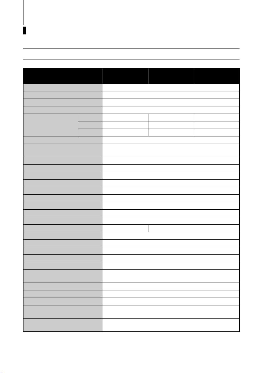
ENOM00301-0
MF, EF, EFT
Item MODEL
Overall Length mm (in) 980 (38.6)
Overall Width mm (in) 365 (14.4)
Overall Height S·L·UL mm (in) 1065 (41.9) 1215 (47.8) 1342 (52.8)
Transom Height S·L·UL mm (in) 413 (16.3) 562 (22.1) 689 (27.1)
S kg (lb) 51.5 (114) 55.0 (121) 62.0 (136)
Weight
Output kW (ps) 15C : 11.0 (15) 20C : 14.7 (20)
Max. Operating Range rpm
Idle Speed in Forward Gear rpm 900
Idle Speed in Neutral Gear rpm 950
Engine Type 4-Stroke
Number of Cylinder 2
Bore × Stroke mm (in) 61 × 60 (2.40 × 2.36)
Piston Displacement mL (Cu in) 351 (21.42)
Exhaust System Through hub exhaust
Cooling System Water cooling
Engine Lubrication Trochoid pump
Starting System Manual Electric starter motor*
Ignition System Flywheel Magneto C.D. ignition
Spark Plug NGK DCPR6E
Tri m Po si tio n 6
Engine Oil mL (fl.oz.) API SF, SG, SH, SJ, SL or SM FCW 10W-30, Approx. 1000 (33.8)
Gear Oil mL (fl.oz.) Genuine Gear Oil or API GL5, SAE #80-90, Approx. 370 (12.5)
Fuel
Fuel Tank Capacity L (US gal) 12 (3.17)
Gear Reduction Ratio 2.15 (13 : 28)
Emission Control System EM (Engine modification)
Operator Sound Pressure
(ICOMIA 39/94) dB (A)
Hand Vibration Level
(ICOMIA 38/94) m/sec2
*: with manual
Remark: Specifications subject to change without notice.
L kg (lb) 53.0 (117) 56.5 (125) 63.5 (139)
UL kg (lb) 54.5 (120) 58.0 (128) 65.0 (142)
15C MF
20C MF
Unleaded regular gasoline : Pump posted
87 Octane (research octane rating of 91)
15C EF
20C EF
15C: 5000-6000
20C: 5400-6100
83.9
2.5
15C EFT
20C EFT
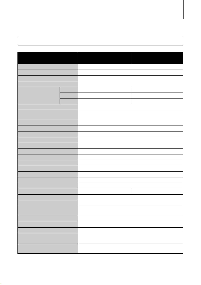
ENOM00302-0
EP, EPT
SPECIFICATIONS 11
Item MODEL
Overall Length mm (in) 640 (25.2)
Overall Width mm (in) 345 (13.6)
Overall Height S·L·UL mm (in) 1065 (41.9) 1215 (47.8) 1342 (52.8)
Transom Height S·L·UL mm (in) 413 (16.3) 562 (22.1) 689 (27.1)
S kg (lb) 54.0 (119) 61.0 (134)
Weight
Output kW (ps) 15C: 11.0 (15) 20C: 14.7 (20)
Max. Operating Range rpm
Idle Speed in Forward Gear rpm 900
Idle Speed in Neutral Gear rpm 950
Engine Type 4-Stroke
Number of Cylinder 2
Bore × Stroke mm (in) 61 × 60 (2.40 × 2.36)
Piston Displacement mL (Cu in) 351 (21.42)
Exhaust System Through hub exhaust
Cooling System Water cooling
Engine Lubrication Trochoid pump
Startring System Electric starter motor*
Ignition System Flywheel Magneto C.D. ignition
Spark Plug NGK DCPR6E
Tri m Po si tio n 6 5
Engine Oil mL (fl.oz.) API SF, SG, SH, SJ, SL or SM FCW 10W-30/40, Approx. 1000 (33.8)
Gear Oil mL (fl.oz.) Genuine Gear Oil or API GL5, SAE #80-90, Approx. 370 (12.5)
Fuel
Fuel Tank Capacity L (US gal) 12 (3.17)
Gear Reduction Ratio 2.15 (13 : 28)
Emission Control System EM (Engine modification)
Operator Sound Pressure
(ICOMIA 39/94) dB (A)
Hand Vibration Level
(ICOMIA 38/94) m/sec2
*: with manual
Remark: Specifications subject to change without notice.
L kg (lb) 55.5 (122) 62.5 (138)
UL kg (lb) 57.0 (126) —
15C EP
20C EP
15C: 5000-6000
20C: 5400-6100
Unleaded regular gasoline: Pump posted
87 Octane (research octane rating of 91)
83.9
—
15C EPT
20C EPT
12
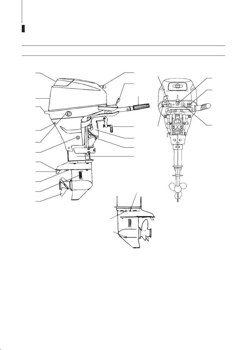
NAMES OF PARTS
ENOM00303-0
MF, EF, EP, EFT, EPT
10
11
1
18
19
20
17
16
21
2
3
4
5
6
15
14
13
12
23
22
7
8
9
24
25
26
1
Tilt Handle
2
Top Cowl
3
Bottom Cowl
4
Cooling Water Check Port
5
Power Tilt Switch
(EPT and EFT type only)
6
Oil Drain Bolt
7
Anti Ventilation Plate
8
Anode/Trim Tab
9
Sub Water Inlet
10
Water Inlet
11
Propeller
12
Drive Shaft Housing
13
Thrust Rod
14
Clamp Bracket
15
Clamp Screw
16
Throttle Grip
17
Shift Lever
18
Starter Handle
19
Stop Switch
20
Warning Lamp
21
Fuel Connector
22
Starter Switch
23
Choke Knob
ENOF00301-0
24
Water Plug
25
Oil Plug (Upper) (Level)
26
Oil Plug (Lower) (Fill)
*1
*1
*2
*1
*1: MF, EF and EFT type only.
*2: EF and EFT type only.
MF, EF, EP, EFT, EPT
NAMES OF PARTS 13
27
32
35
40
36
37
38
28
EP/EPT
31
29
39
*3
30
33
34
Power Tilt Type
35
EFT
*4
27
Primer Bulb
28
Fuel Tank Cap
29
Air Vent Screw
30
Fuel Connector
31
Fuel Pick up Elbow
32
Fuel Tank
33
Clamp Screw
(EFT type only)
34
Power Tilt
35
Power Tilt Switch
(EPT type only)
36
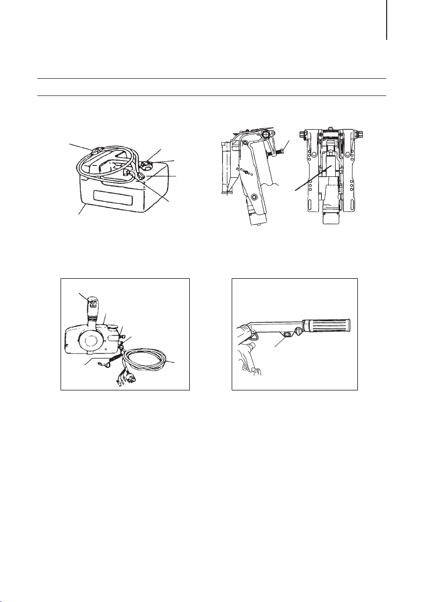
Remote Control Box
37
Main Switch
38
Stop Switch
39
Cord Assembly
40
Engine Stop Switch Cord
*3: EP and EPT type only.
*4: EFT type only.
ENOF00302-0
14
LOCATION OF WARNING LABELS
ENOM00305-0
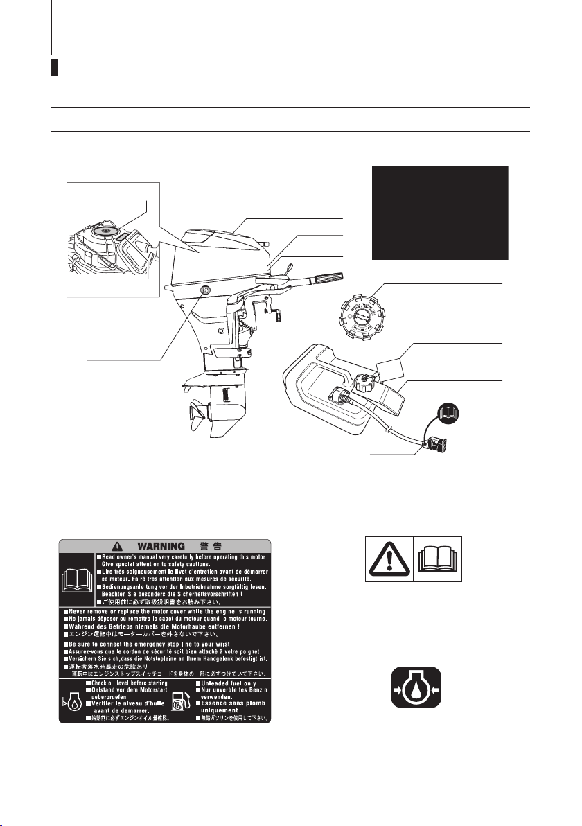
Locations of warning labels
6
5
4
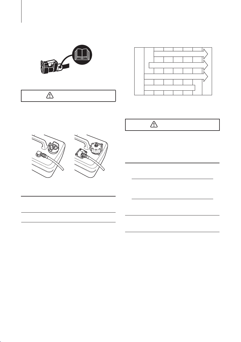
1.
Warning label regarding owner’s manual, top cowl, engine stop switch,
engine oil level and unleaded gasoline.
1
2
3
11
2.
Only for EU remote control model
ENOF00303-0
Warning label regarding installation of
remote control system (See page 20).
7
8
9
10
ENOF00005-0
ENOF00120-0
3.
Warning label regarding oil pressure
(See page 28).
ENOF00131-0
4.
Warning label on position of outboard
motor when setting down.
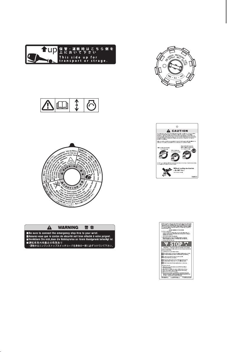
5.
ENOF00006-0
ENOF00008-0
ENOF00011-0
Only for EU model
Warning label regarding emergency
starting (See page 34).
ENOF00128-0
6.
Warning label regarding rotating parts,
electrical shock and high temperature.
1
LOCATION OF WARNING LABELS 15
ENOF00012-0
9.
Only for USA and CANADA models
Warning regarding combination of fuel
tank and primer bulb ass’y.
2
7.
Warning label on engine stop switch.
8.
Only for USA and CANADA models
Warning regarding fuel tank cap
(See pages 25, 29–32).
ENOF00129-0
ENOF00010-0
10.
Only for USA and CANADA models
When opening or closing fuel tank cap,
be sure to observe warning note on
fuelling.
11.
Only for USA and CANADA models
Warning regarding fuel connector
(See pages 25, 29–32).
LOCATION OF WARNING LABELS16
ENOF00114-0
ENOF00117-0
ENOM00023-0
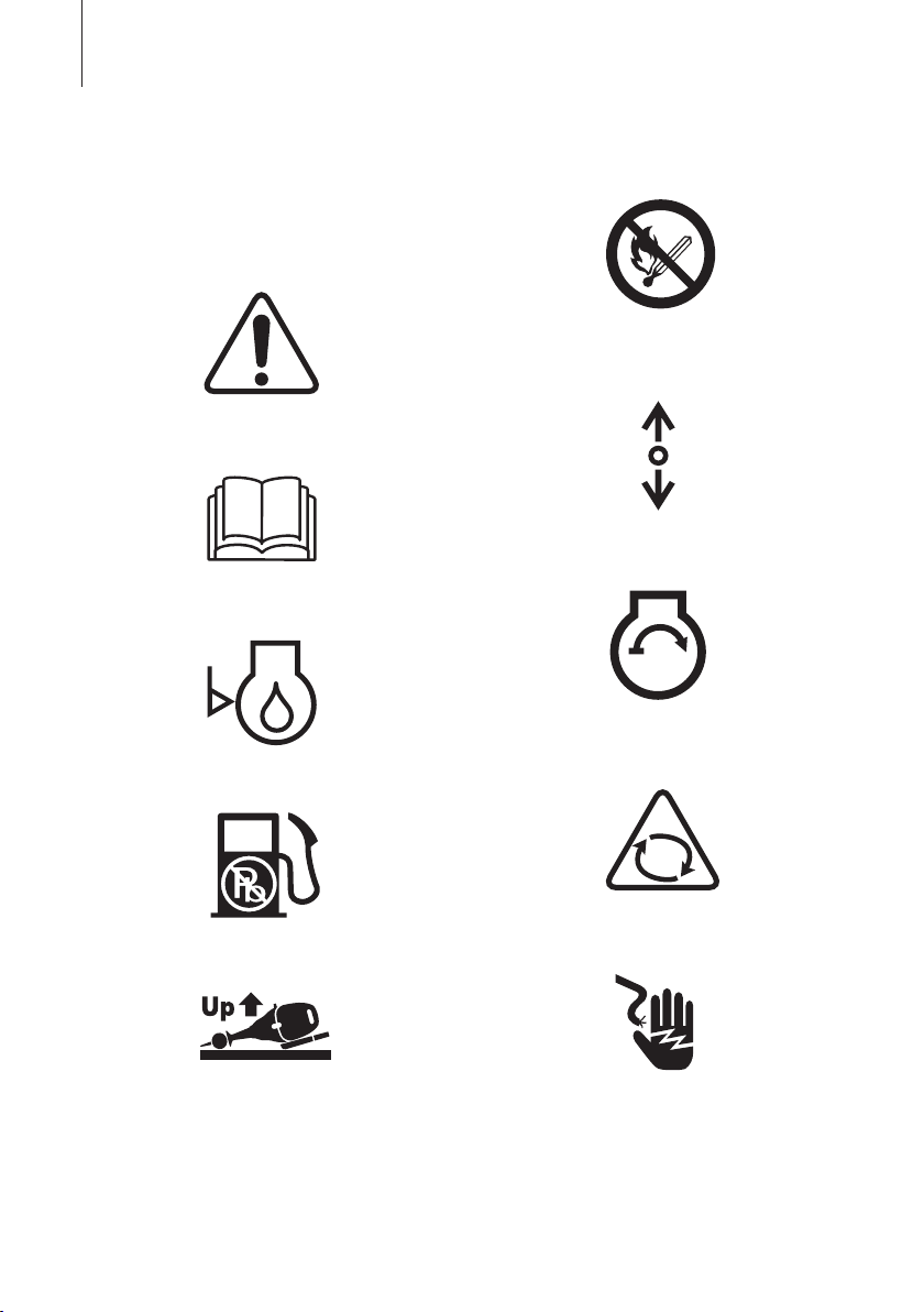
Symbols
Individual symbol marks means as
described below.
Warning/Caution
Read manual thoroughly
ENOF00115-0
Check oil level
ENOF00116-0
Use unleaded gasoline only
Flammable - Keep Fire Away
ENOF00119-0
Gear shift lever operation direction,
dual direction
ENOF00122-0
Engine start/Engine cranking
ENOF00123-0
Warning, rotating object
Lay as indicated
ENOF00118-0
ENOF00249-0
Warning, high voltage
ENOF00204-0

Warning, high temperature
LOCATION OF WARNING LABELS 17
ENOF00205-0
18
INSTALLATION
ENOM00024-0
1. Mounting the outboard motor on boat
ENOW00006-0
WARNING
Most boats are rated and certified in terms
of their maximum allowable horsepower,
as shown on the boat’s certification plate.
Do not equip your boat with an outboard
motor that exceeds this limit. If in doubt,
contact your dealer.
Do not operate the outboard motor until it
has been securely mounted on the boat in
accordance with the instructions below.
ENOM00025-0
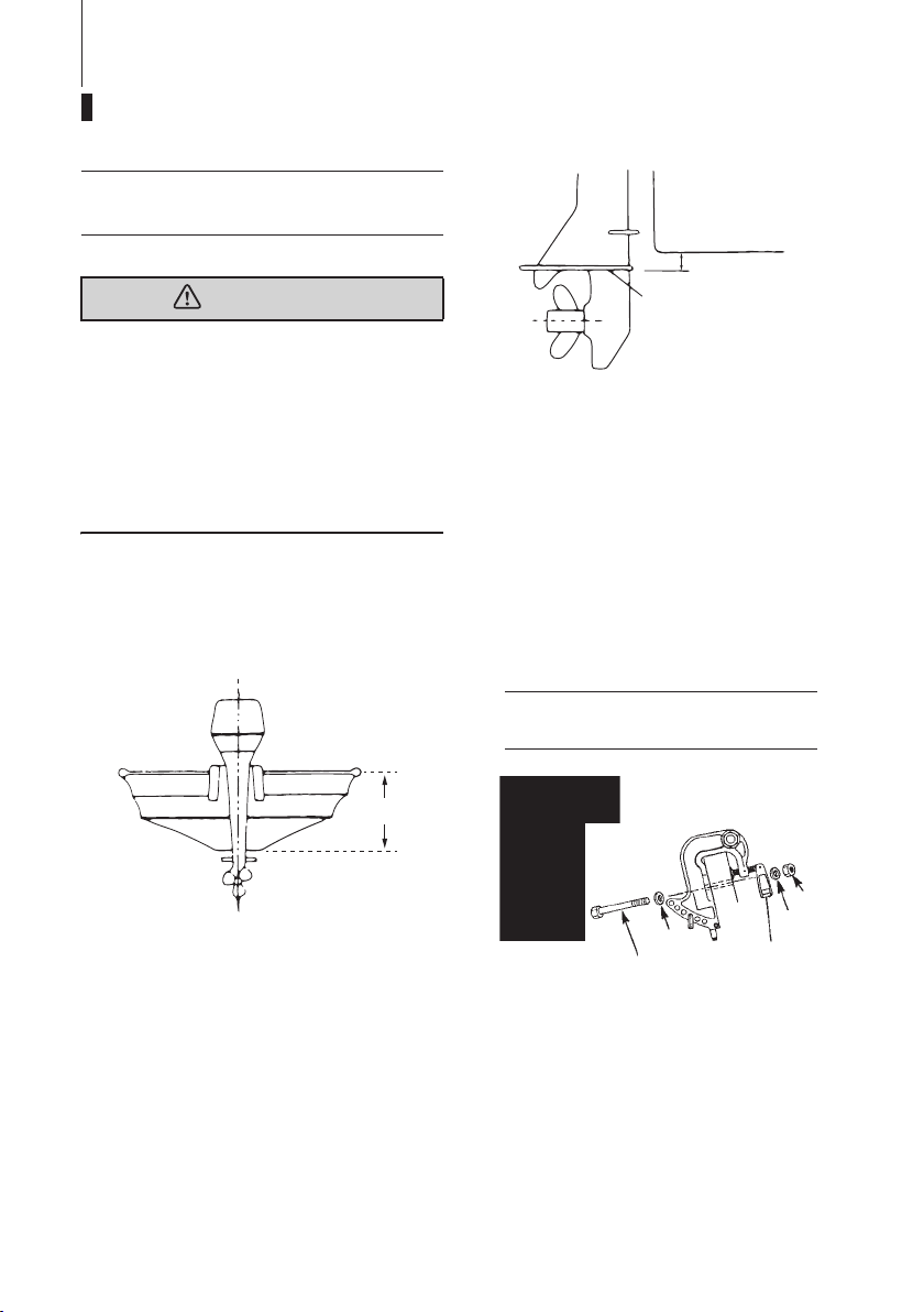
Position ... Above keel line
Set engine at center of boat.
1
1
5−25 mm
(0.2−1 in)
2
ENOF00015-0
1. Bottom of hull
2. Anti ventilation plate
ENOM00306-0
MF, EF, EP type
1. To attach the outboard motor to the
boat, tighten the clamp screws by
turning their handles.
Also, tighten the bolts. Secure the outboard motor with a rope to prevent
loss overboard.
ENON00002-0
Note
A rope is not included in the standard
accessories.
2
ENOF00014-0
1. Center of boat
2. Boat transom
ENOM00509-0
Transom matching
Be sure that the anti ventilation plate of the
outboard motor is below the water surface
when running with the throttle wide open.
If the above condition cannot be met due
to the shape of the bottom of your boat,
please consult your authorized dealer.
1. Bolt (8 × 85)*
2. Nut*
3. Washer*
4. Clamp screw
5. Washer*
*: Option
1*
5*
2*
3*
4
ENOF00304-0
ENOW00007-0
CAUTION
z Before beginning the running test, check
that the boat with maximum capacity
loading floats on the water in a proper
attitude. Check the position of water
surface on the driveshaft housing. If the
water surface is near the bottom cowling, in high waves, water may enter the
engine cylinders.
z Incorrect outboard motor mounting
height or existence of underwater
object(s), such as hull bottom design,
bottom surface conditions or underwater accessories, can cause water spray
possibly reaching the engine through an
opening of the bottom cowling during
cruising. Exposing the engine to such
conditions for extended periods can
lead to severe engine damage.
ENOM00309-0
EFT, EPT type
2. Power Tilt and Gas Assist type
1
A
4
2
3
1. Clamp screw (EFT type only)
2. Bolt (8 × 85)
3. Washer
4. Nut
5. Washer
5
ENOF00308-0
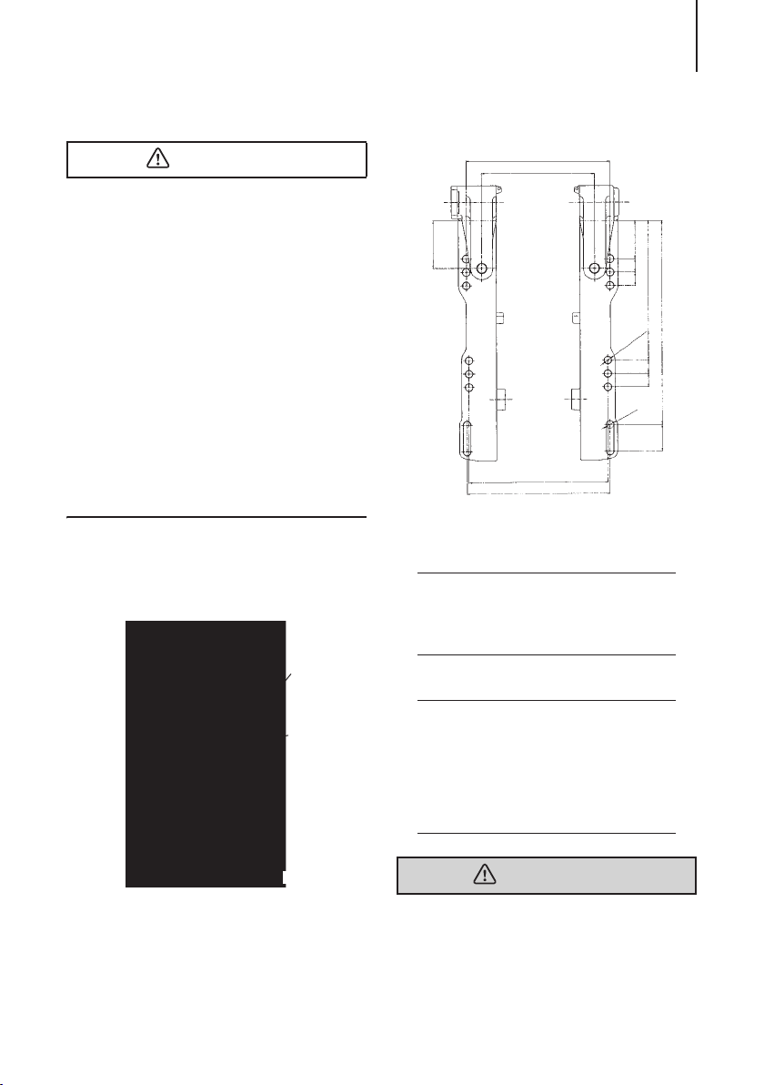
INSTALLATION 19
194
152
51
1818
188
10
∅
12-
1818
11
∅
ENOF00305-0
275
36
View A
ENON00401-0
64
187
193
Note
It is recommended to install upper mounting
bolts with bolt head at inside surface of transom. Bolts with threaded end at inside surface of transom can cause personal injury.
ENON00003-0
Notes
1. Apply sealing agent, such as silicone
sealed between the bolts and the transom board holes before tightening the
bolts.
2. Be sure to tighten the mounting bolt
nuts to the specified torque.
(30 Nm (3.0 kgf) 13 ft-lb)
ENOW00009-0
WARNING
z Mounting the outboard motor without
following this manual can lead to unsafe
conditions such as poor maneuverability, lack of control or fire.
INSTALLATION20
z Loose clamp screws and/or mounting
bolts can lead to the release or displacement of the outboard motor, possibly
resulting in lost of control and/or serious
personal injury. Be sure that fasteners
are tightened to the specified torque (30
Nm (3.0 kgf) 13 ft-lb). Check the fasteners for tightness from time to time.
z Be sure to use outboard mounting fas-
teners included in the outboard motor
package or their equivalents in terms of
size, material, quality and strength.
Tighten fasteners to the specified torque
(30 Nm (3.0 kgf) 13 ft-lb). Test cruise to
check if fasteners are tightened
securely.
z Outboard motor mounting must be per-
formed by trained service person(s)
using lift or hoist with sufficient capacity.
ENOM00028-0
2. Installing the remote control devices
ENOW00010-0
WARNING
When using other than Tohatsu’s genuine
remote control box, DO NOT select the one
without neutral safety switch that prevents
in-gear start.
Use of remote control box without neutral
safety switch can allow start of engine with
gear at other than neutral shift, potentially
leading passengers to falling or causing
passenger to be thrown overboard.
z Installation of the Remote Control on
your boat:
Follow the instruction manual provided
with the remote control.
z Installation of the Remote Control Cable
(engine side) and the Cord Assembly
(Wiring Harness):
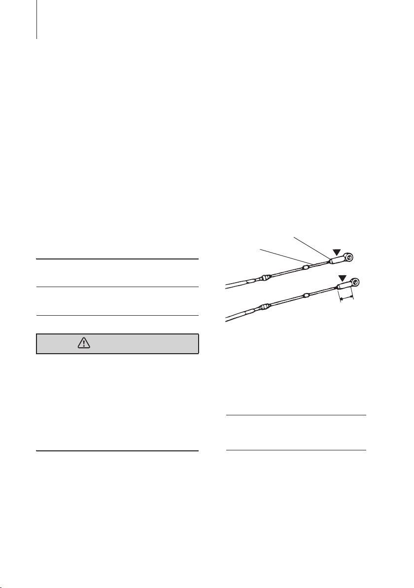
1. Fitting of connecting parts to cables
Screw the tip of the remote control
cable into the cable joint up to approx.
10 mm (0.39 inch), then lock them with
a lock nut. Apply grease to the hole of
the cable joint.
1
1. Remote control cable
2. Lock nut
3. Cable joint
2
3
10 mm
(0.39 in)
ENOF00019-0
2. Fitting of Remote Control Cable to
Engine.
ENON00004-0
Note
Put the control lever in the Neutral position
and the Free Accel lever in the fully closed
position.
It is recommended that you consult with
your authorized dealer for installation and
adjustment of the remote control device.
z Installation of the Remote Control
Cables (Box side):
Follow the instruction manual provided
with the remote control.
INSTALLATION 21
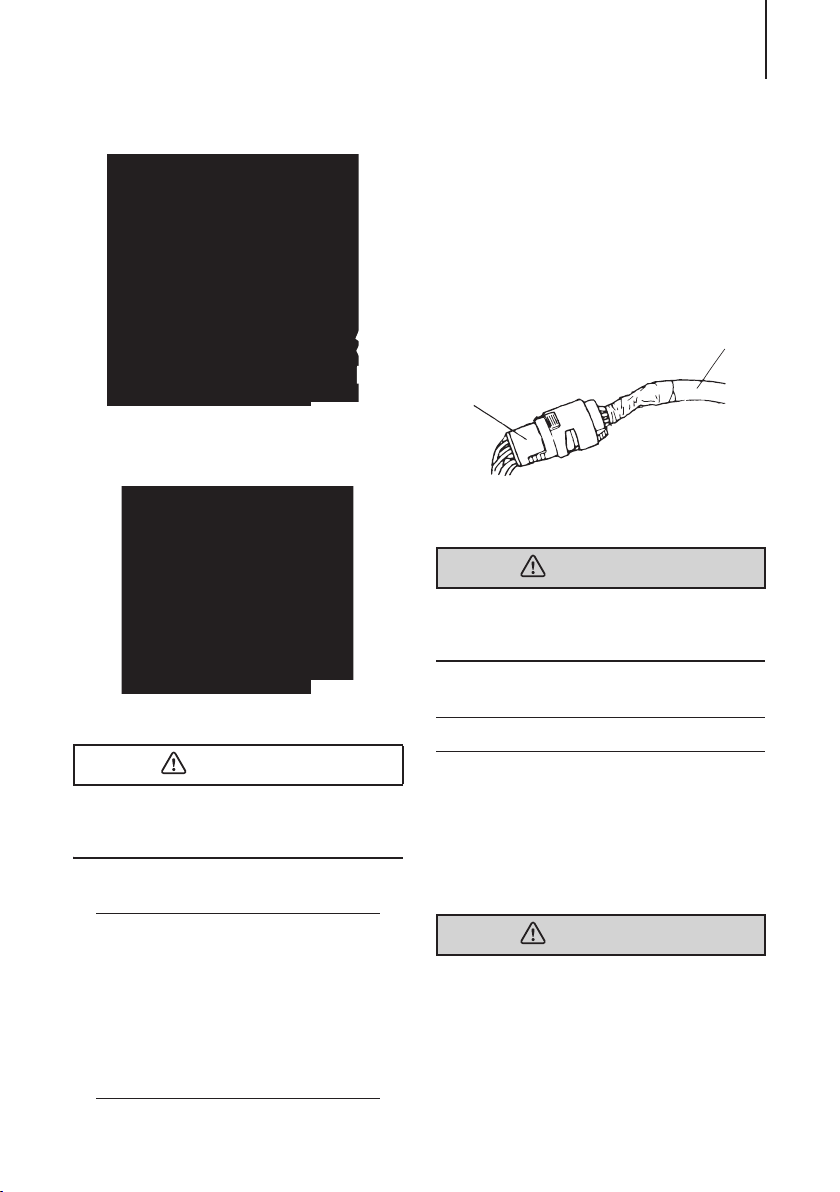
3. Connecting the Cord assembly (Wiring
Harness).
Connect cable harness B to cable harness A.
Location of the connectors is near the
recoil starter of starboard side in the
cowl.
1
2
3
ENOF00306-0
1. Cable harness B
2. Shift cable
3. Throttle cable
1
ENOF00307-0
1. Drag link
ENOW00100-0
CAUTION
Be careful not to loop the remote control
cables to a diameter of 406 mm (16 inches)
or less.
ENON00301-0
Note
Confirm whether the shift of engine is in
gear when shifting the control lever of the
Remote Control to its first position in Forward or Reverse (about 32°) and whether
the throttle valve is fully open when shifting
the lever further.
Confirm whether the throttle valve is fully
closed when the control lever is shifted to
the Neutral position.
2
1
ENOF00021-0
1. Cable Harness A (Outboard motor side)
2. Cable Harness B (From remote control)
ENOW00011-0
WARNING
Do not disconnect the cord assembly when
the outboard motor is in operation or you
will lose control of the outboard motor.
ENOM00029-0
3. Installing the battery
1. Place the battery box in a convenient
position away from possible water
spray. Securely fasten both the box
and the battery so they do not shake
loose.
ENOW00012-0
WARNING
Battery electrolyte contains sulfuric acid
and thus is hazardous, causing a burn if it
comes in contact with your skin, or poisonous if swallowed.
Keep battery and electrolyte away from
reach of children.
INSTALLATION22
2
1
ENOF00022-0
When handling the battery, be sure to:
z Read all warnings shown on the battery
case
z Prevent electrolyte from coming in con-
tact with any part of your body. Contact
can cause serious burn or, if it comes in
contact with your eye, loss of sight. Use
safety glasses and rubber gloves.
In case battery electrolyte comes in contact with:
z Skin, flush thoroughly with water.
z Eye, flush thoroughly with water, and
then seek immediate medical treatment.
In case battery electrolyte is swallowed:
z Seek immediate medical treatment.
ENON00302-0
Note
Minimum recommended battery: 12V, 70AH
(800 Marine Cranking Amps (MCA) or 650
Cold Cranking Amps (CCA))
Specifications and features of batteries vary
among the manufacturers. Consult the
manufacturer for details.
ENOW00013-0
WARNING
Battery generates explosive hydrogen gas.
Be sure to:
z Charge the battery in a well-ventilated
place.
z Place the battery away from any source
of fire, sparks and open flames such as
burners or welding equipment.
z Do not smoke when handling the bat-
tery.
z Do not smoke near the battery when the
battery is charging.
ENOW00014-0
z The starter motor may fail to operate if
the leads are incorrectly connected.
z Be sure to correctly connect the (+) and
(—) leads. If not, the charging system
will be damaged.
z Do not disconnect the battery leads
from battery while the engine is operating, the electrical parts could be damaged.
z Always use a fully charged battery.
ENOW00015-0
CAUTION
Do not use a battery that is not recommended. Use of a battery not recommended can lead to poor performance of,
and/or damage to, the electrical system.
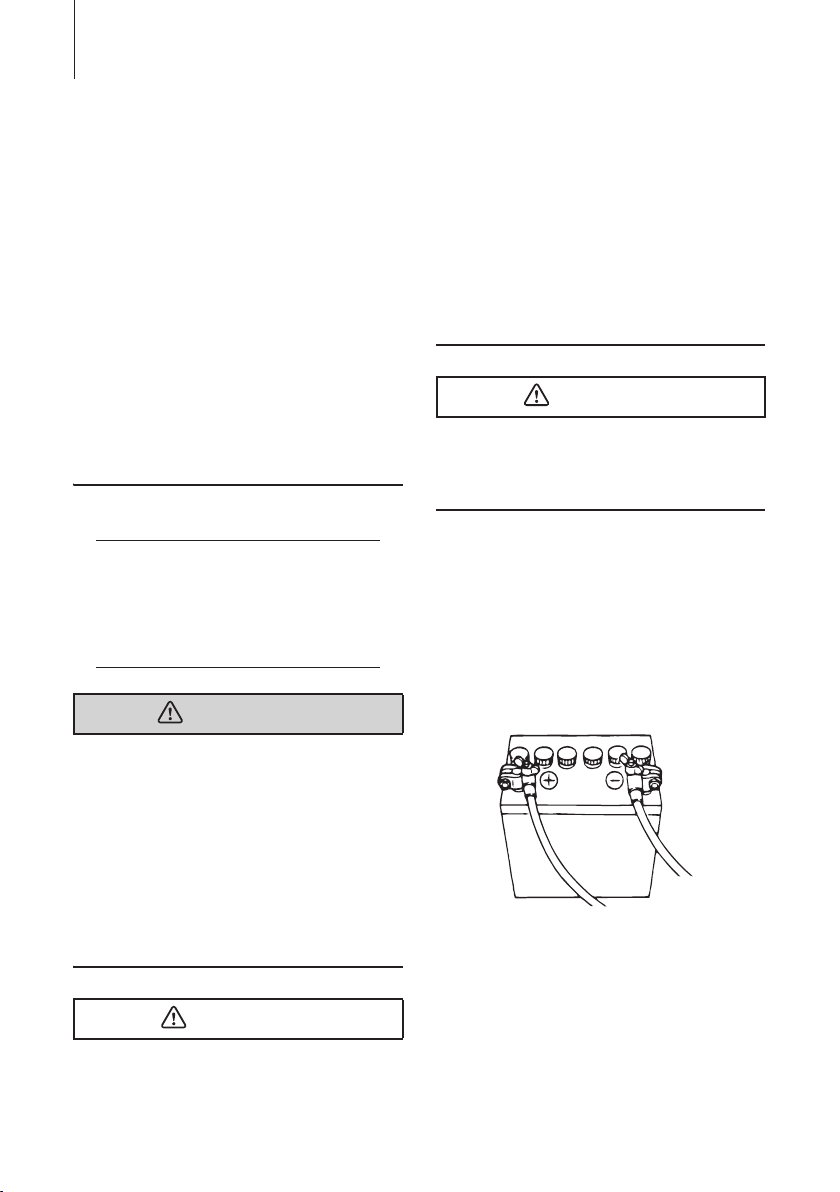
2. Connect the positive lead (+) to the
positive terminal (+) of the battery, and
then connect the negative lead (—).
When disconnecting the battery
always remove the negative lead (—)
first. After connecting the positive terminal (+), securely place a cap on it to
prevent short circuits.
1. Battery cord (red)
2. Battery cord (black)
CAUTION
z Make sure that the battery leads do not
get stuck between the outboard motor
and boat when turning, etc.
PRE-OPERATING PREPARATIONS
23
ENOW00016-0
DANGER
Consult an authorized dealer for details on
handling gasoline, if necessary.
Gasoline and its vapors are very flammable
and can be explosive.
When carrying a fuel tank containing gasoline:
z Close the air vent screw of fuel tank cap,
or gasoline vapor will be emitted
through the air vent screw, creating a
fire hazard.
z Do not smoke.
When or before refueling:
z Stop the engine, and do not start the
engine during refueling.
z Do not smoke.
z Be careful not to overfill fuel tank. Wipe
up any spilled gasoline immediately.
When or before cleaning the gasoline tank:
z Dismount fuel tank from the boat.
z Place the fuel tank away from every
source of ignition, such as sparks or
open flames.
z Do the work outdoors or in a well venti-
lated area.
z Wipe off gasoline well immediately if
spilt.
After cleaning gasoline tank:
z Wipe off gasoline well immediately if
spilt.
z If the fuel tank is disassembled for
cleaning, reassemble carefully. Imperfect assembly may cause a fuel leak,
possibly leading to fire or explosion.
z Dispose aged or contaminated gasoline
in accordance with local regulations.
ENOM00030-0
1. Recommended gasoline types
ENOW000017-0
CAUTION
Use of improper gasoline can damage your
engine. Engine damage resulting from the
use of improper gasoline is considered
misuse of the engine, and damage caused
thereby will not be covered under the limited warranty.
ENOM00031-0
FUEL RATING
TOHATSU engines will operate satisfactorily when using a major brand of unleaded
gasoline meeting the following specifications:
USA and Canada — having a posted
pump Octane Rating of 87 (R+M)/2 minimum. Premium gasoline (92 [R+M]/2
Octane) is also acceptable. Do not use
leaded gasoline.
Outside USA and Canada — Use
unleaded gasoline with declared octane
rating of 90 RON or over. Use of premium
gasoline of 98 RON is also allowed. Use of
name-brand leaded gasoline may be
allowed only if unleaded gasoline is not
available.
ENOM00514-0
GASOLINES CONTAINING
ALCOHOL
The fuel system components on your
TOHATSU engine will withstand up to 10%
alcohol content in the gasoline. But if the
gasoline in your area contains either methanol (methyl alcohol) or ethanol (ethyl alcohol), you should be aware of certain
PRE-OPERATING PREPARATIONS24
adverse effects that can occur. These
adverse effects are more severe with
methanol. Increasing the percentage of
alcohol in the fuel can also worsen these
adverse effects. Some of these adverse
effects are caused because the alcohol in
the gasoline can absorb moisture from the
air, resulting in a separation of the water/
alcohol from the gasoline in the fuel tank.
These may cause increased:
z Corrosion of metal parts
z Deterioration of rubber or plastic parts
z Fuel permeation through rubber fuel
lines
z Starting and operating difficulties
ENOW00018-0
WARNING
Fuel leakage can cause fire or explosion,
potentially leading to severe injury or loss
of life. Every fuel system part should be
checked periodically, and especially after
long term storage, for fuel leak, change of
hardness of rubber, expansion and/or corrosion of metals. In case any indication of
fuel leakage or degradation of fuel part is
found, replace relevant part immediately
before continuing operation.
If the use of gasoline containing alcohol is
inevitable, or presence of alcohol is suspected in the gasoline, it is recommended
to add a filter that has water separating
capability, and check the fuel system for
leaks and mechanical parts for corrosion
and abnormal wear more frequently.
And, in case any of such abnormality is
found, discontinue the use of such gasoline and contact our dealer immediately.
Damages resulting from the use of gasolines that contain alcohol are not covered
under the limited warranty.
Fuel tank capacity:
12 liters (3.17 U.S. gal)
Fuel Tank: When using a fixed fuel tank in
place of genuine fuel tank, it is recommended to select a one with a structure
facilitating interior cleaning.
ENOW00019-0
WARNING
Do not fill the fuel tank over capacity. The
rise of gasoline temperature may cause
gasoline to expand which, if overfilled, may
leak through air vent screw when it is open.
Leaking gasoline is a dangerous fire hazard.
ENOW00020-0
CAUTION
When operating a TOHATSU engine on
gasoline containing alcohol, storage of
gasoline in the fuel tank for long periods
should be avoided. Long periods of storage, common to boats, create unique problems. In cars, alcohol blend fuels normally
are consumed before they can absorb
enough moisture to cause trouble, but
boats often sit idle long enough for phase
separation to take place. In addition, internal corrosion may take place during storage if alcohol has washed protective oil
films from internal components.
ENOM00033-0
2. Low permeation fuel hose requirement
EQUIPPED FOR UNITED STATES AND
CANADA MODEL
Required for outboards manufactured for
sale, sold, or offered for sale in the United
States
PRE-OPERATING PREPARATIONS 25
1
2
3
ENOF00023-0
z TOHATSU engine has used fuel hoses
for The Environmental Protection
Agency (EPA) requires from January 1,
2011.
ENOM00034-0
3. EPA pressurized portable fuel tank requirements
EQUIPPED FOR UNITED STATES AND
CANADA MODEL
The Environmental Protection Agency
(EPA) required portable fuel systems that
are produced after January 1, 2011 for use
with outboard engines to remain fully
sealed (pressurized) up to 34.4 kPa (5.0
psi). These tanks may contain the following:
z An air inlet that opens to allow air to
enter as the fuel is drawn out of the
tank.
z An air outlet that opens (vents) to the
atmosphere if pressure exceeds 34.4
kPa (5.0 psi). A hissing noise may be
heard as the tank vents to the atmosphere. This is normal.
z When installing the fuel tank cap, turn
the cap to the right until you hear two
clicks. This signals that the fuel cap is
fully seated. A built-in device prevents
overtightening.
z The fuel tank has a manual vent screw
which should be closed for transportation and full open for operation and cap
removal.
Since sealed fuel tanks are not openly
vented, they will expand and contract as
the fuel expands and contracts during
heating and cooling cycles of the outside
air. This is normal.
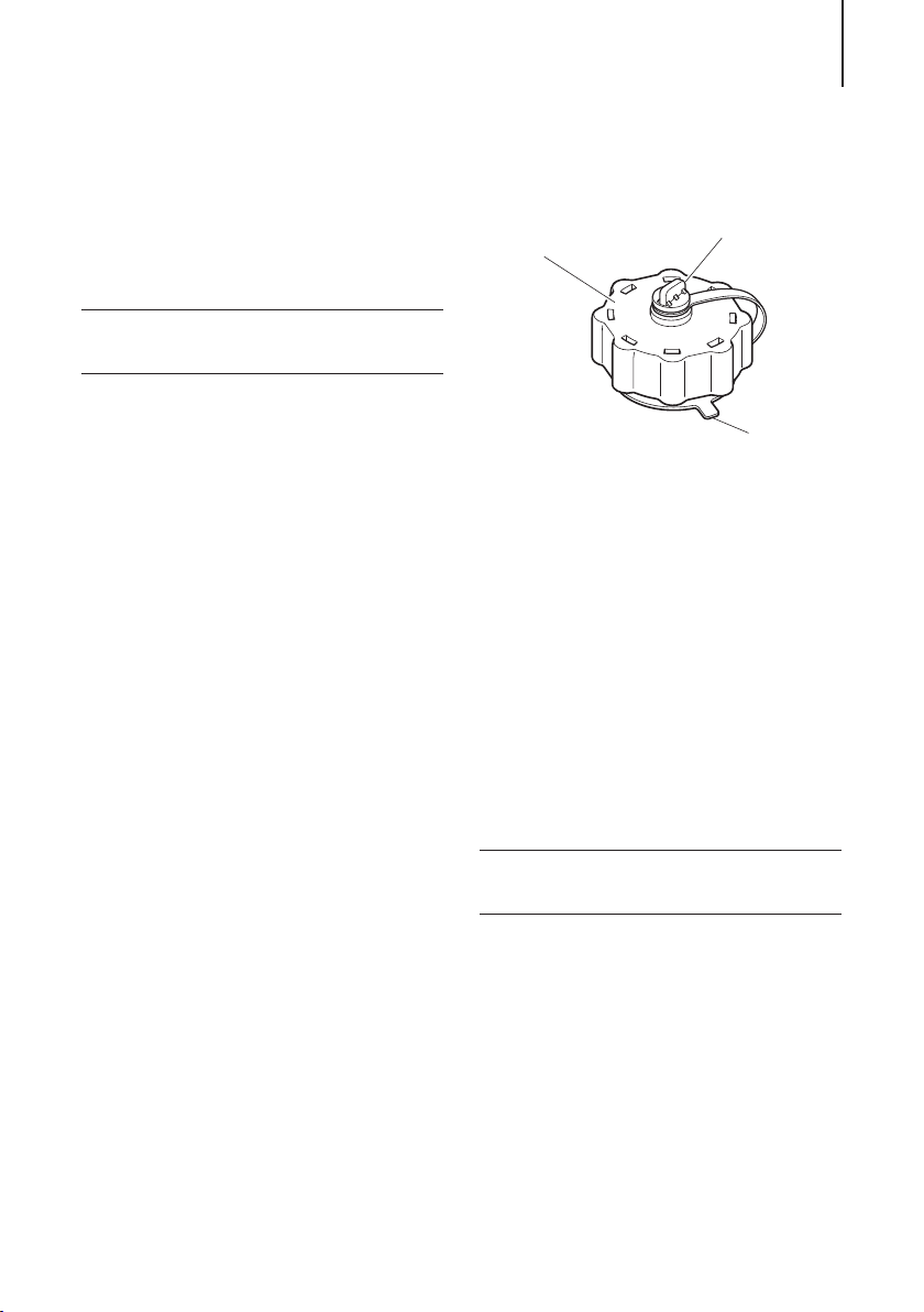
ENOM00035-0
REMOVING THE FUEL CAP
1. Fuel cap
2. Manual vent screw
3. Tab l oc k
IMPORTANT: Contents may be under
pressure. Rotate the fuel cap 1/4 turn to
relieve pressure before opening.
1. Open the manual vent screw on top of
the fuel cap completely.
2. Turn the fuel cap until it contacts the
tab lock.
3. Press the tab lock and turn to remove
cap.
ENOM00036-0
4. EPA approval Primer valve/hose assembly
EQUIPPED FOR UNITED STATES AND
CANADA MODEL
TOHATSU adopts Primer bulb/hose
assembly approved by the Environment
Protection Agency (EPA).
Please use the EPA approved primer bulb/
hose assembly with the identification mark
on the fuel connector.
PRE-OPERATING PREPARATIONS26
20W−40, 20W−50
15W−40, 15W−50
10W−40, 10W−50
10W−30
˚C
˚F
40
96
30
86
20
68
10
50
0
32
-10
14
-20
-4
-30
-22
ENOF00025-0
ENOF00111-0
ENOW00021-0
CAUTION
Be sure to use EPA approved tank and EPA
approved primer bulb/hose assembly as a
set. Confirm shapes of EPA approved tank
and regular tank.
12
1. Except for U.S. model (regular tank)
2. For U.S. and Canada model (EPA approved tank)
ENOF00414-0
ENOW00022-0
CAUTION
The engine oil is drained for shipping from
the factory. Be sure to fill the engine to the
proper level before starting engine. (To
properly fill the engine with oil follow the
instructions in section 10 of this manual)
ENON00007-0
Note
Use of engine oils that do not meet these
requirements will result in reduced engine
life, and other engine problems.
ENOM00037-0
5. Recommended engine oil
Use only high quality 4-stroke engine oil to
insure performance and prolonged engine
life.
Use NMMA FC-W certified 4-stroke engine
oil below.
10W-30: is recommended for use in all
temperature.
25W-40: may be used at temperatures
above 4°C (40°F).
You can also use oils that carry the API rating of SF, SG, SH, SJ, SL, or SM. Select
the appropriate viscosity, based on atmospheric temperature, from the chart below.
ENOM00331-0
6. Altitude adjustment kit requirement
For U.S.A. market only
High altitude:
When engine operates at high altitude
engine may need to have a high altitude kit
installed. Otherwise, operating the engine
at high altitude may increase its emissions
and decrease fuel efficiency and performance. Please see “LIMITED WARRANTY
INFORMATION” for more detail.
ENOM00038-0
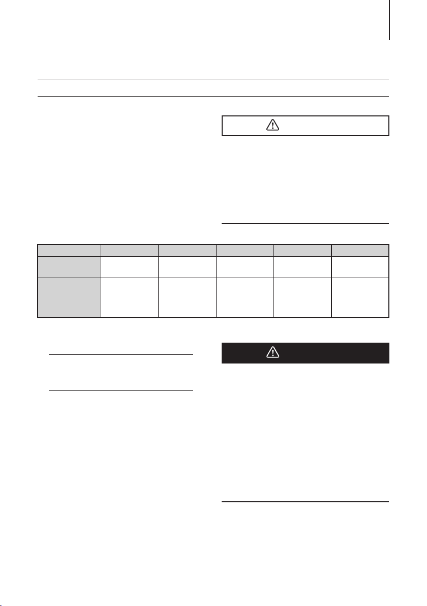
7. Break-In
PRE-OPERATING PREPARATIONS 27
Your new outboard motor and lower unit
require break-in for the moving components according to the conditions
described in the following time table.
1–10 min 10 min – 2 hrs 2–3 hrs 3–10 hrs After 10 hrs
Throttle Position Idle
Speed
ENON00008-0
Less than 1/2
throttle
Approx. 3000
rpm max
Note
Proper break-in allows outboard motor to
deliver it full performance for longer service
life.
ENOW00023-0
CAUTION
Operating the outboard motor without
break-in can shorten service life of the
product.
If any abnormality is experienced during
the break-in:
z Discontinue the operation immediately.
z Have the dealer check the product and
take proper action(s) if necessary.
Less than 3/4
throttle
Full throttle run
allowed for 1
min every 10 min
ENOW00024-0
3/4 throttle
Approx. 4000
rpm. Full throttle
run allowed for 2
min every 10 min
Full throttle avail-
able
DANGER
Do not operate the outboard motor in
closed area or area with no forced ventilation.
Exhaust gas emitted by this outboard
motor contains carbon monoxide that will
cause death if inhaled continuously. Inhaling the gas initially causes symptoms such
as feeling of sickness, drowsiness and
headache.
During operation of the outboard motor:
z Keep peripheral area well ventilated.
z Always attempt to stay on the windward
side of emission.
PRE-OPERATING PREPARATIONS28
ENOM00315-0
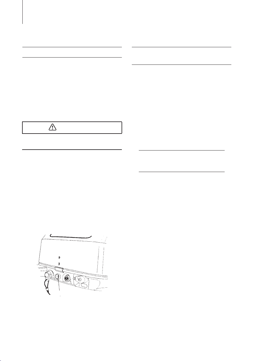
8. Engine oil warning lamp
Oil pressure is required to lubricate internal
engine parts.
When the warning lamp (Red) is off, indicates that oil pressure is present.
Remark: When engine is first started, the
red light will turn on for several seconds to
confirm that it is working and then turn off.
ENOW00402-0
CAUTION
Never run the engine if the warning lamp is
on or blinking on and off.
When the warning lamp is on or blinking
on and off, as an additional alert of the low
oil pressure condition, the engine will run
rough and not exceed 2000 rpm;
* Stop the engine immediately and check
the engine oil level.
If the oil level is lower than the appropriate level: Replenish engine oil.
If the oil level is within the appropriate
level: Consult with your dealer.
ENOM00330-0
9. ESG (A device preventing over revolution)
ESG is a device to prevent over revolution
of the engine (more than approximately
6400 rpm).
If you sense that the ESG is activated
return to shore at a reduced speed (rpm).
Possible causes of ESG activation are:
Worn, broken, bent propeller. Slipping propeller rubber, Making sharp turns at high
speeds.
ENON00202-0
Note
If the engine speed drops frequently after
restarting the engine, please contact your
dealer.
1. Warning lamp
1
ENOF00309-0

ENGINE OPERATION
29
ENOM00042-0
Before starting
ENOW00026-0
CAUTION
The engine oil is drained for shipping from
the factory. Be sure to fill the engine to the
proper level before starting engine. (To
properly fill the engine with oil follow the
instructions in section 10 of this manual)
ENOW00027-0
CAUTION
Before starting engine for the first time
after reassembling engine or off-season
storage, disconnect stop switch lock and
pull the starter handle completely out
approximately 10 times in order to prime
the oil pump.
ENOM00043-0
1. Filling the fuel
ENOW00028-0
DANGER
Consult an authorized dealer for details on
handling gasoline, if necessary.
Gasoline and its vapors are very flammable
and can be explosive.
When carrying a fuel tank containing gasoline:
z Close the fuel tank cap and air vent
screw of fuel tank cap, or gasoline vapor
will be emitted through the air vent
screw, creating a fire hazard.
z Do not smoke.
z Do not smoke.
z Be careful not to overfill fuel tank. Wipe
up any spilled gasoline immediately.
When or before cleaning the gasoline tank:
z Dismount fuel tank from the boat.
z Place the fuel tank away from every
source of ignition, such as sparks or
open flames.
z Do the work outdoors or in a well venti-
lated area.
z Wipe off gasoline well immediately if
spilt.
After cleaning gasoline tank:
z Wipe off gasoline well immediately if
spilt.
z If the fuel tank is disassembled for
cleaning, reassemble carefully. Imperfect assembly may cause a fuel leak,
possibly leading to fire or explosion.
z Dispose aged or contaminated gasoline
in accordance with local regulations.
ENOW00029-0
WARNING
When opening fuel tank cap, be sure to follow the procedure described below. Fuel
could blast out through the fuel tank cap in
case the cap is loosened by using another
procedure when internal pressure of fuel
tank is raised by heat from sources such as
engine or sun light.
Except for USA and Canada
model
1. Full open the air vent screw on the tank
cap and release internal pressure.
When or before refueling:
z Stop the engine, and do not start the
engine during refueling.
 Loading...