

TOHATSU MD 50B2, MD 40B2, MD 115B2, MD 75C2, MD90C2 Owner's Manual
...
MANUAL
30B2
40B2
50B2
115A2
MD
OWNER’S
OB No.003-11075-9

Copyright © 2009 Tohatsu Corporation. All rights reserved. No part of this manual may
be reproduced or transmitted in any from or by any means without the express written
permission of Tohatsu Corporation.
READ THIS MANUAL BEFORE USING THE OUTBOARD MOTOR. FAILURE TO FOLLOW THE
INSTRUCTIONS AND SAFETY PRECAUTIONS IN THIS MANUAL CAN RESULT IN SERIOUS
INJURY OR DEATH. KEEP THIS MANUAL IN A SAFE LOCATION FOR FUTURE REFERENCE.
!

YOUR TOHATSU OUTBOARD MOTOR
OWNER REGISTRATION AND IDENTIFICATION
Upon purchasing this product, be sure that the WARRANTY CARD is correctly and
completely filled out and mailed to the addressee noted there on. This WARRANTY
CARD identifies you as the legal owner of the product and serves as your warranty
registration.
IF THIS PROCEDURE IS NOT FOLLOWED, YOUR OUTBOARD MOTOR WILL
NOT BE COVERED BY THE APPLICABLE LIMITED WARRANTY.
PRE-DELIVERY CHECK
Be sure that the product has been checked by an authorized TOHATSU dealer
before you take delivery.
Limited Warranty
Please refer to the TOHATSU outboard motor Limited warranty provided to you with
this product, the terms and conditions of which, as amended from time to time, are
incorporated by reference into the manual.

Serial Number
In the space below, please record the outboard motor's serial number (indicated
both on the lower motor cover and on the cylinder block). The serial number will be
needed in the event of theft or to quickly identifying the outboard motor type.
Serial Number :
To You, Our Customer
Thank you for selecting a TOHATSU outboard motor. You are now the proud owner
of an excellent outboard motor that will service you for many years to come.
This manual should be read in its entirety and the inspection and maintenance
procedures described later in this manual should be followed carefully. Should
a problem arise with the outboard motor, please follow the troubleshooting
procedures listed at the end of this manual. If the problem persists, contact an
authorized TOHATSU service shop or dealer.
We hope you will enjoy your outboard motor and wish you good luck in your
boating adventures.
TOHATSU CORPORATION

・・・・・・・・・・・・・・・・・・・・・・・・・・・・・・・・・・・・・・・・・・
・・・・・・・・・・・・・・・・・・・・・・・・・・・・・・・・・・・・・・・・・・・・・・・・・・・・・・・・・・・・・・
・・・・・・・・・・・・・・・・・・・・・・・・・・・・・・・・・・・・・・・・・・・・・・・・・・・・・・・・・・・・・
・・・・・・・・・・・・・・・・・・・・・・・・・・・・・・・・・・・・・・・・・・・・・・・・・・・・・・・・・・・・・・・・・・
・・・・・・・・・・・・・・・・・・・・・・・・・・・・・・・・・・・・・・
・・・・・・・・・・・・・・・・・・・・・・・・・・・・・・・・・・・・・・・・・・・・・・・・・・・・・・・・・・・
・・・・・・・・・・・・・・・・・・・・・・・・・・・・・・・・・・・・・・・
・・・・・・・・・・・・・・・・・・・・・・・・・・・・・・・・・・・・・・・・・・・・・・・・・・・・・・・・
・・・・・・・・・・・・・・・・・・・・・・・・・・・・・・・・・・・・・・・・・・・・
・・・・・・・・・・・・・・・・・・・・・・・・・・・・・・・・・・・・・・・・・・・・・・・・・・・・・・・・
・・・・・・・・・・・・・・・・・・・・・・・・・・・・・・・・・・・・・・・・・・・
・・・・・・・・・・・・・・・・・・・・・・・・・・・・・・・・・・・・・・・・・・・・・・・・・・・・・
・・・・・・・・・・・・・・・・・・・・・・・・・・・・・・・・・・・・・・・・・・・・・・・・・・・・・・・・・・・・・・・・・・・・・・
・・・・・・・・・・・・・・・・・・・・・・・・・・・・・・・・・・・・・・・・・・・・・・・・・・・・・・・・・・・・・・
・・・・・・・・・・・・・・・・・・・・・・・・・・・・・・・・・・・・・・・・・・・・・・・・・・・・・・・・・・・
・・・・・・・・・・・・・・・・・・・・・・・・・・・・・・・・・・・・・・・・・・・・・・・・・・・・・・・・・・・・・・・・・・・・・・・
・・・・・・・・・・・・・・・・・・・・・・・・・・・・・・・・・・・・・・・・・・・・・・・・・・・・・
・・・・・・・・・・・・・・・・・・・・・・・・・・・・・・・・・・・・・・・・・・・・・・・・・・・・・・・・
・・・・・・・・・・・・・・・・・・・・・・・・・・・・・・・・・・・・・・・・・・・・・・・・・・・・・・・
・・・・・・・・・・・・・・・・・・・・・・・・・・・・・・・・・・・・・・・・・・・・・・・・・・・・・・・・・
・・・・・・・・・・・・・・・・・・・・・・・・・・・・・・・・・・・・・・・・・・・・・・・・・・・・・・・・・・・・・・・・・・・・
・・・・・・・・・・・・・・・・・・・・・・・・・・・・・・・・・・・・・・・・・・・
・・・・・・・・・・・・・・・・・・・
・・・・・・・・・・・・・・・・・・・・・・・・・・・・・・・・・・・・・・・・・・・・・・・
・・・・・・・・・・・・・・・・・・・・・・・・・・・・・・・・・・・・・・・・・・・・・・・・・
・・・・・・・・・・・・・・・・・・・・・・・・・・・・・・・・・・・・・・・・・・・・・・・・・・
・・・・・・・・・・・・・・・・・・・・・・・・・・・・・・・・・・・・・・・・・・・・・・・・・・・・・・・・・・・・・・・・・・・
・・・・・・・・・・・・・・・・・・・・・・・・・・・・・・・・・・・・・・・・・・・・・・・・・・・・・・・・・・・・・・・・・・
・・・・・・・・・・・・・・・・・・・・・・・・・・・・・・・・・・・・・・・・・・・・・・・・・・・
・・・・・・・・・・・・・・・・・・・・・・・・・・・・・・・・・・・・・・・・・・・・・・・・・・・・・・・・・・
・・・・・・・・・・・・・・・・・・・・・・・・・・・・・・・・・・・・・・・・・・・・・・・・・・・
・・・・・・・・・・・・・・・・・・・・・・・・・・・・・・・・・・・・・・・
・・・・・・・・・・・・・・・・・・・・・・・・・・・・・・・・・・・・・・・・・・
・・・・・・・・・・・・・・・・・・・・・・・・・・・・・・・・・・・・・・・・・・・・・・・・・・・・・・・・・・・・・・
・・・・・・・・・・・・・・・・・・・・・・・・・・・・・・・・・・・・・・・・・・・・・・・・・・・・・・・・・・
・・・・・・・・・・・・・・・・・・・・・・・・・・・・・・・・・・・・・・・・・・・・・・・・・・・・・・・・・・
・・・・・・・・・・・・・・・・・・・・・・・・・・・・・・・・・・・・・・・・・・・・・・・・・・・・・・・・・・・
・・・・・・・・・・・・・・・・・・・・・・・・・・・・・・・・・・
・・・・・・・・・・・・・・・・・・・・・・・・・・・・・・・・・
・・・・・・・・・・・・・・・・・・・・・・・・・・・・・・・・・・・・・・・・・・・・・・・・・
・・・・・・・・・・・・・・・・・・・・・・・・・・・・・・・・・・・・・・・・・・・・・・・・・・・・・・・・・・
・・・・・・・・・・・・・・・・・・・・・・・・・・・・・・・・・・・・・・・・・・・・・・・・
・・・・・・・・・・・・・・・・・・・・・・・・・・・・・・・・・・・・・・・・・・・・・・・・・・・・
・・・・・・・・・・・・・・・・・・・・・・・・・・・・・・・・・・・・・・・・・・・・・・・・・・・・・・・・・・・・
■
■
■
■
■
■
■
■
■
■
■
■
■
■
1
2
3
4
5
6
7
8
9
10
11
12
13
GENERAL SAFETY INFORMATION
SPECIFICATIONS
NAMES OF PARTS
INSTALLATION
1. Mounting the outboard motor on boat
2. Propeller Selection
3. Installing the remote control devices
4. Installing the meters
5. Installing the drag link assembly
6. Installing the battery
PRE-OPERATING PREPARATIONS
1.Gasoline and engine oil
2.Break-in
3.Warning system
ENGINE OPERATION
1.Starting
2.Warming up the engine
3.Forward and reverse
4.Shallow water running
5.Stopping the engine
6.Trim angle
7.Mooring with the engine tilted up
REMOVING AND CARRYING THE OUTBOARD MOTOR
1.Removing the outboard motor
2.Carrying the outboard motor
3.Storing the outboard motor
TRAILERING
ADJUSTMENT
1.Remoto control lever load
2.Trim tab adjustment
3.Steering load adjustment
4.Throttle grip turning load adjustment
INSPECTION AND MAINTENANCE
1.Daily inspection
2.Periodic inspection
3.Off-season storage
4.Pre-season check
5.Checking after striking underwater object
6.If the engine becomes submerged in water
7.Precautions in cold weather
TROUBLESHOOTING
TOOL KIT AND SPARE PARTS
OPTIONAL ACCESSORIES
PROPELLER TABLE
8
10
14
18
18
21
22
27
29
30
32
32
35
36
39
39
45
46
48
50
52
55
58
58
58
59
60
61
61
61
62
62
63
64
68
74
76
77
77
77
78
80
82
84
CONTENTS


7
1. SPECIFICATIONS
2. NAMES OF PARTS
3. INSTALLATION
4.PRE-OPERATING PREPARATIONS
5.ENGINE OPERATION
6.REMOVING AND CARRYING THE MOTOR
7.TRAILERING
8.ADJUSTMENT
9.INSPECTION AND MAINTENANCE
10.TROUBLESHOOTING
11.TOOL KIT AND SPARE PARTS
12.OPTIONAL ACCESSORIES
13.PROPELLER TABLE
1
2
3
4
5
6
7
8
9
10
11
12
13
GENERAL SAFETY INFORMATION
INDEX

NOTICE : DANGER/WARNING/CAUTION/Note
Before installing, operating or otherwise handling your outboard motor, be sure
to thoroughly read and understand this Owner's Manual and carefully follow all of
the instructions. Of particular importance is information preceded by the words
"DANGER," "WARNING," "CAUTION," and "Note." Always pay special attention to
such information to ensure safe operation of the outboard motor at all times.
EMERGENCY STOP SWITCH
The Emergency Stop Switch will stall the outboard motor when the stop switch
tether is pulled off. This stop switch tether can be attached to the operator of
the outboard motor to minimize or prevent injuries from the propeller in case the
operator falls overboard.
We highly recommend use of the Emergency Stop Switch tether.
Failure to observe will result in severe personal injury or death, and possibly property damage.
!
Note
This instruction provides special information to facilitate the use or maintenance of the
outboard motor or to clarify important points.
Failure to observe could result in personal injury or property damage.
!
!
Failure to observe could result in severe personal injury or death, or property damage.
GENERAL SAFETY INFORMATION
!
Accidental activation of the Emergency Stop Switch (such as the tether being pulled out
in heavy seas) could cause passengers to lose their balance and even fall overboard, or it
could result in loss of power in heavy seas, strong currents, or high winds. Loss of control
while mooring is another potential hazard.
To minimize accidental activation of the Emergency Stop Switch, the 500 mm (20 inch.)
stop switch tether is coiled and can extended to a full 1,300 mm (51 inch.).

SAFE OPERATION OF BOAT
As the operator/driver of the boat, you are responsible for the safety of those
aboard and those in other boat around yours, and for following local boating
regulations. You should be thoroughly knowledgeable on how to correctly operate
the boat, outboard motor, and accessories. To learn about the correct operation
and maintenance of the outboard motor, please read through this manual carefully.
It is very difficult for a person standing or floating in the water to take evasive action
should he or she see a power boat heading in his /her direction, even at a slow
speed. Therefore, when your boat is in the immediate vicinity of people in the water,
the outboard motor should be shifted to neutral and shut off.
SERVICING, REPLACEMENT PARTS & LUBRICANTS
We recommend that only an authorized service shop perfor m service or
maintenance on this outboard motor. Be sure to use genuine parts, genuine
lubricants, or recommended lubricants.
MAINTENANCE
As the owner of this outboard motor, you should be acquainted with correct
maintenance procedures. It is the operator's responsibility to perform all safety
checks and to ensure that all lubrication and maintenance instructions are
complied with for safe operation. Please comply with all instructions concerning
lubrication and maintenance. You should take the engine to an authorized dealer
or service shop for periodic inspection at the prescribed intervals.
Correct periodic maintenance and proper care of this outboard motor will reduce
the chance of problems and limit overall operating expenses.
MOUNTING
Outboard motor mounting must be performed by trained service person(s) using
lift or hoist with sufficient capacity.
!
SERIOUS INJURY IS LIKELY IF A PERSON IN THE WATER MAKES CONTACT WITH
A MOVING BOAT, GEAR HOUSING, PROPELLER, OR ANY SOLID DEVICE RIGIDLY
ATTACHED TO A BOAT OR GEAR HOUSING.

10
14
13
12
11
10
9
8
7
6
5
4
3
2
1
MODEL 30B2 40B2
Item EPTO EFTO EFO
Overall Length mm (in)
630 (24.8) 1,120 (44.1)
Overall Width mm (in)
345 (13.6) 384 (15.1)
Overall Height S·L·UL mm (in)
1,227 (48.3) · 1,354 (53.3) · 1,481 (58.3)
Transom Height S·L·UL
mm (in)
403 (15.9) · 530 (20.9) · 657 (25.9)
Weight
S kg (lb)
- - -
L kg (lb)
94.5 (208) 97.5 (215) 89.5 (197)
UL kg (lb)
- - -
Output kW (Hp)
22.1 (30) 29.4 (40)
Max. Operating Range rpm
4,750 - 5,750
Engine Type
Direct fuel injection
Number of Cylinder
3
Bore ×Stroke mm (in)
68 × 64 (2.68 × 2.52)
Piston Displacement mL (Cu in)
697 (42.5)
Exhaust System
Through hub exhaust
Cooling System
Water cooling
Engine Lubrication
Oil injection
Starting System
Electric starter motor
Ignition System
Inductive Ignition
Spark Plug
NGK IZFR6J
Alternator
12V,280W (Max.)
Trim Position
4 6
Engine Oil
Genuine Motor Oil or recommended one
Gear Oil
Genuine Gear Oil or API GL5,
SAE #80 to #90, approx. 500mL
Fuel Tank Capacity L (US gal)
25 (6.6)
Engine Oil Capacity L (US gal)
Approx. 2.0 (0.53)
Gear Reduction Ratio
1.85 (13 : 24)
Fuel
Unleaded regular gasoline : Pump posted 87 Octane
(research octane rating of 91)
30B2 , 40B2
SPECIFICATIONS
※
This specifications might change without a previous notice.

11
1
2
3
4
5
6
7
8
9
10
11
12
13
SPECIFICATIONS
MODEL 50B2
Item EPTO EFTO EFO
Overall Length mm (in)
630 (24.8) 1,120 (44.1)
Overall Width mm (in)
345 (13.6) 384 (15.1)
Overall Height S·L·UL mm (in)
1,227 (48.3) · 1,354 (53.3) · 1,481 (58.3)
Transom Height S·L·UL
mm (in)
403 (15.9) · 530 (20.9) · 657 (25.9)
Weight
S kg (lb)
93.5 (206) 96.5 (213) 88.5 (195)
L kg (lb)
94.5 (208) 97.5 (215) 89.5 (197)
UL kg (lb)
97 (214) 100 (220) 92 (203)
Output kW (Hp)
29.4 (40) 36.8 (50)
Max. Operating Range rpm
5,150 - 5,850
Engine Type
Direct fuel injection
Number of Cylinder
3
Bore ×Stroke mm (in)
68 × 64 (2.68 × 2.52)
Piston Displacement mL (Cu in)
697 (42.5)
Exhaust System
Through hub exhaust
Cooling System
Water cooling
Engine Lubrication
Oil injection
Starting System
Electric starter motor
Ignition System
Inductive Ignition
Spark Plug
NGK IZFR6J
Alternator
12V,280W (Max.)
Trim Position
4 6
Engine Oil
Genuine Motor Oil or recommended one
Gear Oil
Genuine Gear Oil or API GL5,
SAE #80 to #90, approx. 500mL
Fuel Tank Capacity L (US gal)
25 (6.6)
Engine Oil Capacity L (US gal)
Approx. 2.0 (0.53)
Gear Reduction Ratio
1.85 (13 : 24)
Fuel
Unleaded regular gasoline : Pump posted 87 Octane
(research octane rating of 91)
50B2
※
This specifications might change without a previous notice.

12
14
13
12
11
10
9
8
7
6
5
4
3
2
1
SPECIFICATIONS
MODEL W50B2
Item EPTO EFTO
Overall Length mm (in)
630 (24.8) 1,120 (44.1)
Overall Width mm (in)
345 (13.6) 384 (15.1)
Overall Height L·UL mm (in)
1,415 (55.7) · 1,542 (60.7)
Transom Height L·UL
mm (in)
550 (21.7) · 677 (26.7)
Weight
L kg (lb)
100.5 (222) 103.5 (228)
UL kg (lb)
101.5 (224) 104.5 (230)
Output kW (Hp)
36.8 (50)
Max. Operating Range rpm
5,150 - 5,850
Engine Type
Direct fuel injection
Number of Cylinder
3
Bore ×Stroke mm (in)
68 × 64 (2.68 × 2.52)
Piston Displacement mL (Cu in)
697 (42.5)
Exhaust System
Through hub exhaust
Cooling System
Water cooling
Engine Lubrication
Oil injection
Starting System
Electric starter motor
Ignition System
Inductive Ignition
Spark Plug
NGK IZFR6J
Alternator
12V,280W (Max)
Trim Position
4
Engine Oil
Genuine Motor Oil or recommendedone
Gear Oil
Genuine Gear Oil or API GL5,
SAE #80 to #90, approx. 700mL
Fuel Tank Capacity L (US gal)
25 (6.6)
Engine Oil Capacity L (US gal)
Approx. 2.0 (0.53)
Gear Reduction Ratio
1.92 (12 : 23)
Fuel
Unleaded regular gasoline : Pump posted 87 Octane
(research octane rating of 91)
W50B2
※
This specifications might change without a previous notice.

13
1
2
3
4
5
6
7
8
9
10
11
12
13
SPECIFICATIONS
115A2
※
This specifications might change without a previous notice.
MODEL 115A2
Item EPTO
Overall Length mm (in)
800 (31.5)
Overall Width mm (in)
495 (19.5)
Overall Height L·UL mm (in)
1,640 (64.6) · 1,767 (69.6)
Transom Height L·UL
mm (in)
517 (20.4) · 644 (25.4)
Weight
L·UL kg (lb)
178 (392) · 181 (399)
Output kW (Hp)
84.6 (115)
Max. Operating Range rpm
5,150 - 5,850
Engine Type
Direct fuel injection
Number of Cylinder
4
Bore
×
Stroke mm (in)
88 × 72.7 (3.46 × 2.86)
Piston Displacement mL (Cu in)
1,768 (107.9)
Exhaust System
Through hub exhaust
Cooling System
Water cooling
Engine Lubrication
Oil injection
Starting System
Electric starter motor
Ignition System
Inductive ignition
Spark Plug
NGK IZFR5J
Alternator
12V,490W (Max.)
Trim Position
2
Engine Oil
Genuine Motor Oil or recommended one
Gear Oil
Genuine Gear Oil or API GL5,
SAE #80 to #90, approx. 900mL
Fuel Tank Capacity L (US gal)
-
Engine Oil Capacity L (US gal)
Approx. 6.7 (1.77)
Gear Reduction Ratio
2.0 (13:26)
Fuel
Unleaded regular gasoline : Pump posted 87 Octane
(research octane rating of 91)
14
14
13
12
11
10
9
8
7
6
5
4
3
2
1
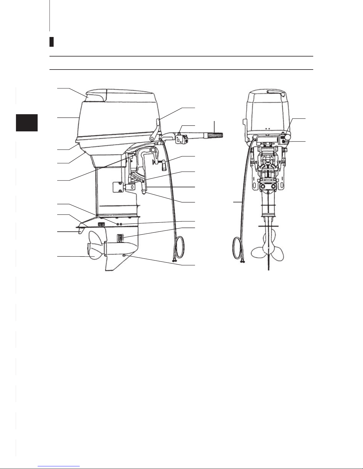
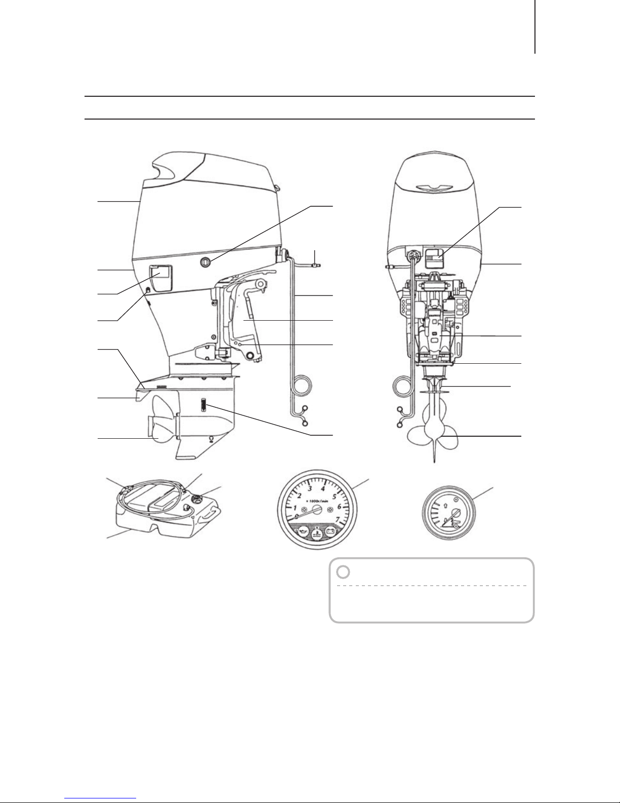
EFO / 40B2 , 50B2
NAMES OF PARTS
①
②
③
④
⑤
⑥
⑦
⑧
Tilt Handle
Top Cowl
Hook Lever
Water Check Port
Reverse Lock Lever
Water Plug
Anti-ventilation Plate
Trim Tab
⑨
⑩
○
11
○
12
○
13
○
14
○
15
○
16
Propeller
Oil Plug (lower)
Water Inlet
Oil Plug(upper)
Clamp Bracket
Thrust Rod
Clamp Screw
Throttle Grip
○
17
○
18
○
19
○
20
○
21
○
22
Stop Switch
Shift Lever
Anode
Pilot Lamp
Main Switch
Battery Cords
○
1
○
2
○
3
○
8
○
9
○
10
○
11
○
13
○
14
○
15
○
16
○
17
○
18
○
19
○
20
○
21
○
22
○
12
○
4
○
5
○
6
○
7
15
1
2
3
4
5
6
7
8
9
10
11
12
13
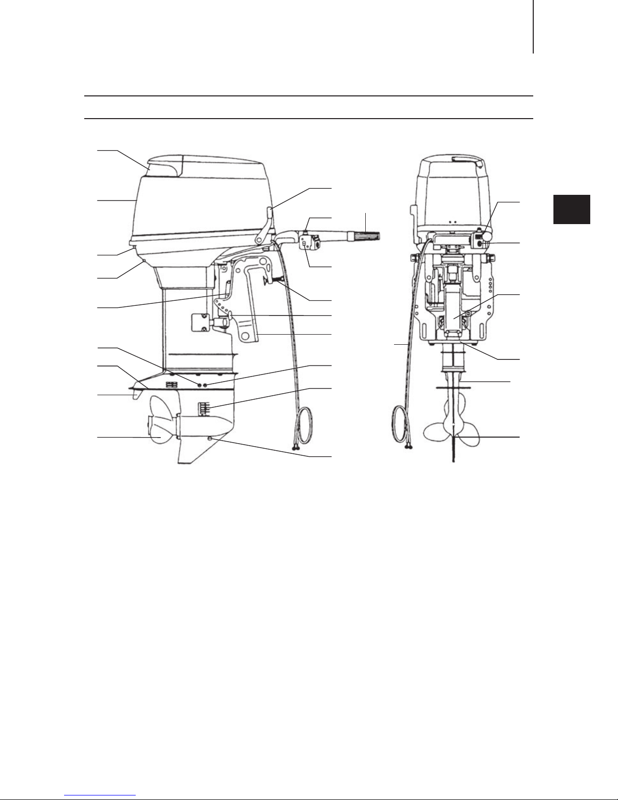
EFTO / 30B2 , 40B2 , 50B2 , W50B2
NAMES OF PARTS
○
1
○
2
○
3
○
8
○
9
○
10
○
10
○
11
○
13
○
14
○
15
○
16
○
17
○
18
○
24
○
22
○
19
○
20
○
23
○
21
○
12
○
4
○
5
○
6
○6○
12
○
7
[W50]
[W50]
①
②
③
④
⑤
⑥
⑦
⑧
Tilt Handle
Top Cowl
Hook Lever
Water Check Port
Tilt Stopper
Water Plug
Anti-ventilation Plate
Trim Tab
⑨
⑩
○
11
○
12
○
13
○
14
○
15
○
16
Propeller
Oil Plug (lower)
Water Inlet
Oil Plug(upper)
Clamp Bracket
Thrust Rod
Clamp Screw
Throttle Grip
○
17
○
18
○
19
○
20
○
21
○
22
○
23
○
24
Shift Lever
Stop Switch
Pilot Lamp
Main Switch
Battery Cords
Power Trim & Tilt
Anode
Power Trim & Tilt Switch
16
14
13
12
11
10
9
8
7
6
5
4
3
2
1
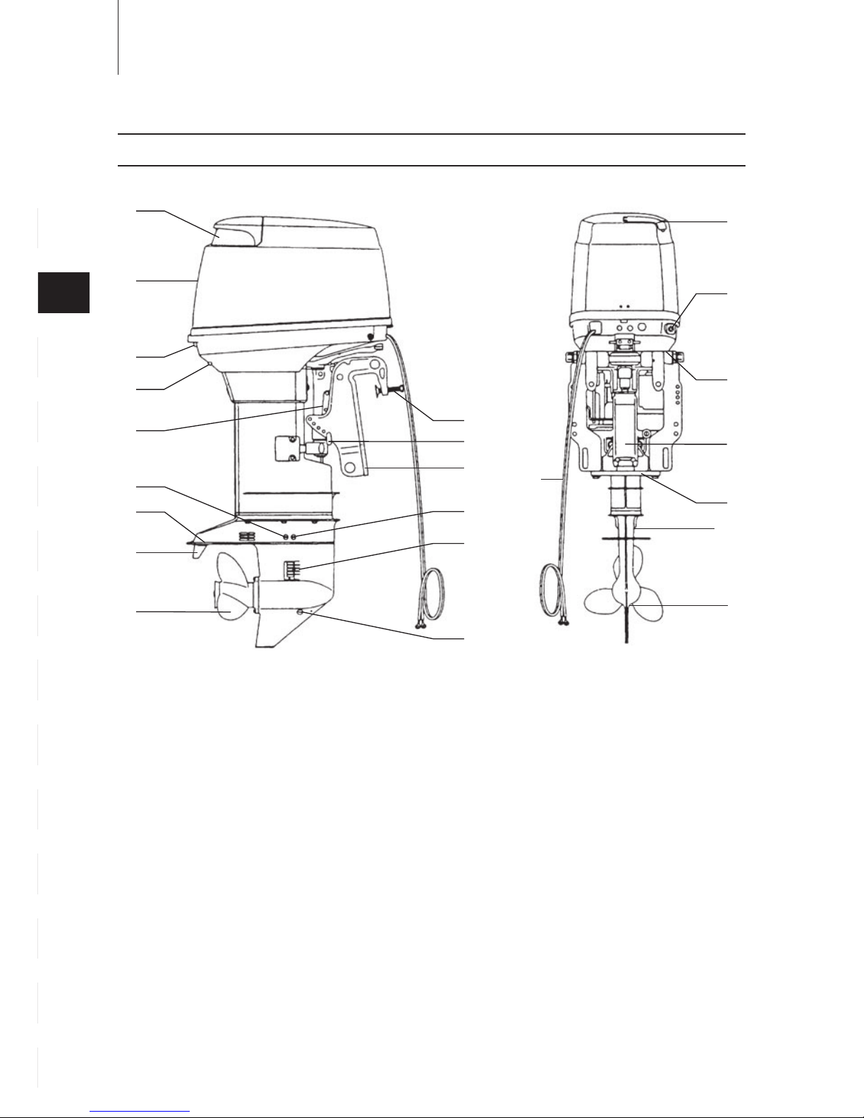
NAMES OF PARTS
EFTO / 30B2 , 40B2 , 50B2 , W50B2
①
②
③
④
⑤
⑥
⑦
⑧
Tilt Handle
Top Cowl
Hook Lever
Water Check Port
Tilt Stopper
Water Plug
Anti-ventilation Plate
Trim Tab
⑨
⑩
○
11
○
12
○
13
○
14
○
15
○
16
Propeller
Oil Plug (lower)
Water Inlet
Oil Plug(upper)
Clamp Bracket
Thrust Rod
Clamp Screw
Filler Lid
○
17
○
18
○
19
○
20
○
21
Fuel Connector
Power Trim & Tilt Switch
Battery Cords
Power Trim & Tilt
Anode
○
1
○
2
○
3
○
8
○
9
○
10
○
11
○
13
○
14
○
15
○
16
○
17
○
18
○
19
○
20
○
21
○
12
○
4
○
5
○
6
○
7
○
10
○6○
12
[W50]
[W50]
17
1
2
3
4
5
6
7
8
9
10
11
12
13
EPTO / 115A2
○
1
○
2
○
3
○
3
○
8
○
9
○
10
○
11
○
13
○
14
○
15
○
16
○
17
○
18
○
19
○
12
○
4
○
5
○
6
○
7
○
20
○
21
○
22
○
23
○
24
○
25
○
26
Remote Control Box
Remote Control Lever
Power Trim & Tilt Switch
Free Accel Lever
Main Switch
Harness B
Stop Switch
○
27
○
28
○
29
○
30
Fuel Tank
Air Vent Screw
Fuel Connector
Primer Bulb
○
31
○
32
Tachometer
Trim Meter
Note
These parts for model 115A2 are not
enclosed in the engine package.
○
27
○
30
○
29
○
28
○
31
○
32
NAMES OF PARTS
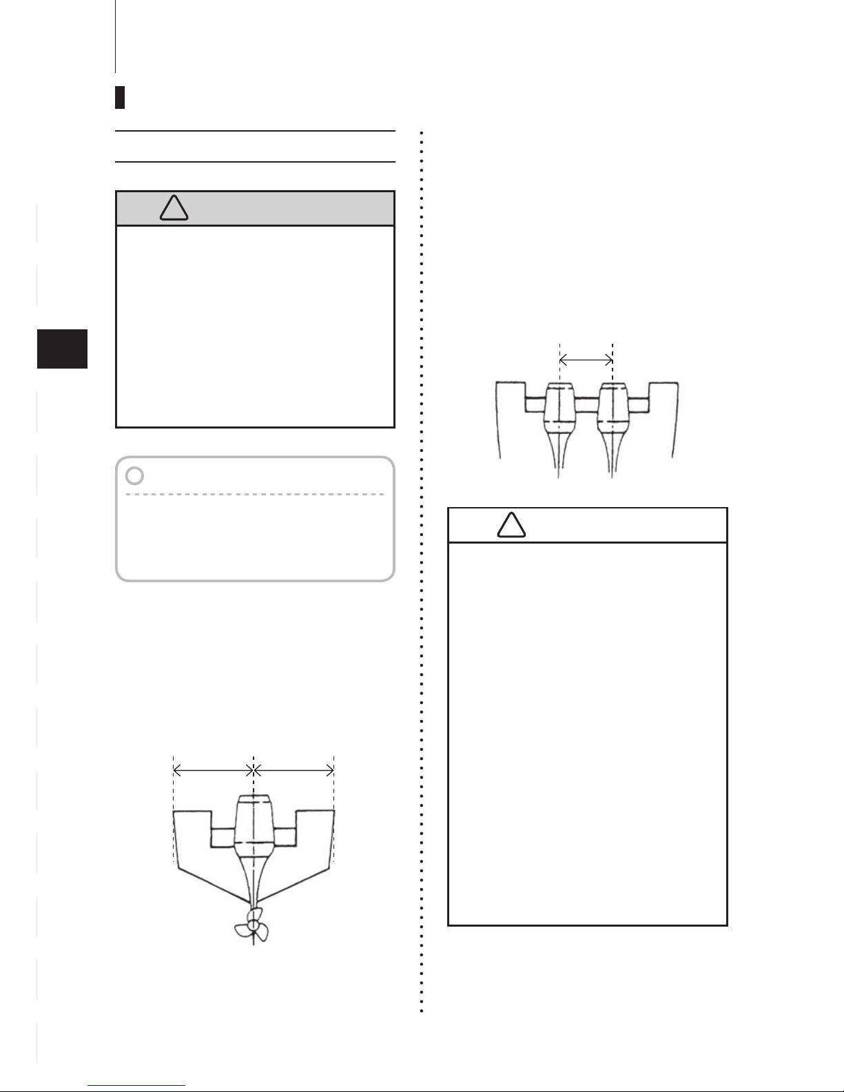
Installation
■
Single-engine Installation
Position the outboard engine at the
exact center of the stern, and mount it
using a cushioning pad or plate.
■
Twin-engine Installation
W h e n i n s t a l l i n g tw o o u t b o a r d
engines, be sure to keep an interval
of 470~660mm (for 40,50,70 and
90 models) or 700~890mm (for 115
model) between the two.
18
14
13
12
11
10
9
8
7
6
5
4
3
2
1
!
Most boats are rated and certified
in terms of their maximum allowable
horsepower, as shown on the boat’s
certification plate. Do not equip your boat
with an outboard motor that exceeds this
limit. If in doubt, contact your dealer.
Do not operate the outboard motor until
it has been securely mounted on the
boat in accordance with the instructions
below.
1. Mounting the outboard motor on boat
INSTALLATION
●
Before beginning the running test,
check that the boat with maximum
capacity loading floats on the
water in a proper attitude. Check
the position of water surface on
the driveshaft housing. If the water
surface is near the bottom cowling,
in high waves, water may enter the
engine cylinders.
●
Incorrect outboard motor mounting
height or existence of underwater
object(s), such as hull bottom
design, bottom surface conditions
or underwater accessories, can
cause water spray possibly reaching
the engine through an opening of
the bottom cowling during cruising.
Exposing engine to such conditions
for extended periods can lead to
severe engine damage.
!
A A
Note
Consult your authorized dealer to
receive the proper instructions or ask
your dealer to mount the motor as
necessary.
40 - 90 : 470 - 660mm
(18.5 - 26.0 in)
115 : 700 - 890mm
(27.6 - 35.0 in)
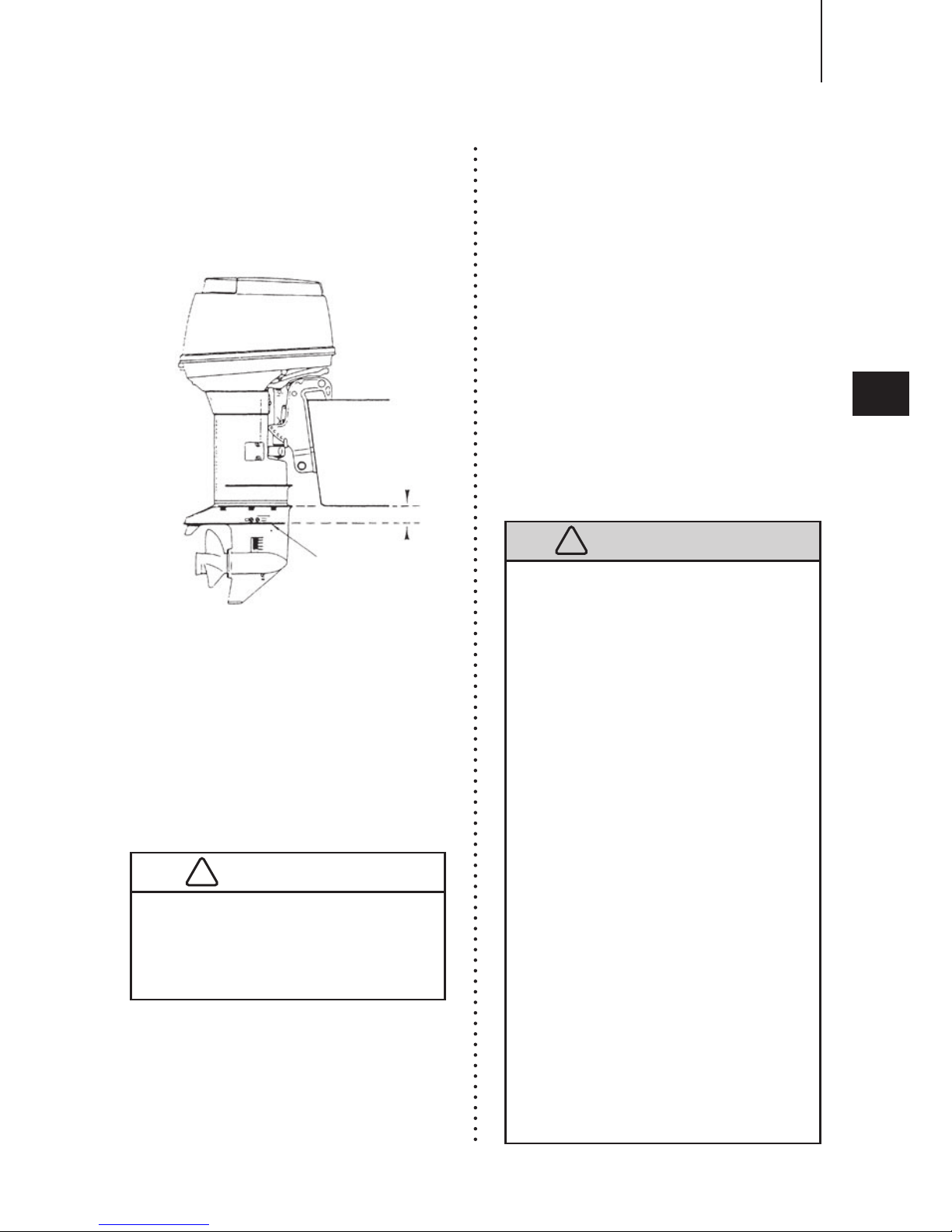
■
Transom Height
Install the engine with the Anti-ventilation
Plate at a level 10~30mm(0.4~1.2in.)
below the bottom of the boat.
■
Transom Matching
Be sure that anti ventilation plate
of the outboard is below the water
surface when running with wide open
throttle.
In case the above condition cannot
be met due to the shape of your boat,
please consult your authorized dealer.
If the hei ght di ffe ren ce exc eeds
10~30mm (0.4~1.2 in) engine power
performance is likely to be reduced as
a result of increased water resistance
to the gear case assembly.
■
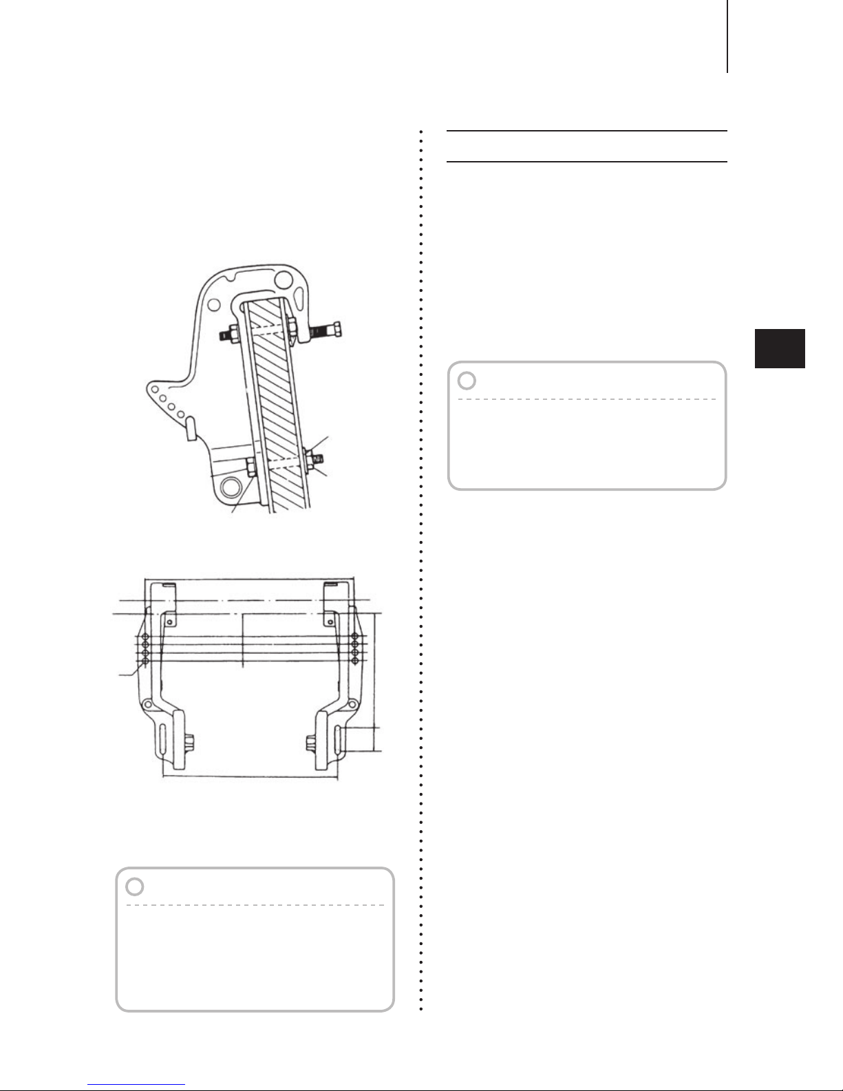
Attaching the Clamp Bracket
After positioning the Clamp Bracket, fix it
with clamp screw then drill four holes in
the transom board, matching the holes
in the Clamp Bracket. Secure the engine
with the supplied bolts (M12×105mm)
and nuts, Be sure to use the washers.
Use the larger diameter washers inside
of the transom board and use the small
diameter washers outside of the clamp
bracket.
The mounting holes may be drilled
be fo r e h a n d by refer r i n g to th e
dimensional drawing.
19
1
2
3
4
5
6
7
8
9
10
11
12
13
INSTALLATION
Anti-ventilation Plate
10~30mm (0.4~1.2 in.)
Overheating may occur if the Antiventilation Plate is at a level higher
than the bottom of the boat, as a result
of a lack of cooling water.
!
!
●
Mounting the outboard motor without
following this manual can lead to
unsafe conditions such as poor
maneuverability, going out of control
or fire disaster.
●
Loose clamp screws and/or mounting
bolts can lead to the release or
displacement of the outboard motor,
possibly resulting in lost of control
and/or serious personal injury. Be
sure that fasteners are tightened
to the specified torque (30 Nm
(3.0kgf)13ft·lb). Check the fasteners
for tightness from time to time.
●
Be sure to use outboard mounting
fasteners included in the outboard
motor package or their equivalents
in terms of size, material, quality and
strength.
Tighten fasteners to the specified
torque (30 Nm (3.0kgf)13ft·lb). Test
cruise to check if fasteners are
tightened securely.
●
Outboard motor mounting must
be performed by trained service
person(s) using lift or hoist with
sufficient capacity.
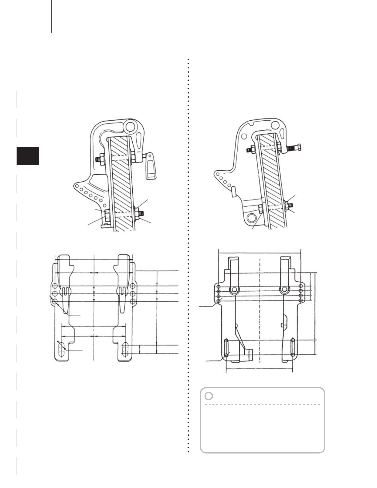
Clamp Bracket
Dimensional Drawing
■
manual tilting type
EFO 40, 50
■
with the Power Trim and Tilt type
EFTO, EPTO 30, 40, 50
20
14
13
12
11
10
9
8
7
6
5
4
3
2
1
Note
It is recommended to install upper
mounting bolts with bolt head at
inside surface of transom. Bolts with
threaded end at inside surface of
transom can cause personal injury.
INSTALLATION
Nut
Bolt
(12mm ×length 105mm)
Washer
(large diameter)
Washer
(small diameter)
ø13
ø13
234(9.21”)
39(1.54”)
222(8.74”)
248(9.76”)
26
(
1.02”
)
204(8.03”)
25(0.98”)
25(0.98”)
64(2.52”)
89(3.50”)
117(4.61”)
102(4.02”)102(4.02”)
117(4.61”)
Top of transom
Nut
Washer
(small diameter)
Washer
(large diameter)
Bolt (12mm ×length 105mm)
251
ø12.5
ø12.5
253.5
(
2.0”
)
(
10.0”
)
56
(
2.2”
)
181818
51
327
(
12.9”
)
(
9.9”
)
■
Power Trim and Tilt type
EPTO 115
A propeller must be selected so that
the engine rpm measured at wide
open throttle while cruising is within
the max. operating range;
5,150 to 5,850 rpm
Fo r ge nui ne p rope lle rs , refe r to
Propeller Table of this manual.
21
1
2
3
4
5
6
7
8
9
10
11
12
13
Notes
1. Apply sealing agent such as silicon
sealer between bolts and transom
board holes before tightening bolts.
2. Be sure to tighten mounting bolt
nuts to specified torque.
INSTALLATION
Nut
Washer
(small diameter)
Washer
(large diameter)
Bolt (12mm ×length 105mm)
251
ø13
0.5”
)
56
(
2.2”
)
254
(
10”
)
327
(
12.9”
)
(
9.9”
)
51(2”
)
Top of
Transom
17.5(0.7”
)
17.5(0.7”
)
17.5(0.7”
)
Notes
The 115 model is supplied with no
standard propeller. In other words, it
is shipped from the factory without a
propeller.
2.
Propeller Selection
30, 40, 50, 115 type
It is recommended that you consult with
your authorized dealer for installation
adjustment of the rem ote control
device.
■
Installation of the Remote Control
Cables (Box side) :
F o l l o w th e in s t r u c t i o n m a n u a l
provided with the remote control box.
■
Installation of the Remote Control
Box on your boat :
F o l l o w th e in s t r u c t i o n m a n u a l
provided with the remote control box.
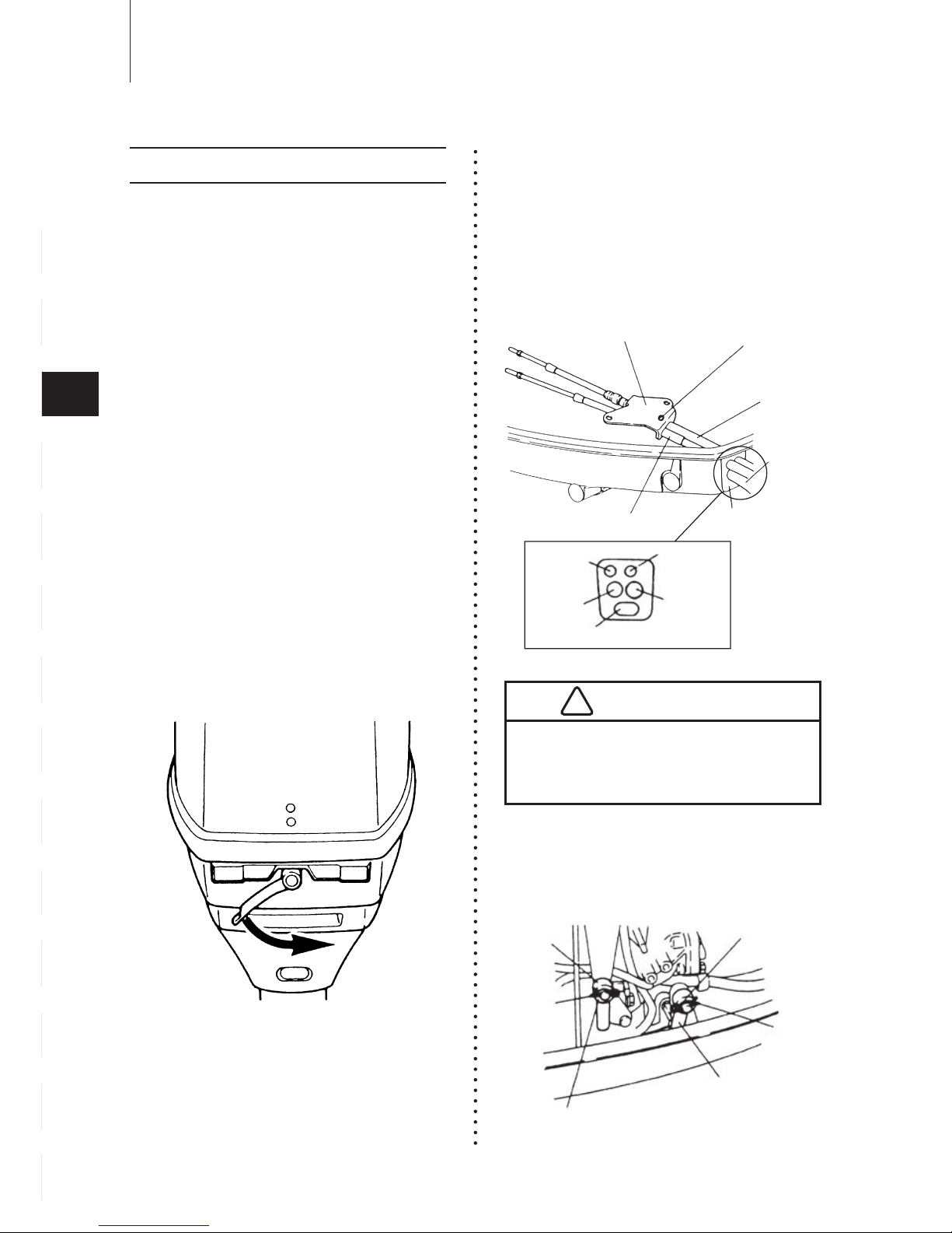
■
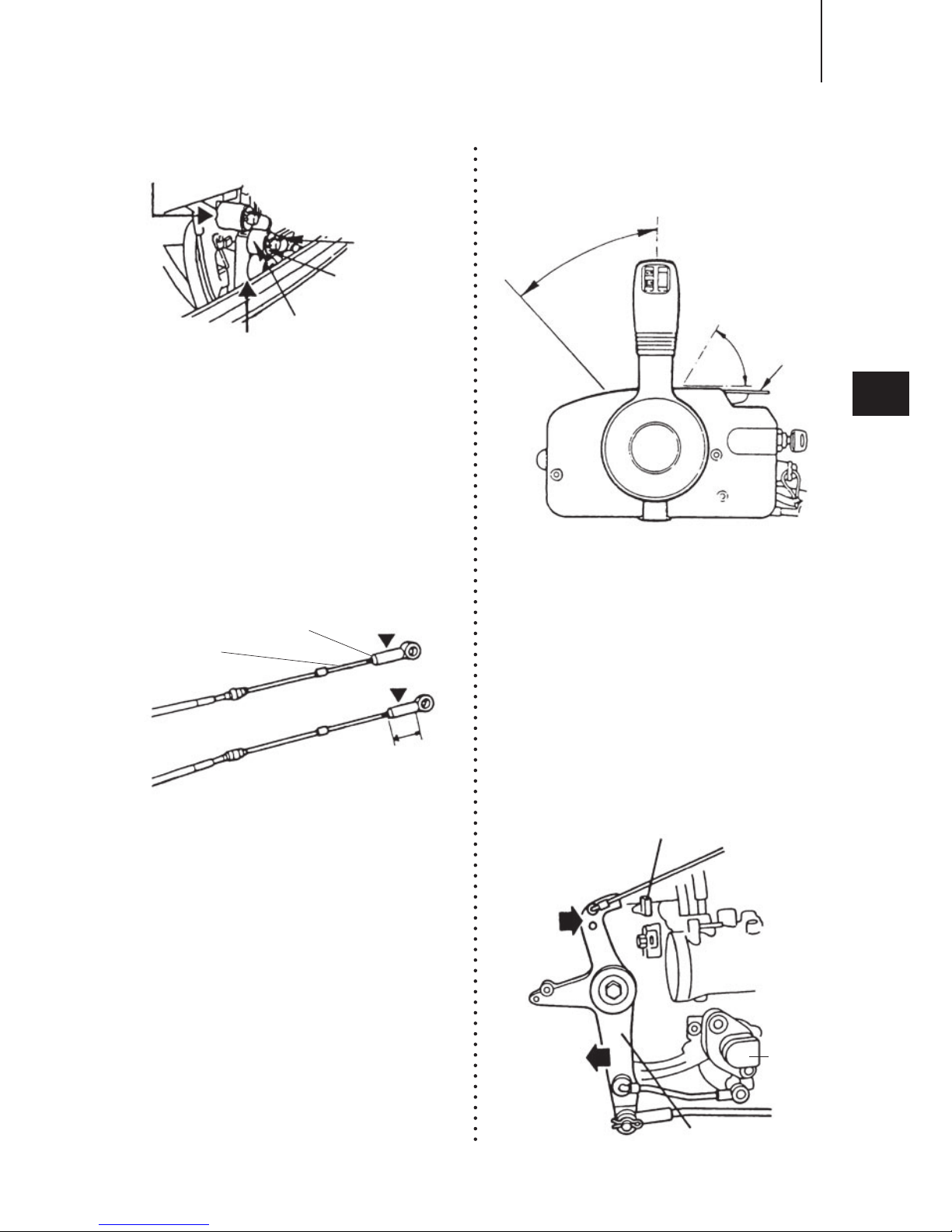
Connecting the Remote Control
Cable to the engine [40, 50] :
①
Detach the top cowl by turning the
lever.
②
Detach the bracket and set Cable
Harness B and Remote Control
Cables.
Having fixed the Remote Control
Cables to the bracket, tie them to
the bottom cowl.
③
Detach the throttle and shift cable
joints by removing the R-shaped
pins.
22
14
13
12
11
10
9
8
7
6
5
4
3
2
1
INSTALLATION
3.
Installing the remote control devices
Bracket
Screw
Throttle Cable
Cord
Harness
B
Shift Cable
Gromment
Clutch
Cable
Throttle
Cable
Meter
lead wire
Cord
Ass’
y B
Battery Cord
Throttle
Cable
Joint
R shaped
pin
Shift Cable Joint
Washer
Washer
R shaped
pin
Be careful not to loop the remote
control cables to a diameter of 406 mm
(16 inches) or less.
!
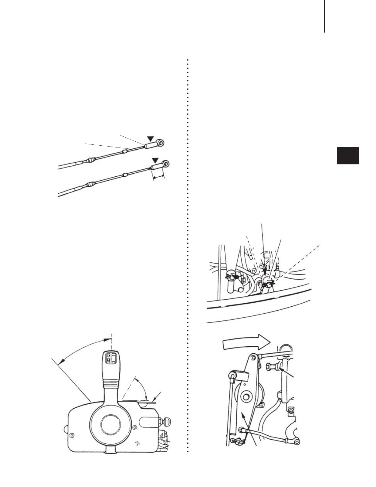
◎
Screw the tip of the remote control
cable into the cable joint up to
approx. 10mm (0.39inch), then
lock them with a lock nut. Apply
grease to the hole of the cable
joint.
④
Move the Remote Control lever
Forward, to Neutral and to Reverse
to confirm the shift is working, and
then set the lever no Neutral.
◎
Double-check that the Remote
Control Cables, the throttle cable
and shift cable have been
connected
correctly. Move the Remote Control
Lever Forward until the first engaging
point (approx 32˚). The cable which
is moved first when the lever is
turned is a shift cable. Check that
the shift lever is in Neutral and the
Free Accel lever is fully closed
when the remote control cables
have been connected.
⑤
Set the shift arm to the Neutral(N)
position and close the advancer arm
completely.
If the ad vancer ar m does no t
co nt act wit h th e st opp er, th e
throttle position sensor will be
active improperly.
◎
The advancer arm should have
contact with the stopper at neutral
position of the remote control lever.
23
1
2
3
4
5
6
7
8
9
10
11
12
13
Cable joint
Lock nut
Remote control cable
Approx. 10 mm (0.39 inch)
Free Accel
lever
Fully opened
Fully
closed
Approx
. 32
°
Shift arm
R
N
F
Advancer arm
Fully closed
Stopper
(Throttle fully
closed side)
INSTALLATION
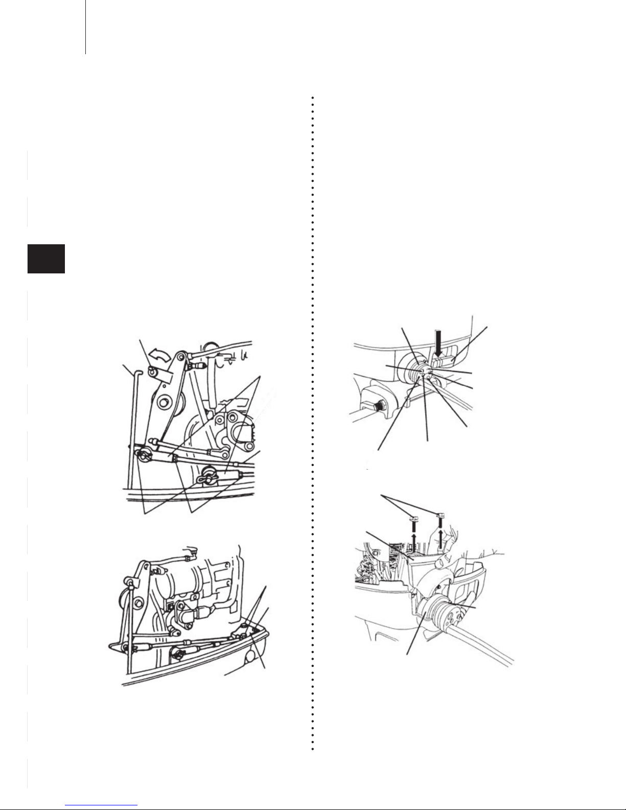
⑥
Adjust the cable joint (shift side) so
that the hole meets with the shift
arm pin, and lock the cable joint
with the nut, and insert the shift
arm pin and then secure with a
washer and R-shaped pin. Also,
adju st th e cab le jo int (throttle
side) so that the hole meets with
the advancer arm pin, and lock
the cable joint with the nut, and
insert the advancer arm pin and
then secure with a washer and
R-shaped pin.
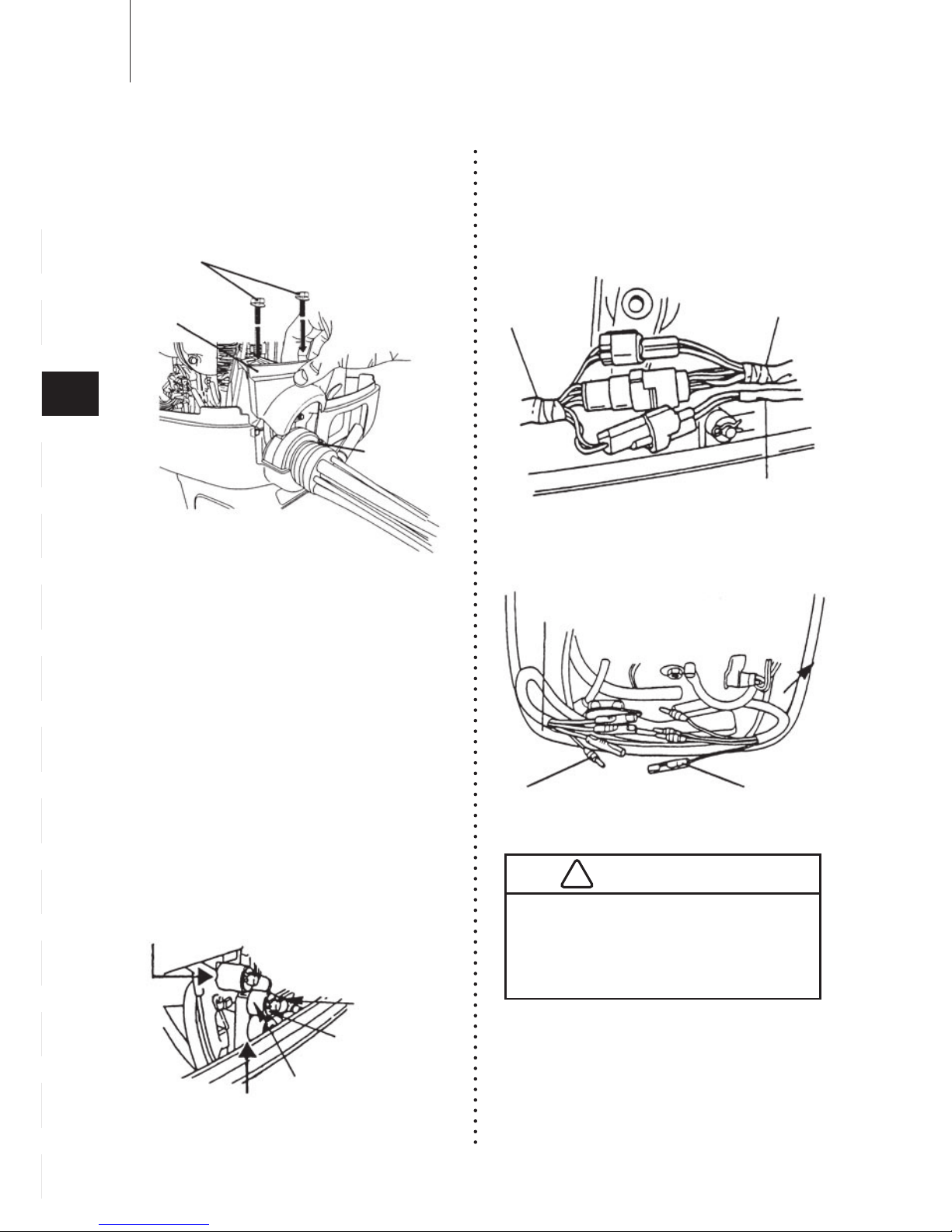
Connecting the Remote Control Cable
to the engine [115]
①
Turn the three hook levers fastening
the bottom cowl and then remove
the top cowl.
②
Remove the hose clamp fastening
the cord grommet.
Remove the bolts fastening the
cord clamp and then remove the
cord clamp and the cord grommet.
③
Detach the throttle and shift cable
Joints by removing the R-shaped
pins.
24
14
13
12
11
10
9
8
7
6
5
4
3
2
1
INSTALLATION
Throttle
Cable
Cable Joint
Rod snap
Link rod
R shaped pin Nut
Bolt
Bracket
Screw
Hole for
cord ass’y B
Hose clamp Hook lever
Hole for fuel hose
Hole for remote
control cable of
Shift side
Hole for meter
cord ass’y
Hole for
trim sender
extension cord
Hole for remote
control cable of
throttle side
Hose clamp
Cord grommet
Bolt
Cord clamp
Free Accel
lever
Fully opened
Fully
closed
Approx
. 32
°
Move the shift arm Forward, to
Neutral and to Reverse to confirm
the shift is working, and then set
the shift arm to Neutral.
◎
Screw the tip of the remote control
cable into the cable joint up to
approx.10mm(0.39inch), then lock
them with a lock nut. Here, apply
grease to the hole of the cable joint.
④
Move the Remote Control lever
Forward, to Neutral and to Reverse
to confirm the shift is working, and
then set the lever no Neutral.
◎
Double-check that the Remote
Control Cables, the throttle cable
and shift cable have been
connected
correctly. Move the Remote Control
Lever Forward until the first engaging
point (approx. 32˚). The cable which
is moved first when the lever is
turned is a shift cable. Check that
the shift lever is in Neutral and the
Free Accel lever is fully closed
when the remote control cables
have been connected.
⑤
Set the shift arm to the Neutral(N)
position and close the advancer arm
completely.
If the ad vancer ar m does no t
co nt act wit h th e st opp er, th e
throttle position sensor will be
active improperly.
◎
The advancer arm should have
contact with the stopper at neutral
position of the remote control lever.
25
1
2
3
4
5
6
7
8
9
10
11
12
13
INSTALLATION
R-shaped pin
Washer
Shift cable joint
Shift arm
Throttle cable joint
Cable joint
Lock nut
Remote control cable
Approx. 10 mm (0.39 inch)
Advancer arm
Throttle
position
sensor
Fully closed
Stopper (Throttle fully closed side)
⑥
Install the hose clamp to the cord
grommet.
Install the cord clamp.
⑦
Adjust the cable joint (shift side) so
that the hole meets with the shift
arm pin, and lock the cable joint
with the nut, and insert the shift
arm pin and then secure with a
washer and R-shaped pin. Also,
adju st th e cab le jo int (throttle
side) so that the hole meets with
the advancer arm pin, and lock
the cable joint with the nut, and
insert the advancer arm pin and
then secure with a washer and
R-shaped pin.
Connecting Cords and cable
①
Connect cable harness B and
meter lead wire to cable harness A.
②
Connect the trim sender and the
extension cable trim sensor.
26
14
13
12
11
10
9
8
7
6
5
4
3
2
1
INSTALLATION
Hose clamp
Bolt
Cord clamp
R-shaped pin
Washer
Shift cable joint
Shift arm
Throttle cable joint
Cable
Hamess A
Meter lead wire
Cable
Hamess B
Bottom cowl
Trim sender cable
Extension cable
trim sender
Do not disconnect the electric couplers
while the engine is running, as this will
damage the C.D. unit and could result
in a serious electric shock.
!
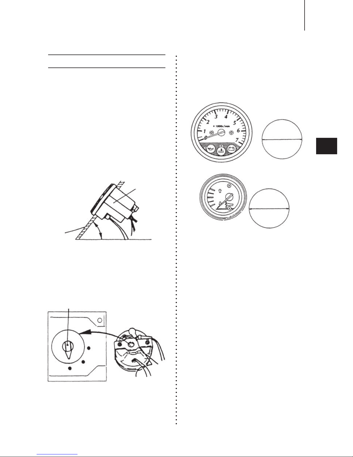
I n s t a l l th e me t e r s s e c u r e l y in
t h e d a s h b o a r d w h e r e t h e y
ca n be ea s ily rea d and a re n ot
exp os ed to water sp la shes. Th e
recommended dashboard thickness
i s 2 ~ 1 1 m m ( 0 . 0 8 ~ 0 . 4 i n . ) . Fo r
dashboards thicker than 11mm(0.4
in.), the fitting plate should be cut
accordingly. Be sure to tighten the
fitting nuts on the fitting plate evenly.
The dashboard inclination should be
50°~80°
Set the tachometer selector knob to
"4p".
Cut holes with 85mm (3.346 in.)
diamete r for the tach ome ter and
52.5mm (2.067 in.) for the trim meter.
27
1
2
3
4
5
6
7
8
9
10
11
12
13
INSTALLATION
Fitting plate
Dash
board
50°- 80°
12P
6P
4P
Selector
ø85
Tachometer
ø52.5
Trim meter
4. Installing the meters
 Loading...