

TOHATSU M 60C, M 70C, M 90A2, M 115A2, M 140A2 Owner's Manual
...
")
#,
"-
+.
2$
Έ䗴˿䢚
,/

OWNER’S
MANUAL
M 60C
M 70C
M 70CX
M 90A
M 115A
M 140A
OB No.003-11039-BAF1
2
2
2

ENOM00001-0
READ THIS MANUAL BEFORE USING THE OUTBOARD MOTOR. FAILURE TO FOLLOW THE
INSTRUCTIONS AND SAFETY PRECAUTIONS IN THIS MANUAL CAN RESULT IN SERIOUS
INJURY OR DEATH. KEEP THIS MANUAL IN A SAFE LOCATION FOR FUTURE REFERENCE.
Copyright © 2016 Tohatsu Corporation. All rights reserved. No part of this manual may be reproduced or
transmitted in any from or by any means without the express written permission of Tohatsu Corporation.

YOUR TOHATSU OUTBOARD MOTOR
ENOM00006-A
To You, Our Customer
Thank you for selecting a TOHATSU outboard motor. You are now the proud owner of an
excellent outboard motor that will service you for many years to come.
This manual should be read in its entirety and the inspection and maintenance procedures
described later in this manual should be followed carefully. Should a problem arise with the
outboard motor, please follow the troubleshooting procedures listed at the end of this
manual. If the problem persists, contact an authorized TOHATSU service shop or dealer.
Please always keep this manual together with the outboard motor as a reference to everyone who uses the outboard motor. If the outboard motor is resold, make sure the manual
is passed on to the next owner.
We hope you will enjoy your outboard motor and wish you good luck in your boating
adventures.
TOHATSU CORPORATION
ENOM00003-0
PRE-DELIVERY CHECK
Be sure that the product has been checked by an authorized TOHATSU dealer before you
take delivery.
3
4
ENOF02301-0
90
ENOF02302-0
115/140
ENOF02300-0
60/70
ENOF02371-0
ENOF02373-0
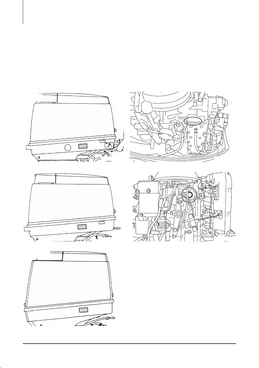
ENOM00005-A
Serial Number
In the space below, please record the outboard motor's serial number (indicated both on
the bottom cowl and on the cylinder block). The serial number will be needed when ordering parts, and when making technical or warranty inquiries.
Serial Number:
Serial Number: Date of purchase:
ENOM00007-0
NOTICE: DANGER/WARNING/CAUTION/Note
Before installing, operating or otherwise handling your outboard motor, be sure to thoroughly read and understand this Owner's Manual and carefully follow all of the instructions. Of particular importance is information preceded by the words “DANGER,”
“WARNING,” “CAUTION,” and “Note.” Always pay special attention to such information to
ensure safe operation of the outboard motor at all times.
ENOW00001-0
DANGER
Failure to observe will result in severe personal injury or death, and possibly property damage.
ENOW00002-0
WARNING
Failure to observe could result in severe personal injury or death, or property damage.
ENOW00003-0
CAUTION
Failure to observe could result in personal injury or property damage.
ENON00001-0
Note
This instruction provides special information to facilitate the use or maintenance of the outboard
motor or to clarify important points.
5


CONTENTS
1. GENERAL SAFETY INFORMATION . . . . . . . . . . . . . . . . . . . . . . . . . . . . . . .10
2. SPECIFICATIONS . . . . . . . . . . . . . . . . . . . . . . . . . . . . . . . . . . . . . . . . . . . . .12
3. PARTS NAME . . . . . . . . . . . . . . . . . . . . . . . . . . . . . . . . . . . . . . . . . . . . . . . .15
4. LABEL LOCATIONS . . . . . . . . . . . . . . . . . . . . . . . . . . . . . . . . . . . . . . . . . . .19
5. INSTALLATION . . . . . . . . . . . . . . . . . . . . . . . . . . . . . . . . . . . . . . . . . . . . . . .22
1. Mounting the outboard motor on boat . . . . . . . . . . . . . . . . . . . . . . . . . . .22
2. Remote control device installation. . . . . . . . . . . . . . . . . . . . . . . . . . . . . . .24
3. Drag link installation. . . . . . . . . . . . . . . . . . . . . . . . . . . . . . . . . . . . . . . . . .29
4. Battery installation . . . . . . . . . . . . . . . . . . . . . . . . . . . . . . . . . . . . . . . . . . .30
5. Tiller handle installation . . . . . . . . . . . . . . . . . . . . . . . . . . . . . . . . . . . . . . . 31
6. Propeller installation. . . . . . . . . . . . . . . . . . . . . . . . . . . . . . . . . . . . . . . . . . 32
6. PRE-OPERATING PREPARATIONS . . . . . . . . . . . . . . . . . . . . . . . . . . . . . . 34
1. Fuel handling . . . . . . . . . . . . . . . . . . . . . . . . . . . . . . . . . . . . . . . . . . . . . . . 34
2. Engine oil recommendation . . . . . . . . . . . . . . . . . . . . . . . . . . . . . . . . . . . .35
3. Fuel filling . . . . . . . . . . . . . . . . . . . . . . . . . . . . . . . . . . . . . . . . . . . . . . . . . 38
4. Break-In . . . . . . . . . . . . . . . . . . . . . . . . . . . . . . . . . . . . . . . . . . . . . . . . . . . 40
5. Warning system . . . . . . . . . . . . . . . . . . . . . . . . . . . . . . . . . . . . . . . . . . . . .41
7. ENGINE OPERATION . . . . . . . . . . . . . . . . . . . . . . . . . . . . . . . . . . . . . . . . . .44
Before starting . . . . . . . . . . . . . . . . . . . . . . . . . . . . . . . . . . . . . . . . . . . . . . . . 44
1. Engine oil feeding . . . . . . . . . . . . . . . . . . . . . . . . . . . . . . . . . . . . . . . . . . . 44
2. Fuel feeding . . . . . . . . . . . . . . . . . . . . . . . . . . . . . . . . . . . . . . . . . . . . . . . . 45
3. Starting the engine . . . . . . . . . . . . . . . . . . . . . . . . . . . . . . . . . . . . . . . . . .46
4. Warming up the engine . . . . . . . . . . . . . . . . . . . . . . . . . . . . . . . . . . . . . . .51
5. Forward, reverse, and acceleration . . . . . . . . . . . . . . . . . . . . . . . . . . . . . . 52
6. Stopping the engine . . . . . . . . . . . . . . . . . . . . . . . . . . . . . . . . . . . . . . . . .54
7. Steering . . . . . . . . . . . . . . . . . . . . . . . . . . . . . . . . . . . . . . . . . . . . . . . . . . .56
8. Trim angle . . . . . . . . . . . . . . . . . . . . . . . . . . . . . . . . . . . . . . . . . . . . . . . . .57
9. Tilt up and down . . . . . . . . . . . . . . . . . . . . . . . . . . . . . . . . . . . . . . . . . . . .58
10.Shallow water operation . . . . . . . . . . . . . . . . . . . . . . . . . . . . . . . . . . . . . . 61
8. REMOVING AND CARRYING THE OUTBOARD MOTOR. . . . . . . . . . . . . .62
1. Removing the outboard motor. . . . . . . . . . . . . . . . . . . . . . . . . . . . . . . . . .62
2. Carrying the outboard motor . . . . . . . . . . . . . . . . . . . . . . . . . . . . . . . . . . .62
3. Traillering . . . . . . . . . . . . . . . . . . . . . . . . . . . . . . . . . . . . . . . . . . . . . . . . . . 63
9. ADJUSTMENT . . . . . . . . . . . . . . . . . . . . . . . . . . . . . . . . . . . . . . . . . . . . . . . .65
1. Throttle grip friction . . . . . . . . . . . . . . . . . . . . . . . . . . . . . . . . . . . . . . . . . . 65
2. Remote control lever friction . . . . . . . . . . . . . . . . . . . . . . . . . . . . . . . . . . .65
3. Trim tab adjustment . . . . . . . . . . . . . . . . . . . . . . . . . . . . . . . . . . . . . . . . . 65
10. INSPECTION AND MAINTENANCE . . . . . . . . . . . . . . . . . . . . . . . . . . . . . . . 67
1. Daily Inspection . . . . . . . . . . . . . . . . . . . . . . . . . . . . . . . . . . . . . . . . . . . . . 68
2. Periodic Inspection . . . . . . . . . . . . . . . . . . . . . . . . . . . . . . . . . . . . . . . . . .73
3. Off-season storage . . . . . . . . . . . . . . . . . . . . . . . . . . . . . . . . . . . . . . . . . .83
4. Pre-season check . . . . . . . . . . . . . . . . . . . . . . . . . . . . . . . . . . . . . . . . . . . 86
5. Submerged outboard motor . . . . . . . . . . . . . . . . . . . . . . . . . . . . . . . . . . .86

6. Cold weather precautions . . . . . . . . . . . . . . . . . . . . . . . . . . . . . . . . . . . . .86
7. Striking underwater object. . . . . . . . . . . . . . . . . . . . . . . . . . . . . . . . . . . . .87
8. Operation with multiple outboard motors . . . . . . . . . . . . . . . . . . . . . . . . . 87
11. TROUBLESHOOTING . . . . . . . . . . . . . . . . . . . . . . . . . . . . . . . . . . . . . . . . . .88
12. TOOL KIT AND SPARE PARTS . . . . . . . . . . . . . . . . . . . . . . . . . . . . . . . . . .90
13. PROPELLER TABLE . . . . . . . . . . . . . . . . . . . . . . . . . . . . . . . . . . . . . . . . . . . 91
INDEX
9
1 GENERAL SAFETY INFORMATION
2. SPECIFICATIONS
3. PARTS NAME
4. LABEL LOCATIONS
5. INSTALLATION
6. PRE-OPERATING PREPARATIONS
7. ENGINE OPERATION
8. REMOVING AND CARRYING THE
OUTBOARD MOTOR
9. ADJUSTMENT
1
2
3
4
5
6
7
8
9
10.INSPECTION AND MAINTENANCE
11.TROUBLESHOOTING
12.TOOL KIT AND SPARE PARTS
13.PROPELLER TABLE
10
11
12
13
14
14

10
GENERAL SAFETY INFORMATION
ENOM00009-0
SAFE OPERATION OF BOAT
1
As the operator/driver of the boat, you are responsible for the safety of those aboard and
those in other boat around yours, and for following local boating regulations. You should
be thoroughly knowledgeable on how to correctly operate the boat, outboard motor, and
accessories. To learn about the correct operation and maintenance of the outboard motor,
please read through this manual carefully.
It is very difficult for a person standing or floating in the water to take evasive action should
he or she see a power boat heading in his/her direction, even at a slow speed. Therefore,
when your boat is in the immediate vicinity of people in the water, the outboard motor
should be shifted to neutral and shut off.
ENOW00005-0
WARNING
SERIOUS INJURY IS LIKELY IF A PERSON IN THE WATER MAKES CONTACT WITH A MOVING BOAT, GEAR HOUSING, PROPELLER, OR ANY SOLID DEVICE RIGIDLY ATTACHED TO
A BOAT OR GEAR HOUSING.
ENOM0008-A
EMERGENCY STOP SWITCH
The Emergency Stop Switch will stall the outboard motor when the stop switch lanyard is
pulled off. This stop switch lanyard has to be attached to the operator of the outboard
motor to minimize or prevent injuries from the propeller in case the operator falls overboard.
It is operator’s responsibility to use the Emergency Stop Switch Lanyard.
ENOW00004-A
WARNING
Accidental activation of the Emergency Stop Switch (such as the tether being pulled out in
heavy seas) could cause passengers to lose their balance and even fall overboard, or it
could result in loss of power in heavy seas, strong currents, or high winds. Loss of control
while mooring is another potential hazard.
To minimize accidental activation of the Emergency Stop Switch, the 500 mm (20 inch.) stop
switch lanyard is coiled and can extended to a full 1300 mm (51 inch.).
ENOM00800-A
PERSONAL FLOATATION DEVICE
As the operator/driver and passenger of the boat, you are responsible to wear a PFD (Personal Floatation Device) while on the boat.

GENERAL SAFETY INFORMATION 11
ENOM00010-0
SERVICING, REPLACEMENT PARTS & LUBRICANTS
We recommend that only an authorized service shop perform service or maintenance on
this outboard motor. Be sure to use genuine parts, genuine lubricants, or recommended
lubricants.
ENOM00011-A
MAINTENANCE
As the owner of this outboard motor, you should be acquainted with correct maintenance
procedures following maintenance section of this manual (See page 67). It is the operator's responsibility to perform all safety checks and to ensure that all lubrication and maintenance instructions are complied with for safe operation. Please comply with all
instructions concerning lubrication and maintenance. You should take the engine to an
authorized dealer or service shop for periodic inspection at the prescribed intervals.
Correct periodic maintenance and proper care of this outboard motor will reduce the
chance of problems and limit overall operating expenses.
Carbon Monoxide Poisoning Hazard
Exhaust gas contains carbon monoxide, a colorless and odorless gas which can be fatal if
inhaled for any length of time.
Never start or operate the engine indoors or in any space which is not well ventilated.
Gasoline
Gasoline and its vapors are very flammable and can be explosive. Use extreme care when
handling gasoline. You should be thoroughly knowledgeable on how to correctly handle
gasoline by reading this manual.
1
12
SPECIFICATIONS
ENOM00810-A
MODEL FEATURE
Model M60C M70C M70CX
Ty pe EPTO MFG EPTO MFG
2
Transom heights
Tiller handle z z
Remote control z z
Power tilt z z
Gas-assisted tilt z z
Mnual tilt
Model M90A2 M115A2 M140A2
Ty pe EPTO EPTO EPTO
Transom heights
Tiller handle
Remote control z z z
Power tilt z z z
Gas-assisted tilt
Mnual tilt
(z) These models can be purchased with remote rigging kit or multi function tiller handle.
ENOM00811-B
MODEL NAME EXAMPLE
M140A2 EPTOL
M 140 A 2 E P T O L
Model
descrip-
tion
M (X) = Two
stroke
F= Four stroke
D= Two stroke
DI
S
L z z z z
UL z z z
S
L z z z
UL z z z
Horse
power
Product
generation
A and up
-
Miner
change
2 and
up
Starter
system
E=
Electrical
start
M=
Manual
start
Steering
system
P=Remote
controlࠉ
(Pleasure)
F=Tiller handle
(Fisher)
Tilt
system
T= Power
trim&tilt
G=
Gas assist
Blank=
Manual tilt
Lubrication
system
Oil auto-mxing
Blank=
Oil Pre-mixing
Shaft length
O=
S= Short 15 in
L= Long 20 in
UL=
Ultra long 25 in

ENOM01721-0
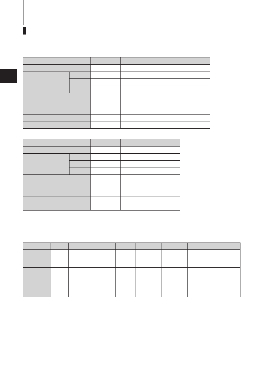
60C/70C EPTO, 70C/70CX MFG
SPECIFICATIONS 13
Item MODEL
Overall Length mm (in) Approx. 720 (28.3) Approx. 1280 (50.4)
Overall Width mm (in) Approx. 360(14.2)
Overall Height
Transom Height
Weight
Output kW (Hp) 60C: 44 (60) / 70C/70CX: 52 (70)
Max. Operating Range rpm 5150-5850
Idle Speed in Neutral Gear
Trolling Speed in Forward Gear
Engine Type 2-Stroke
Number of Cylinder 3
Bore x Stroke mm (in) 74 x 72.7 (2.91 x 2.86)
Piston Displacement mL (Cu in) 938 (57.23)
Exhaust System Through hub exhaust
Cooling System Forced water cooling
Lubrication System
Starting System Electric starter motor
Ignition System Flywheel Magneto C.D. Ignition
Spark Plugs NGK B8HS-10 or BR8HS-10
Alternator 12V, 130W (12V, 11A)
Trim Position
Fuel
Fuel Tank Capacity L (US gal) 25 (6.6)
Engine Oil Genuine motor oil or recommended one (TCW-III)
Fuel : Engine oil Mxing Retio
Gear Oil
Gear Reduction Ratio 2.33 (12 : 28)
L mm (in)
UL mm (in)
L mm (in)
UL mm (in)
L kg (lb) 115 (254) 105.5 (233)
UL kg (lb)
rpm 900
rpm
Unleaded regular gasoline pump posted 87 Octane (research octane rating of 91)
mL (fl, oz)
60C/70C
EPTO
1415 (55.7) 1455 (57.3)
1542 (60.7) 1582 (62.3)
517 (20.4)
644 (25.4)
117.5 (259) 108 (238)
750
Auto-oil mixing
25
120 : 1-50 : 1 50 : 1
Genuine Gear Oil or API GL5, SAE #80 to #90, approx. 900 (30.4)
70C/70CX
MFG
Engine oil mixed gasoline
Manual
Remark: Specifications subject to change without notice.
Tohatsu outboard is power rated in accordance with ISO8665 (propeller shaft output).
2

SPECIFICATIONS14
ENOM01722-0
90A2, 115A2/140A2 EPTO
Item MODEL 90A2 EPTO 115A2 EPTO 140A EPTO
2
Overall Length mm (in) Approx. 690 (27.2) Approx. 747 (29.4)
Overall Width mm (in) Approx. 360 (14.2) Approx. 390 (15.4)
Overall Height
Transom Height
Weight
Output kW (Hp) 66 (90)
Max. Operating Range rpm 5150-5500
Idle Speed in Neutral Gear
Trolling Speed in Forward Gear
Engine Type 2-Stroke
Number of Cylinder 3
Bore x Stroke mm (in) 86 x 72.7 (3.39 x 2.86)
Piston Displacement mL (Cu in) 1267 (77.3)
Exhaust System Through hub exhaust
Cooling System Forced water cooling
Lubrication System
Starting System Electric starter motor
Ignition System Flywheel Magneto C.D. Ignition
Spark Plugs NGK B8HS-10 or BR8HS-10
Alternator 12V, 130W (12V, 11A)
Trim Position 2
Fuel
Fuel Tank Capacity L (US gal) 25 (6.6)
Engine Oil Genuine motor oil or recommended one (TCW-III)
Fuel : Engine oil mixing Ratio
Gear Oil
Gear Reduction Ratio 1.85 (13 : 24)
Remark: Specifications subject to change without notice.
Tohatsu outboard is power rated in accordance with ISO8665 (propeller shaft output).
L mm (in) 1435 (56.5) 1560 (61.4)
UL mm (in) 1562 (61.5) 1687 (66.4)
L mm (in) 517 (20.4)
UL mm (in)
L kg (lb) 135 (298) 164 (362)
UL kg (lb) 137.5 (303) 166.5 (367)
rpm 900
rpm 750
644 (25.4
85 (115) 103 (140)
5200-5700
1768 (107.9)
Auto oil mixing
12V, 330W (12V, 27.5A)
Unleaded regular gasoline pump posted 87 Octane (research octane rating of 91)
120 : 1-50 : 1
mL (fl. oz)
Genuine Gear Oil or API GL5, SAE #80 to #90, approx. 900 (30.4
4
PARTS NAME
ENOM01700-0
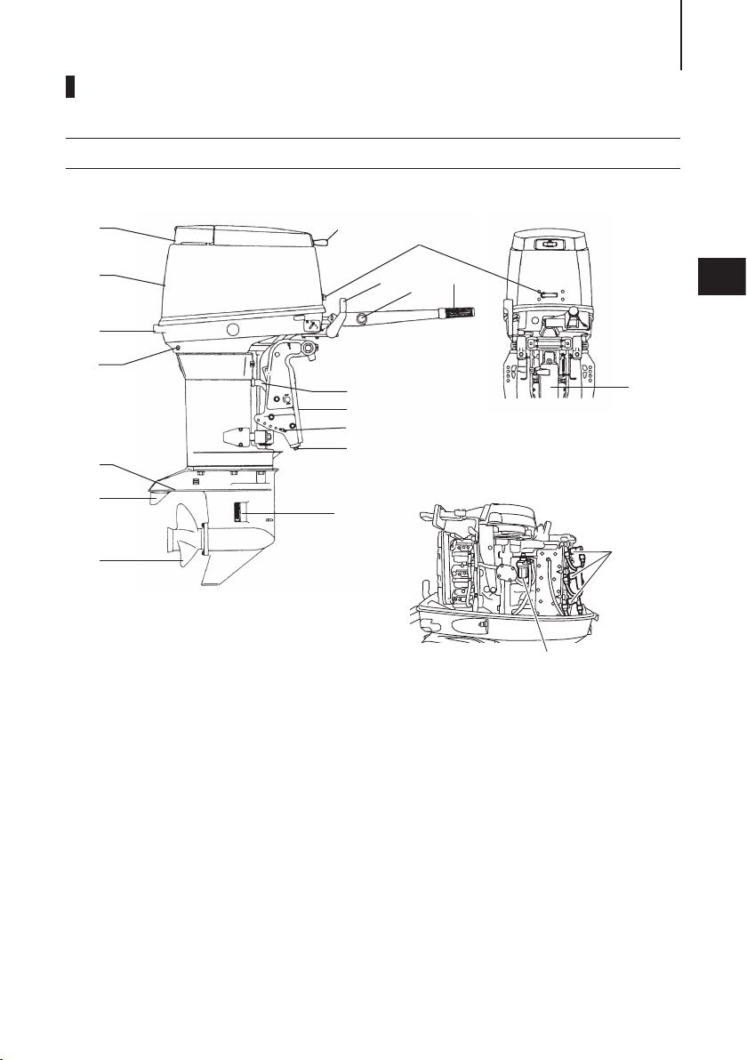
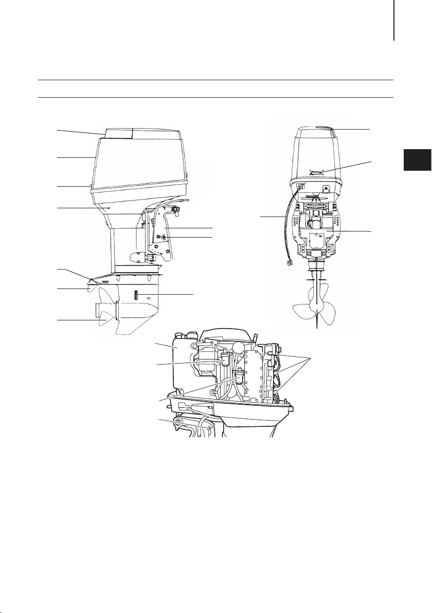
70 MFG
15
1
2
16
14
3
15
13
3
3
4
5
17
10
11
12
6
7
9
18
8
19
1
Tilt Handle
2
Top C owl
3
Hook Lever
4
Water Check Port
5
Reverse Lock Lever
6
Anti-ventilation Plate
7
Tri m Tab
8
Propeller
9
Water Inlet
10
Clamp Bracket
11
Thrust Rod
12
Anode
13
Throttle Grip
14
Shift Lever
15
Stop Switch
16
Starter Handle
17
Gas Asistant
18
Spark Plug
19
ENOF02303-0
Fuel filter
PARTS NAME16
ENOM01701-0
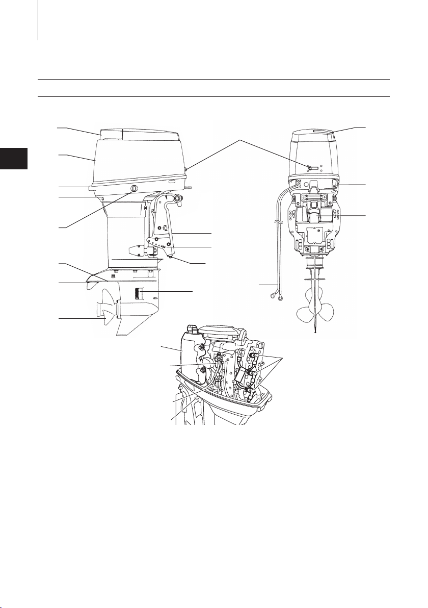
60/70 EPTO
3
1
3
16
2
3
14
4
12
5
10
11
6
7
13
9
15
8
17
20
18
19
21
ENOF02304-0
1
Tilt Handle
2
Top C owl
3
Hook Lever
4
Water Check Port
5
PTT Switch
6
Anti-ventilation Plate
7
Tri m Tab
8
Propeller
9
Water Inlet
10
Clamp Bracket
11
Thrust Rod
12
Power Trim & Tilt
13
Anode
14
Fuel Connector
15
Battery Cords
16
Filler Lid
17
Oil Tank
18
Fuel Filter
19
Oil Filter
20
Spark Plug
21
Tilt Stopper
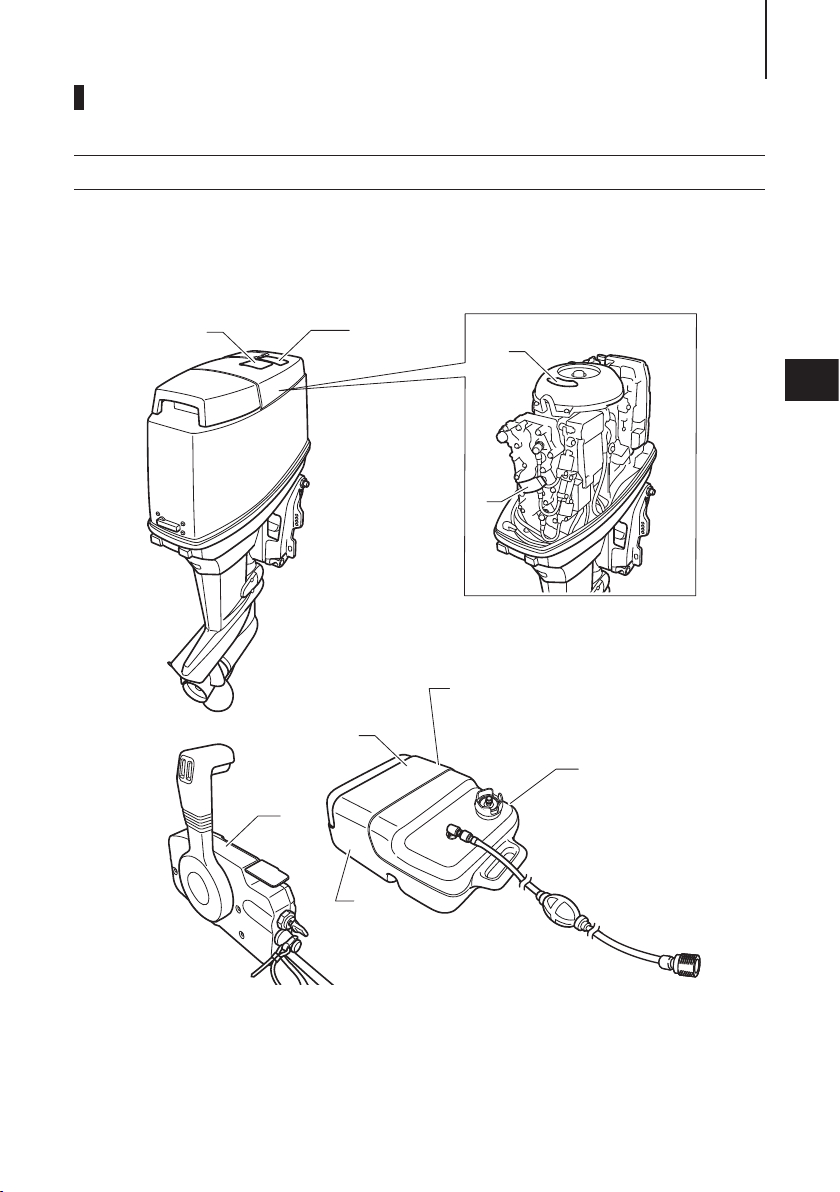
ENOM01702-0
2
3
4
7
8
5
6
10
9
2
12
13
11
17
14
15
16
18
1
ENOF02305-0
90, 115/140 EPTO
PARTS NAME 17
3
1
Top C owl
2
Hook Lever
3
Water Check Port
4
Gear Case
5
Anti-ventilation Plate
6
Tri m Tab
7
Propeller
8
Water Inlet
9
Clamp Bracket
10
Manual Valve (Port side)
11
Power Trim & Tilt
12
Battery Cords
13
Filler Lid
14
Oil Tank
15
Fuel Filter
16
Oil Filter
17
Spark Plug
18
Tilt Stopper
PARTS NAME18
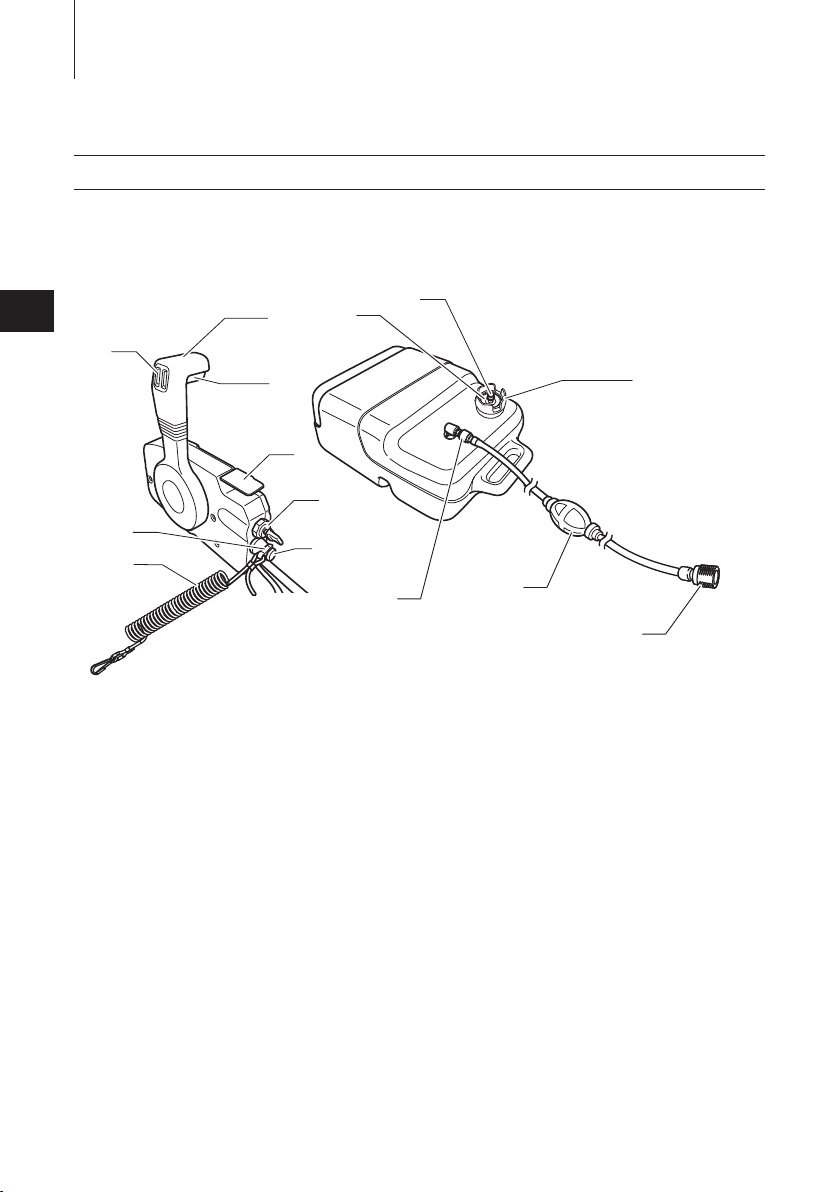
ENOM00822-0
Remote control box & Fuel tank
3
3
7
8
1
2
10
9
11
4
5
6
14
13
12
1
Control Lever
2
Neutral Lock Arm
3
PTT Switch
4
Free Throttle lLver
5
Main Switch
6
Stop Switch
7
Stop Switch Lock
8
Stop Switch Lanyard
9
Fuel Gauge
10
Air Vent Screw
11
Fuel Tank Cap
12
Fuel Connector (Engine Side)
13
Primer Bulb
14
Fuel Connector (Fuel Tank Side)
ENOF00127-E
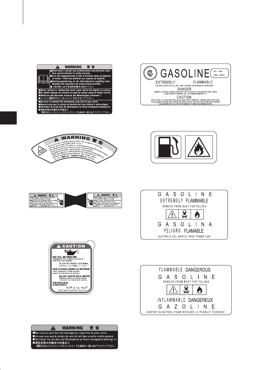
LABEL LOCATIONS
ENOM00019-A
Warning label locations
19
4
1
2
4
3
7
6
8
5
9
ENOF02374-0
LABEL LOCATIONS20
ENOF00005-M
ENOF00005-F
1.
Warning label urge to read the owner’s
manual .
6.
Warning regarding gasoline. (See
page 34)
4
3C7-72180-3
2.
Warning regarding rotating object.
3C7-72182-2
3.
Warning regarding high voltage.
3C8-72181-0
4.
Warning regarding engine oil replenishment.
7.
Warning regarding gasoline (See
ENOF00005-E
page 34).
8.
Warning regarding gasoline (See
ENOF00005-L
page 34).
9.
Warning regarding gasoline (See
page 34).
For RC model
3T1-72043-0
5.
Warning label regarding stop switch
lanyard.
ENOF00005-D
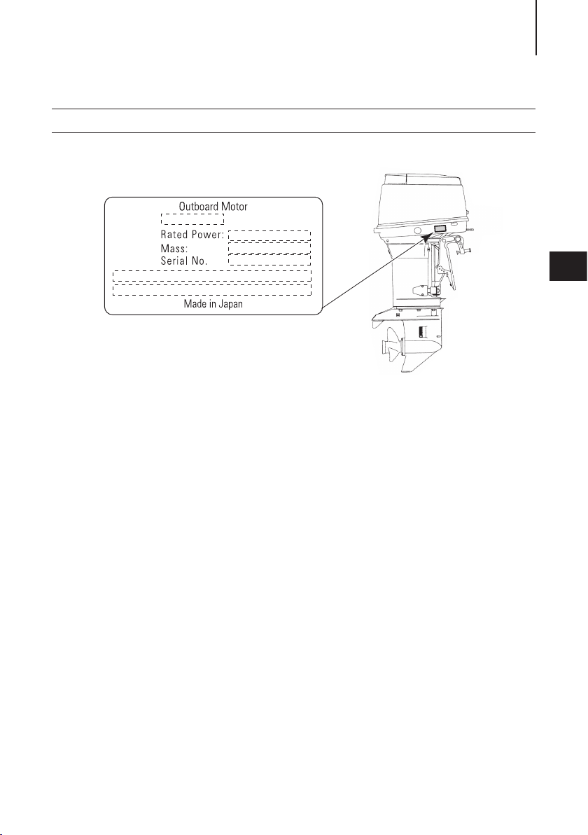
ENOM01001-A
ENOF02306-0
1)
2)
3)
4)
5)
6)
Serial number label locations
1. Model code(Model name)
2. Rated power
3. Dry mass weight
4. Serial No.
5. Manufacture name
6. Manufacture address
LABEL LOCATIONS 21
4
22
ENOF02387-0
INSTALLATION
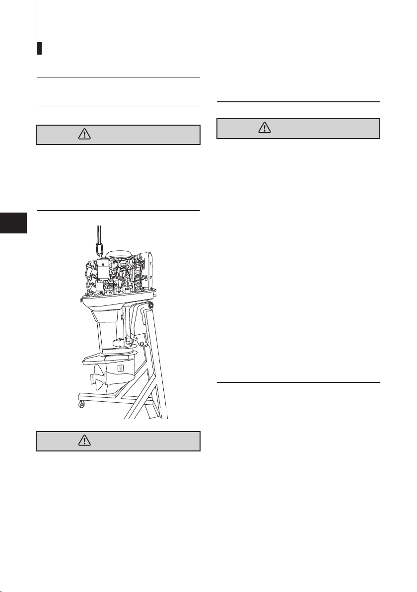
ENOM00024-A
1. Mounting the outboard motor on
boat
ENOW00006-B
WARNING
Before installing the outboard motor on the
boat, hang the outboard motor with the
hoist or equivalent device by attaching the
engine hanger to the outboard. Use the
hoist with allowable load is 250 kg (550 lbs)
or above.
5
Do not operate the outboard motor until it
has been securely mounted on the boat in
accordance with the instructions below.
ENOW00009-0
WARNING
z Mounting the outboard motor without
following this manual can lead to unsafe
conditions such as poor maneuverability, lack of control or fire.
z Loose clamp screws and/or mounting
bolts can lead to the release or displacement of the outboard motor, possibly
resulting in lost of control and/or serious
personal injury. Be sure that fasteners
are tightened to the specified torque (30
Nm (3.0 kgf) 13 ft-lb). Check the fasteners for tightness from time to time.
z Be sure to use outboard mounting fas-
teners included in the outboard motor
package or their equivalents in terms of
size, material, quality and strength.
Tighten fasteners to the specified torque
(30 Nm (3.0 kgf) 13 ft-lb). Test cruise to
check if fasteners are tightened
securely.
z Outboard motor mounting must be per-
formed by trained service person(s)
using lift or hoist with sufficient capacity.
ENOW00006-0
WARNING
Most boats are rated and certified in terms
of their maximum allowable horsepower,
as shown on the boat’s certification plate.
Do not equip your boat with an outboard
motor that exceeds this limit. If in doubt,
contact your dealer.
Outboard motor mounting must be performed by trained service person(s) using
lift or hoist with sufficient capacity.
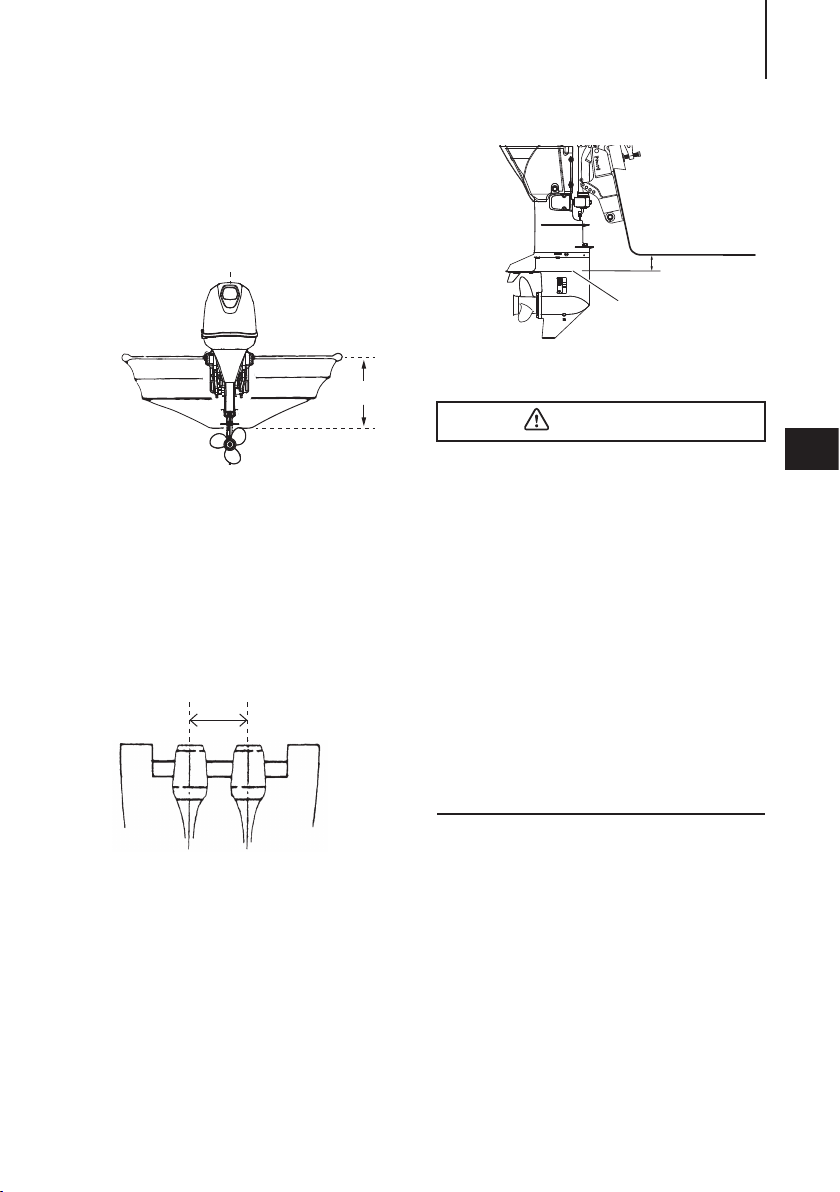
ENOM00025-A
1
2
10−30 mm
(0.4−1.2 in)
ENOF01706-B
Position ... Above keel line
Single-engine Installation
Set engine at center of boat.
1
2
ENOF01141-0
1. Center of boat
2. Boat transom
ENOM01201-0
Twin-engine Installation
When installing two outboard engines, be
sure to keep an interval of approximately
580 mm (22.8 in) between the two.
1
INSTALLATION 23
1. Bottom of hull
2. Anti ventilation plate
ENOW00007-0
CAUTION
z Before beginning the running test, check
that the boat with maximum capacity
loading floats on the water in a proper
attitude. Check the position of water
surface on the driveshaft housing. If the
water surface is near the bottom cowling, in high waves, water may enter the
engine cylinders.
z Incorrect outboard motor mounting
height or existence of underwater
object(s), such as hull bottom design,
bottom surface conditions or underwater accessories, can cause water spray
possibly reaching the engine through an
opening of the bottom cowling during
cruising. Exposing the engine to such
conditions for extended periods can
lead to severe engine damage.
5
ENOF01823-0
1. Approx 580 mm (22.8 in)
ENOM00026-0
Transom matching
Be sure that the anti ventilation plate of the
outboard motor is 10–30 mm (0.4–1.2 in)
below the bottom of hull.
If the above condition cannot be met due
to the shape of the bottom of your boat,
please consult your authorized dealer.
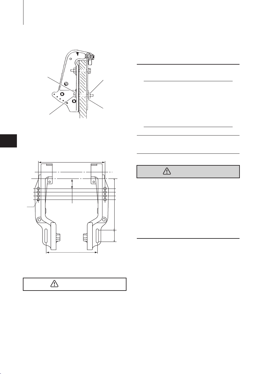
ENOM00830-A
Mounting bolts
Power trim and tilt type
1. To attach the outboard motor to the
boat, use the bolts to secure the outboard motor brackets on transom
board.
INSTALLATION24
2
1
1. Bolt (12 mm × length 105 mm)
2. Washer (small diameter)
3. Washer (large diameter)
5
4. Nut
ø
13
1. Top of t ran som
327 (12.9')
51 (2')
17.5 (0.7')
17.5 (0.7')
17.5 (0.7')
251 (9.9')
4
3
ENOF02317-0
1
ENOF02318-0
254
(10')
56
(2.2)
z Tighten the bolts sufficiency, otherwise
falling down of outboard could be happened.
ENON00003-0
Notes
1. Apply sealing agent, such as silicone
sealed between the bolts and the transom board holes before tightening the
bolts.
2. Be sure to tighten the mounting bolt
nuts to the specified torque.
(30 Nm (3.0 kgf) 13 ft-lb)
ENOM00840-A
2. Remote control device
installation
ENOW00944-A
WARNING
When using other than Tohatsu’s genuine
remote control box, DO NOT select the one
without neutral safety switch that prevents
in-gear start.
Use of remote control box without neutral
safety switch can allow start of engine with
gear at other than neutral shift, potentially
leading passengers to falling or causing
passenger to be thrown overboard.
It is recommended that you consult w i t h
your authorized dealer for installation
adjustment of the remote control device.
ENOW00008-A
CAUTION
z Mounting bolts should be installed with
the bolt head at inside surface of the
transom. Mounting bolts installed with
the threaded end at the inside surface of
the transom can cause personal injury.
INSTALLATION 25
3
1, 2
ENOF00841-0
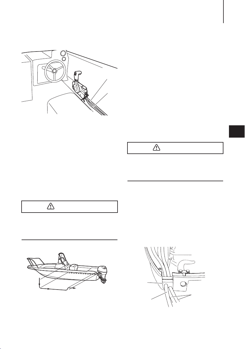
ENOM00850-0
Remote control box location
1. Shift cable
2. Throttle cable
3. Cord assembly B
Install the remote control box in a position
where it is easy to reach and operate the
controls.
Make sure there are no obstacles that can
interfere with the operation of the remote
control cable.
ENOM00850-0
Remote control cable length
ENOW00100-A
CAUTION
Be careful not to loop the remote control
cables to a diameter of 406 mm (16 inches)
or less. Otherwise, it affects the service life
of the cable.
Prepare a cable that is 300-450mm (11.8-
17.7in) longer than the measured distance.
Temporarily pull the cable along the
intended cable route to check its length is
sufficient.
Connect the remote control cable to the
engine, then run the cable to the remote
control box, making sure it is not sharply
bent, too taut and free from obstructions
that could interfere with steering.
ENOM01703-0
Installation of the Remote Control
Cable (engine side) and the Cord
Assembly (Wiring Harness) :
ENOW00100-A
CAUTION
Be careful not to loop the remote control
cables to a diameter of 406 mm (16 inches)
or less. Otherwise, it affects the service life
of the cable.
ENOM01704-0
60/70
1. Detach the bracket and set cord
assembly B and the remote control
cables in position.
After fixing the remote control cables to
the bracket, re-secure the bracket to
the lower cowl.
5
ENOF00842-0
Measure the distance from the remote
control box to the outboard motor where
the remote control cable should be routed.
1
2
1. Cord grommet
2. Cord assembly B
3. Battery cord
3
ENOF02308-0
INSTALLATION26
1
4
3
6
2
1. Remote control grommet
2. Battery cord grommet
3. Clutch cable
4. Extension cord
5
5. Throttle cable
6. Cord assembly B
7. Battery cord
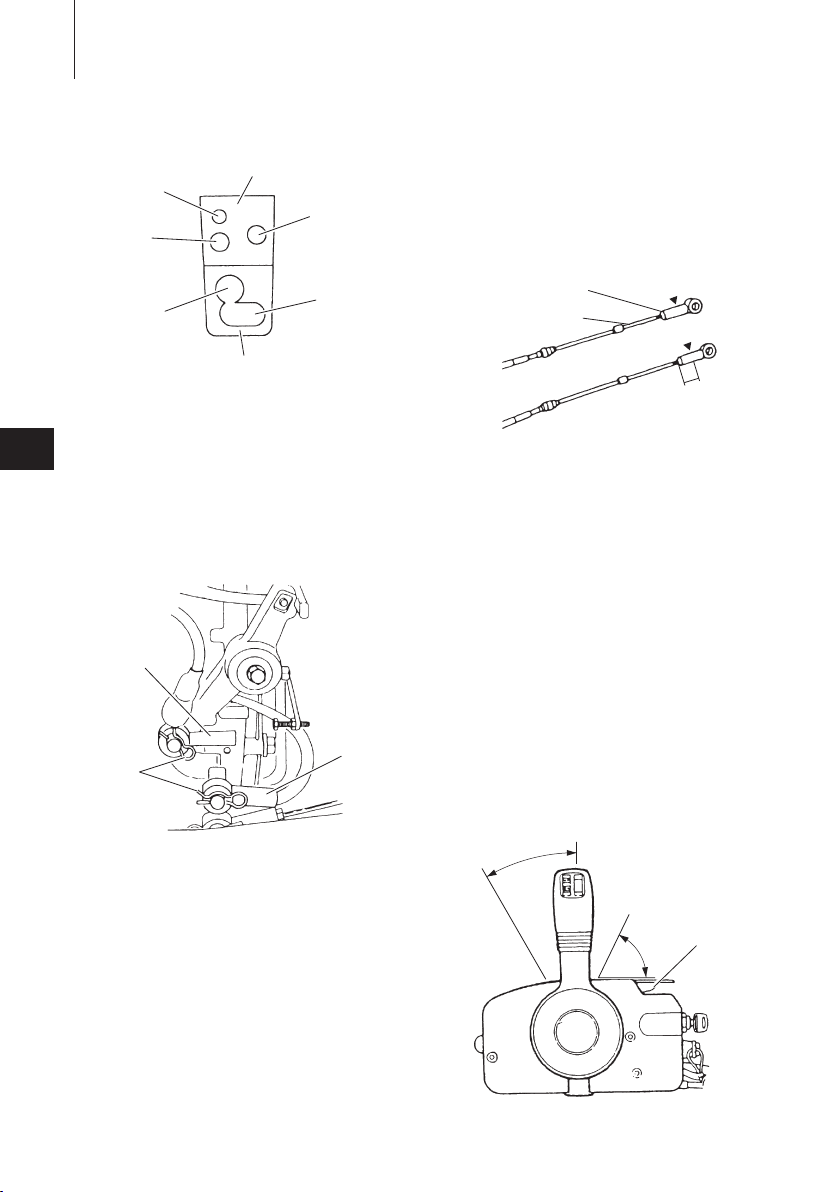
2. Detach the throttle and shit cable joints
by removing the R-pins.
2
1
1. R-pin
2. Throttle cable joint
3. Shift cable joint
Screw the tip of the remote control
cable into the cable joint up to approx.
10 mm (0.39 inch), then lock them with
a lock nut. Here, apply grease to the
hole of the cable joint.
5
7
ENOF02309-0
3
ENOF02310-0
3. Move the remote control lever to the
“FORWARD” “NEUTRAL” and
“REVERSE” positions to confirm that
the shift is working properly, then set
the lever to “NEUTRAL”.
2
3
1
3
4
ENOF02311-0
1. Remote control cable
2. Lock nut
3. Cable joint
4. Approx. 10 mm (0.39 in)
4. Double-check that the remote control
cables (i.e., the throttle cable and shift
cable) have been connected correctly.
Move the remote control lever forward
to the first point at which it engages
(approx. 32°). The cable which moves
first when the lever is turned should be
the shift cable. Check that the shift
lever is in “NEUTRAL” position and that
the free throttle lever is fully closed
when the remote control cables have
been connected.
4
2
1
3
1. Free throttle lever
2. Fully opend
ENOF02312-0
INSTALLATION 27
3. Fully closed
4. Approx. 32
°
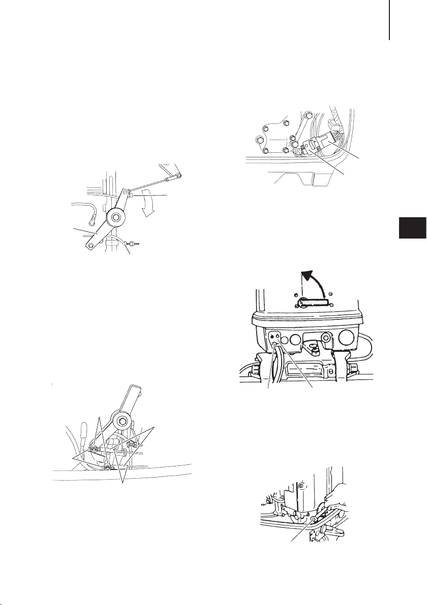
* The advancer arm on the engine should
be contact with the stopper of the cylinder crank case assembly so that the
throttle valve of the carburetor is to be
fully closed condition.
2
1
ENOF02313-0
3
1. Advancer arm
2. Stopper (Throttle fully closed side)
3. Stopper (Throttle fully opend side)
5. Adjust the cable joints until the hole of
each is aligned with the advancer arm
pin.
After adjustment, lock each cable joint
with the nut and secure it with the Rpin.
Connect the pink and light-blue leads
from cord assembly A and B together.
2
ENOF02315-0
1. Cord assembly A
2. Cord assembly B
ENOW01705-0
90
1. Detach the upper engine cover.
1
5
3
1
4
ENOF02314-0
1. Cable joint
2. Nut
3. Washer
4. R-pin
2
6. Connect cord assembly B to cord
assembly A
2
1. Upper grommet
2. Cord assembly B hole
1
ENOF02316-0
2. Detach the upper grommet cord clamp
bolt.
1
1. Cord clamp
ENOF02320-0
INSTALLATION28
1
2
3
4
5
ENOF02321-0
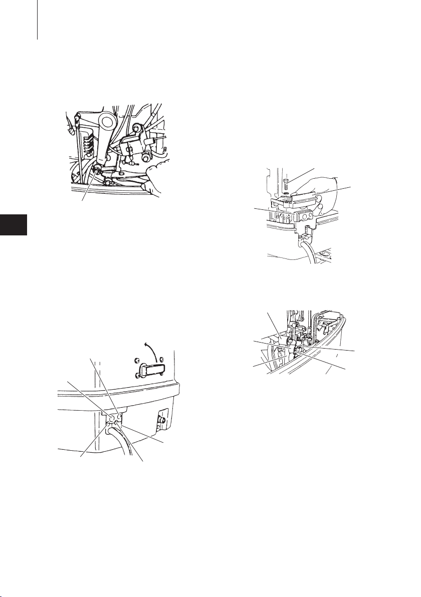
3. Detach the throttle and shit cable joints
by removing the R-pins.
1
1. Cable joint
5
4. Move the remote control lever to the
“FORWARD” “NEUTRAL” and
“REVERSE” positions to confirm that
the shift is working properly, then set
the lever to “NEUTRAL”.
ENOW01706-0
115/140
1. Detach the upper engine cover.
ENOF02319-0
3. Detach the throttle and shit cable joints
by removing the R-pins.
4. Move the remote control lever to the
“FORWARD” “NEUTRAL” and
“REVERSE” positions to confirm that
the shift is working properly, then set
the lever to “NEUTRAL”.
1
2
3
ENOF02322-0
1. Bolt
2. Cord clamp
3. Upper grommet
2
3
4
1. Upper grommet
2. For throttle cable
3. For shft cable
4. For cord assembly B
5. For engine cable herness
2. Detach the upper grommet cord clamp
bolt.
1
1. Shift arm
2. Throttle cable joint
3. Shift cable joint
4. R-pin
5. Washer
5
ENOF02323-0
5. Double-check that the remote control
cables (i.e., the throttle cable and shift
cable) have been connected correctly.
Move the remote control lever forward
to the first point at which it engages
(approx. 32). The cable which moves
first when the lever is turned should be
 Loading...