

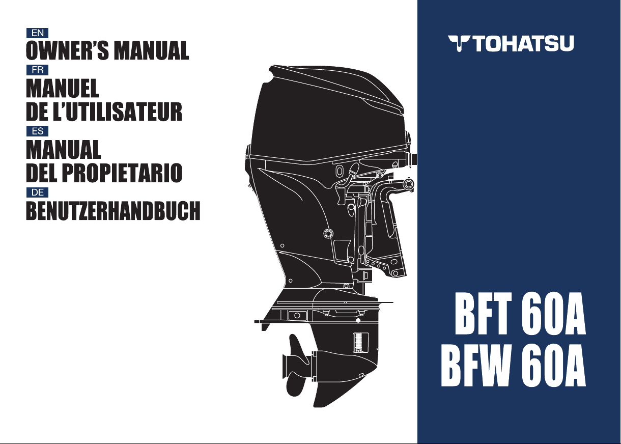
TOHATSU BFT 60A, BFW 60A Owner's Manual
OWNER’S
MANUAL
BFT 60A
BFW 60A
Original instructions

PGM-FI is a trademark of Honda Motor Co , Ltd registered in Japan and other countries
© 2016 Honda Motor Co , Ltd
Thank you for purchasing a
TOHATSU Outboard Motor.
This manual covers operation and
maintenance of the TOHATSU
BFT60A/BFW60A Outboard Motor.
All information in this publication is
based on the latest product
information available at the time of
approval for printing.
Tohatsu Corporation reserves the
right to make changes at any time
without notice and without incurring
any obligation.
No part of this publication may be
reproduced without written
permission.
This manual should be considered a
permanent part of the Outboard
Motor and should remain with it if it
is resold.
Throughout this manual, you will see
safety messages proceeded by the
following words and symbols. Here’s
what they mean:
Indicates serious injury or death
WILL result if instructions are not
followed.
Indicates a strong possibility that
serious personal injury or death
may result if instructions are not
followed.
Indicates a possibility that personal
injury or equipment damage could
result if instructions are not
followed.
Indicates that equipment or
property damage could result if
instructions are not followed.
If a problem should arise, or if you
have any questions about the
Outboard Motor, consult an
authorized TOHATSU Outboard
Motor dealer.
TOHATSU Outboard Motors are
designed to give safe and
dependable service if operated
according to instructions. Read and
understand the Owner’s Manual
before operating the Outboard
Motor. Failure to do so could result
in personal injury or equipment
damage.
• Have your dealer install the tiller
handle.
• The illustration may vary
according to the type.
Gives helpful information.
1
This Owner’s Manual is using the
LEFT STERN BRACKET
FRAME SERIAL NUMBER
ENGINE SERIAL NUMBER
following type names when it
describes the operations special to a
type.
Tiller handle type: H type
Remote control type: R type
The remote control type is classified
into the following three categories
according to the control box position.
• Side-mount type
• Panel-mount type
• To p-mount type
This Owner’s Manual describes with
the side-mount type remote control
box.
Check the type of your outboard
motor and read this Owner’s Manual
thoroughly before operation.
Texts with no type indication are the
information and/or procedures
common to all types.
Record the frame and engine serial
numbers for your reference. Refer to
the serial numbers when ordering
parts, and when making technical or
warranty inquiries.
The frame serial number is stamped
on a plate attached on the left side of
the stern bracket.
Frame serial number:
The engine serial number is stamped
on the upper right side of the engine.
Engine serial number:
2
Control and Feature Identification Codes
TYPE CODE Example
LRTD
Destination
U: Europe, D: General Export
Tilt system
T: Power Trim/Tilt (with hydraulic assisted function)
Control System
H: Tiller Handle Control
R: Remote Control
Shaft Length
BFT60A: L= 521 mm (20.5 in) (Long Shaft)
BFW60A: L= 531 mm (20.9 in) (Long Shaft)
Model BFT60A BFW60A
Type LRTD LRTU LHTD LRTU
Shaft Length
Tiller Handle
Remote Control
Power Trim/Tilt
Trim Meter
Tachometer
Rudder Meter
Tilt Limit Mechanism
Portable Fuel Tank (25 L)
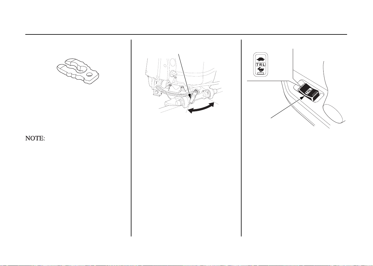
TRL (Trolling) Control Switch
50 Ste e ring An gle R od
Note that the types of the outboard motor differ according to the countries where they are sold.
BFT60A/BFW60A is provided with the following
types according to the shaft length, control system,
and tilt system.
: Optional Equipment
*
**
****
*
**
****
**
**
****
**
**
–
–
–
–
*
*
*
*
*
3

CONTENTS
1. SAFETY ........................................................................................... 7
SAFETY INFORMATION ........................................................... 7
2. SAFETY LABEL LOCATIONS.................................................... 10
CE mark location......................................................................... 12
3. COMPONENT IDENTIFICATION .............................................. 13
4. CONTROLS AND FEATURES (H type)...................................... 21
H type
Engine Switch (Ignition Switch)............................................ 21
Shift Lever.............................................................................. 22
Throttle Grip........................................................................... 23
Throttle Friction Adjuster ...................................................... 23
Emergency Stop Switch......................................................... 24
Emergency Stop Switch Lanyard/Clip................................... 24
Steering Friction Adjuster................. ..................................... 25
TRL (Trolling) Control Switch .............................................. 25
R type
SIDE-MOUNT TYPE................................................................. 26
Remote Control Lever......................................... ................... 26
Neutral Release Lever................ ............................................ 27
Engine Switch (Ignition Switch)............................................ 27
Fast Idle Lever................................................................ ........ 28
Emergency Stop Switch......................................................... 28
Emergency Stop Switch Lanyard/Clip................................... 29
Spare Emergency Stop Switch Clip (optional equipment) .... 30
TRL (Trolling) Control Switch .............................................. 30
Common
Power Trim/Tilt Switch.......................................................... 31
NMEA Interface Coupler .... ................................................... 32
Operating Hour Notification System ......... ............................ 32
Trim Meter ............................................................................. 35
Power Tilt Switch (outboard motor pan)............................... 35
Manual Relief Valve ............................................. ................. 36
Tilt Lock Lever...................................................................... 36
Oil Pressure Indicator/Buzzer................................................ 37
Overheat Indicator/Buzzer..................................................... 38
ACG Indicator/Buzzer........................................................... 39
PGM-FI Indicator/Buzzer...................................................... 40
Trim Tab................................................................................ 41
Anode..................................................................................... 42
Cooling Water Check Hole.................................................... 43
Cooling Water Intake Port..................................................... 43
Engine Cover Fixing Lever ................................................... 44
Fuel Filler Cap (equipped type)................................ ............. 44
Fuel Gauge.. ........................................................................... 45
Fuel Line Connector And Joint ............................................. 45
Tachometer ............................................................................ 45
Rudder Meter......................................................................... 46
5. INSTALLATION........................................................................... 47
Transom Height .......................................................................... 47
Location...................................................................................... 48
Installation Height ............. .. ....................................................... 48
Outboard Motor Installation ....................................................... 49
Outboard Motor Angle Inspection (Cruising) ............................ 50
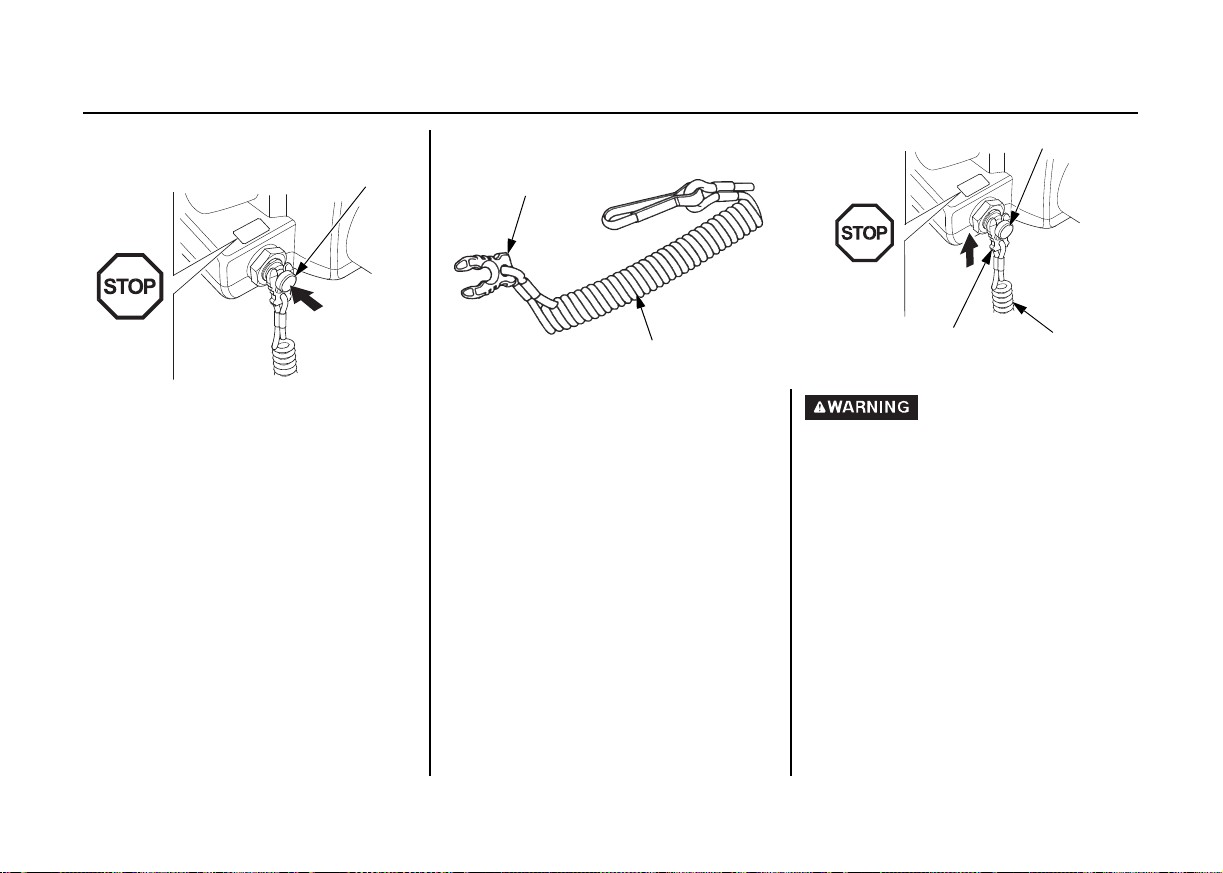
Battery Connections.................................................................... 51
Remote Control Installation. ............................................... ........ 53
<Remote Control Box Location> .......................................... 53
<Remote Control Cable Length> .......................................... 54
Propeller Selection...................................................................... 54
4

CONTENTS
6. PRE-OPERATION CHECKS ........................................................ 55
Engine Cover Removal/Installation ............................................ 55
Engine Oil ................................................................................... 56
Fuel........ ............................................... ....................................... 58
GASOLINE CONTAINING ALCOHOL.............................. 59
Propeller and Cotter Pin Inspection .................. .. ........................ 60
Tiller Handle Height/Angle Adjustment (H type) ...................... 61
Steering Handle Friction (H type)................................ ............... 62
Remote Control Lever Friction (Side-mount type) ..................... 62
Fuel Filter/Water Separator......................................................... 62
Battery......................................................................................... 63
Other Checks............................ ............................................... .... 64
7. STARTING THE ENGINE............................................................ 65
Fuel Line Connection.................................................................. 65
Fuel Priming................................................................................ 66
Starting the Engine (H type) ........... ............................................ 67
Starting the Engine (R type)... ............................................... ...... 71
Emergency Starting..................................................................... 74
8. OPERATION.................................................................................. 80
Break-in Procedure................. ............................................... ...... 80
H type
Gear Shifting............ .............................................................. 81
Steering .................. ................................................................ 82
Cruising.................................................................................. 83
R type
Gear Shifting............ .............................................................. 85
Cruising.................................................................................. 86
Common
TRL (Trolling Control) Switch.............................................. 88
Trimming the Outboard Motor.............................................. 89
Trim Meter............................................................................. 91
Tilting the Outboard Motor ................................................... 92
Moorage........................................ ......................................... 93
Manual Relief Valve ............................................. ................. 94
Power Tilt Switch (outboard motor pan)............................... 94
Trim Tab Adjustment ................... ......................................... 95
Engine Protection System...................................................... 97
<Engine Oil Pressure, Overheat, PGM-FI and
ACG Warning Systems> ................................................97
<Over-rev Limiter> .......................................................... 101
<Anode> .......................................................................... 101
Shallow Water Operation ............. .. ..................................... 102
Multiple Outboard Motors................................................... 102
9. STOPPING THE ENGINE.......................................................... 103
Emergency Engine Stop ......................................................... .. 103
Normal Engine Stop ................................................................. 104
(H type)........................................... ..................................... 104
(R type)................................................................................ 105
10. TRANSPORTING ..................................................................... 106
Fuel Line Disconnection........................................................... 106
Transporting.......... .................................................................... 107
Trailering ....................... .. ......................................................... 109
11. CLEANING AND FLUSHING................................................. 110
5

CONTENTS
12. MAINTENANCE....................................................................... 111
Tool Kit, Spare and Emergency Parts............. .......................... 112
MAINTENANCE SCHEDULE................... ............................. 113
Engine Oil ................................................................................. 115
Spark Plugs................................................................................ 116
Battery....................................................................................... 118
Lubrication ................................................................................ 121
Fuel Filter/Water Separator....................................................... 123
Fuel Tank and Tank Filter......................................................... 126
EMISSION CONTROL SYSTEM ........................................... 127
Fuse ............................................... ............................................ 128
Propeller......... ........................................................................... 130
Submerged Outboard Motor ..................................................... 132
13. STORAGE.................................................................................. 134
Fuel........ ............................................... ..................................... 134
Vapor Separator Draining ......................................................... 135
Engine Oil ................................................................................. 136
Battery Storage.......................................................................... 137
Outboard Motor Position........................................................... 138
14. DISPOSAL ................................................................................. 139
15. TROUBLESHOOTING ............................................................. 140
16. SPECIFICATIONS..................................................................... 141
17. ‘‘EC DECLARATION OF CONFORMITY’’
CONTENT OUTLINE............................................................... 144
18. INDEX........................................................................................ 149
6
SAFETY INFORMATION
• TOHATSU outboard motor is
designed to give safe and
dependable service if operated
according to instructions.
Read and understand the
Owner’s Manual before
operating the outboard motor.
Failure to do so could result in
personal injury or equipment
damage.
• Gasoline is harmful or fatal if
swallowed. Keep the fuel tank
out of reach of children.
• Gasoline is extremely
flammable and is explosive
under certain conditions.
Refuel in a well-ventilated area
with the engine stopped.
• Do not smoke or allow flames or
sparks where the engine is
refueled or where gasoline is
stored.
• Do not overfill the fuel tank.
After refueling make sure that
the fuel filler cap is closed
properly and securely.
• Be careful not to spill any fuel
while refueling. Spilled fuel or
fuel vapor may ignite. If any
fuel is spilled make sure that the
area is dry before starting the
engine.
For your safety and the safety of
others, pay special attention to these
precautions.
Operator Responsibility
1. SAFETY
7
SAFETY
Shift to the neutral position and
then shift to the reverse position
at low engine speed.
Do not shift to the reverse position
suddenly at high engine speed.
Moving parts can injure you.
Install the engine cover after
emergency starting the engine. Do
not operate the outboard motor
without the engine cover.
• Know how to stop the engine
quickly in case of emergency.
Understand the use of all controls.
• Do not exceed the boat
manufacturer’s power
recommendation, and be sure that
the outboard motor is properly
mounted.
• Never permit anyone to operate the
outboard motor without proper
instruction.
• Stop the engine immediately if
anyone falls overboard.
• Do not run the engine while the
boat is near anyone in the water.
• Attach the emergency stop switch
lanyard securely to the operator.
• Before operating the outboard
motor, familiarize yourself with all
laws and regulations relating to
boating and the use of outboard
motors.
• Do not attempt to modify the
outboard motor.
• Always wear a life-jacket when on
board.
• Do not operate the outboard motor
without the engine cover. Exposed
moving parts can cause injury.
• Do not remove any guards, labels,
shields, covers or safety devices;
they are installed for your safety.
8

SAFETY
Fire and Burn Hazards
Gasoline is extremely flammable, and
gasoline vapor can explode. Use
extreme care when handling gasoline.
KEEP OUT OF REACH OF
CHILDREN.
• Remove the fuel tank from the boat
for refueling.
• Refuel in a well-ventilated area
with the engine stopped. Keep
flames and sparks away, and do not
smoke in the area.
• Refuel carefully to avoid spilling
fuel. A void overfilling the fuel tank
(there should be no fuel in the filler
neck). After refueling, tighten the
fuel filler cap securely. If any fuel
is spilled, make sure the area is dry
before starting the engine.
The engine and exhaust system
become very hot during operation and
remain hot for a while after stopping.
Contact with hot engine components
can cause burns and may ignite some
materials.
• Avo id touching a hot engine or
exhaust system.
• Allow the engine to cool before
performing maintenance or
transporting.
Carbon Monoxide Poisoning
Hazard
Exhaust contains poisonous carbon
monoxide, a colorless and odorless
gas. Breathing exhaust can cause loss
of consciousness and may lead to
death.
• If you run the engine in an area that
is confined, or even partially
enclosed, the air can become
contaminated with a dangerous
amount of exhaust gas. To keep
exhaust gas from building up,
provide adequate ventilation.
9
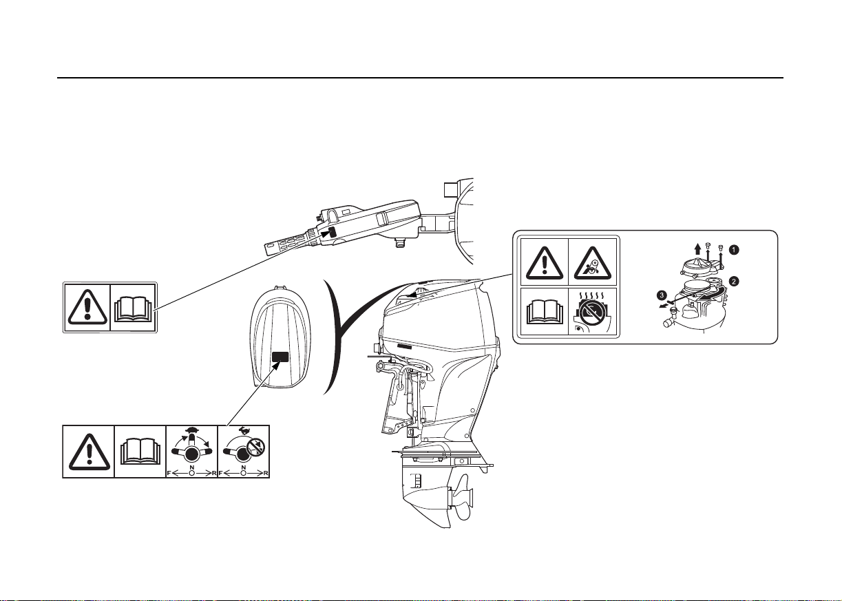
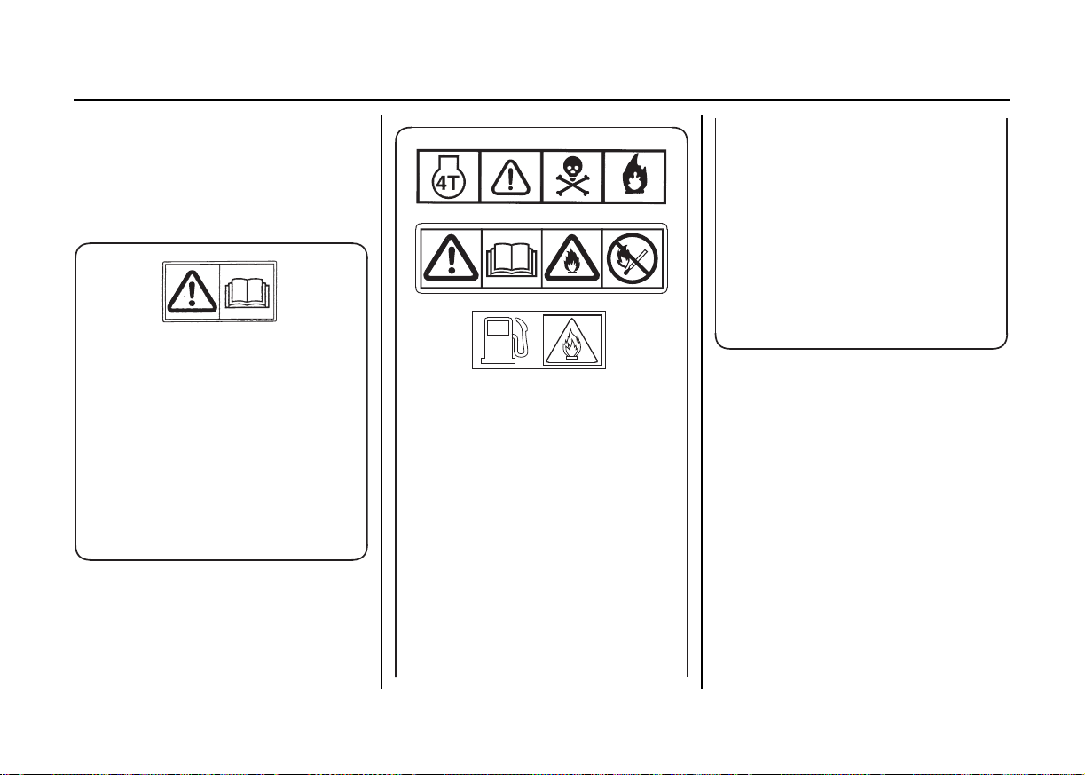
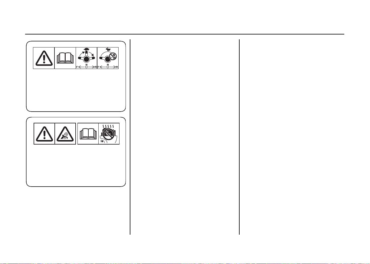
2. SAFETY LABEL LOCATIONS
READ OWNER’S
MANUAL
READ OWNER’S MANUAL
GEAR SHIFTING
READ OWNER’S MANUAL
EMERGENCY ENGINE STARTING
[Equipped type]
These labels are in the locations shown.
They warn you of potential hazards that can cause serious injury.
Read the labels and safety notes and precautions described in this manual carefully.
If a label comes off or becomes hard to read, contact your TOHATSU outboard motor dealer for a replacement.
10
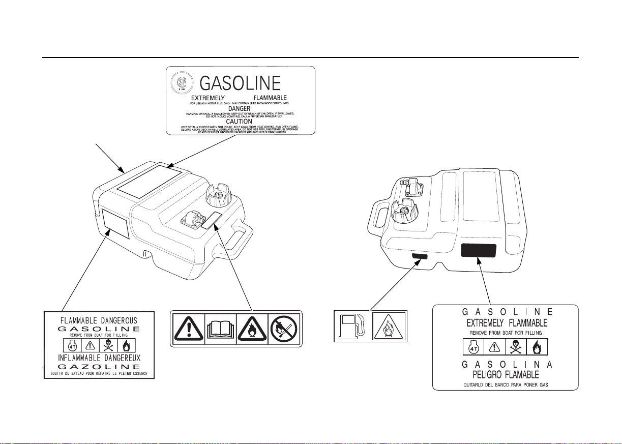
PORTABLE FUEL TANK
FUEL CAUTION
FUEL CAUTION
SAFETY LABEL LOCATIONS
11
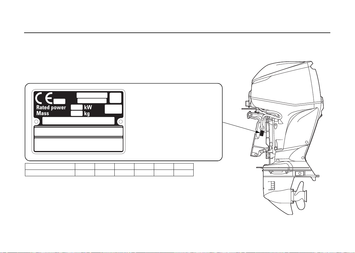
CE MARK
Name and address of manufacturer and authorized representative are written in the
“EC Declaration of Conformity” CONTENT OUTLINE in this Owner’s Manual.
Year code D E F G H J
Year of manufacture 2013 2014 2015 2016 2017 2018
(1) Model name
(2) Engine family name
(3) Year code
(4) Rated power
(5) Dry mass (weight) (with propeller,
without battery cable)
(6) Country of manufacture
(7) Frame number
(8) Manufacturer and address
(9) Name and address of authorized
representative
(10)The identification number of the
notified body
(1)
(2)
(3)
(4)
(5)
(6)
(7)
(8)
(9)
(10)
SAFETY LABEL LOCATIONS
CE mark location
[U type only]
12
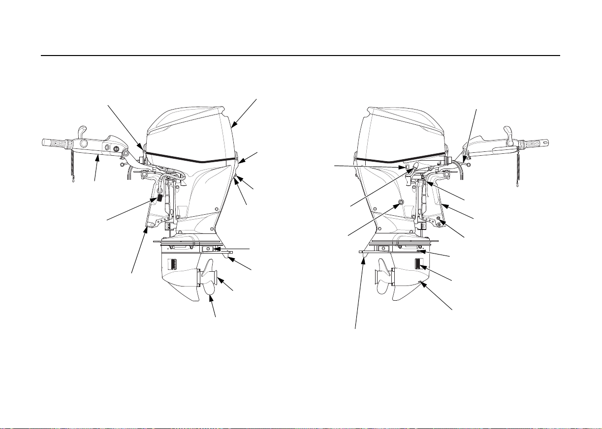
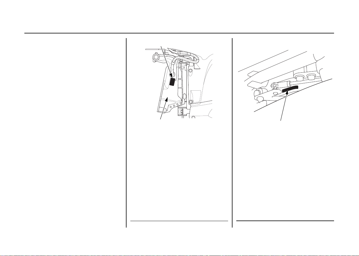
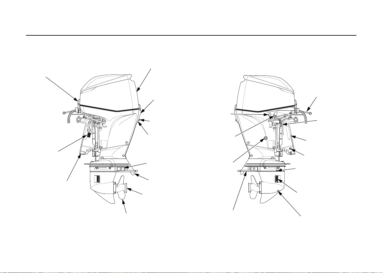
[H (Tiller Handle) type]
ENGINE COVER
FIXING LEVER
(front)
TILLER
HANDLE
FRAME SERIAL
NUMBER
ANODE
PROPELLER
(equipped type or optional
equipment)
EXHAUST PORT/WATER
OUTLET PORT
TRIM TAB
ANODE
(each side)
COOLING
WATER
CHECK
HOLE
IDLE PORT
ENGINE COVER
FIXING LEVER
(rear)
ENGINE COVER
POWER TILT
SWITCH
FLUSH PORT
CONNECTOR
ENGINE OIL
DRAIN BOLT
ANTICAVITATION PLATE
GEAR OIL DRAIN PLUG SCREW
COOLING W ATER
INTAKE PORT
(each side)
GEAR OIL LEVEL
PLUG SCREW
MANUAL RELIEF VALVE
STERN
BRACKET
TILT LOCK LEVER
FUEL HOSE
3. COMPONENT IDENTIFICATION
13
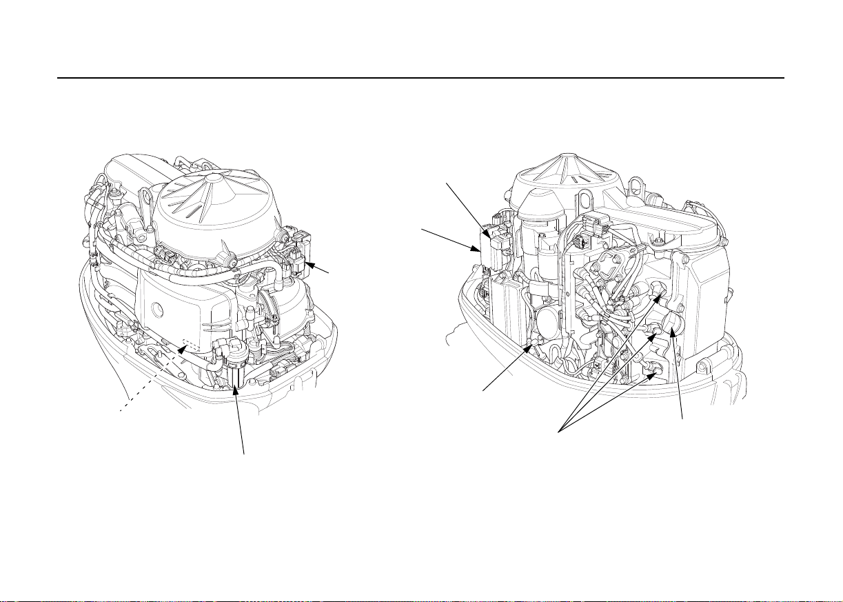
COMPONENT IDENTIFICATION
ENGINE SERIAL
NUMBER
FUEL FILTER/WATER SEPARATOR
(inside strainer cup)
INTERFACE
COUPLER
MAIN FUSE BOX
ACG FUSE
OIL LEVEL DIPSTICK
SPARK PLUG CAPS
ENGINE OIL FILLER CAP
14

TILLER HANDLE
INDICATORS
(Oil pressure, Overheat, ACG, PGM-FI)
ENGINE SWITCH
ENGINE SWITCH KEY
STEERING FRICTION
ADJUSTER
FUEL HOSE
EMERGENCY STOP
SWITCH CLIP
EMERGENCY STOP SWITCH
LANYARD
EMERGENCY
STOP SWITCH
POWER TRIM/TILT SWITCH
SPARE EMERGENCY STOP SWITCH CLIP
Store the spare emergency stop switch
clip in the tool bag.
TRL (Trolling Control)
SWITCH
SHIFT LEVER
THROTTLE FRICTION
ADJUSTER
THROTTLE GRIP
COMPONENT IDENTIFICATION
15
COMPONENT IDENTIFICATION
ENGINE COVER
FIXING LEVER
(front)
FRAME SERIAL
NUMBER
ANODE
PROPELLER
(equipped type or optional equipment)
EXHAUST PORT/WATER
OUTLET PORT
TRIM TAB
ANODE
(each side)
COOLING
WATER
CHECK
HOLE
IDLE PORT
ENGINE COVER
FIXING LEVER
(rear)
ENGINE COVER
POWER TILT
SWITCH
FLUSH PORT
CONNECTOR
ENGINE OIL
DRAIN BOLT
ANTICAVITATION PLATE
GEAR OIL DRAIN
PLUG SCREW
COOLING W A TER
INTAKE PORT
(each side)
GEAR OIL LEVEL
PLUG SCREW
MANUAL RELIEF
VALVE
STERN
BRACKET
TIL T LOCK
LEVER
FUEL HOSE
[R (Remote Control) type]
16
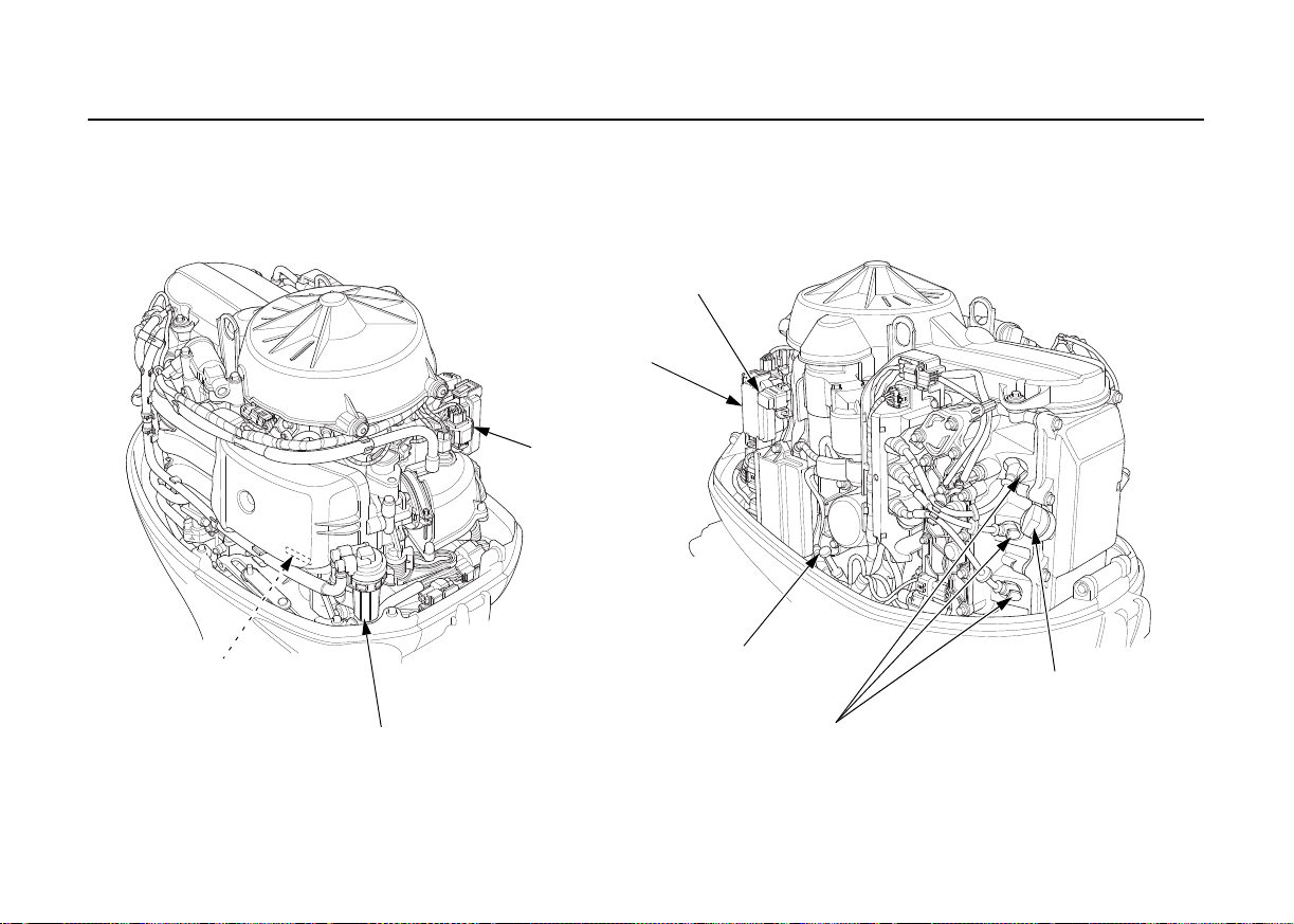
ENGINE SERIAL
NUMBER
FUEL FILTER/WATER SEPARATOR
(inside strainer cup)
INTERFACE
COUPLER
ACG FUSE
MAIN FUSE BOX
OIL LEVEL DIPSTICK
SPARK PLUG CAPS
ENGINE OIL FILLER CAP
COMPONENT IDENTIFICATION
17
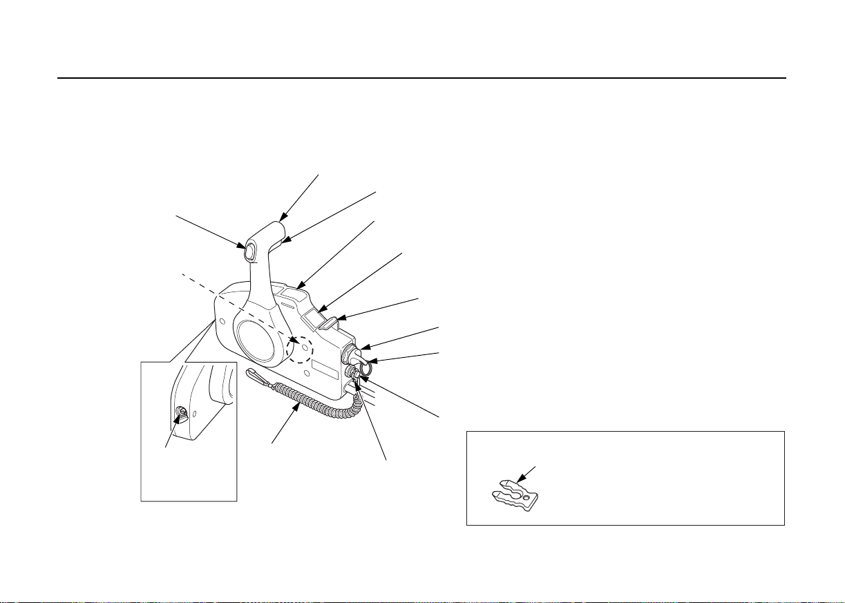
COMPONENT IDENTIFICATION
REMOTE CONTROL LEVER
POWER TRIM/TILT SWITCH
CONTROL
LEVER
FRICTION
ADJUSTER
EMERGENCY STOP
SWITCH LANYARD
EMERGENCY
STOP
SWITCH
CLIP
EMERGENCY STOP SWITCH
ENGINE SWITCH KEY
ENGINE SWITCH
BUZZER
(inside)
F A ST IDLE LEVER
INDICATORS
(Oil pressure, Overheat,
ACG, PGM-FI)
NEUTRAL RELEASE LEVER
TRL (Trolling) CONTROL SWITCH
SPARE EMERGENCY ST OP SWITCH CLIP
Store the spare emergency stop switch
clip in the tool bag.
REMOTE CONTROL BOX (R type)
(equipped type or optional equipment)
SIDE-MOUNT TYPE
18
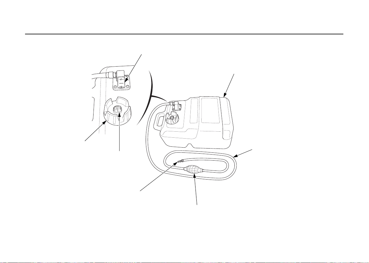
[Common]
FUEL GAUGE
FUEL FILLER CAP
FUEL FILLER CAP
VENT KNOB
FUEL LINE JOINT
(outboard motor side)
PRIMING BULB
FUEL TANK TUBE
ASSEMBLY
PORTABLE FUEL TANK
(equipped type or optional equipment)
COMPONENT IDENTIFICATION
19
COMPONENT IDENTIFICATION
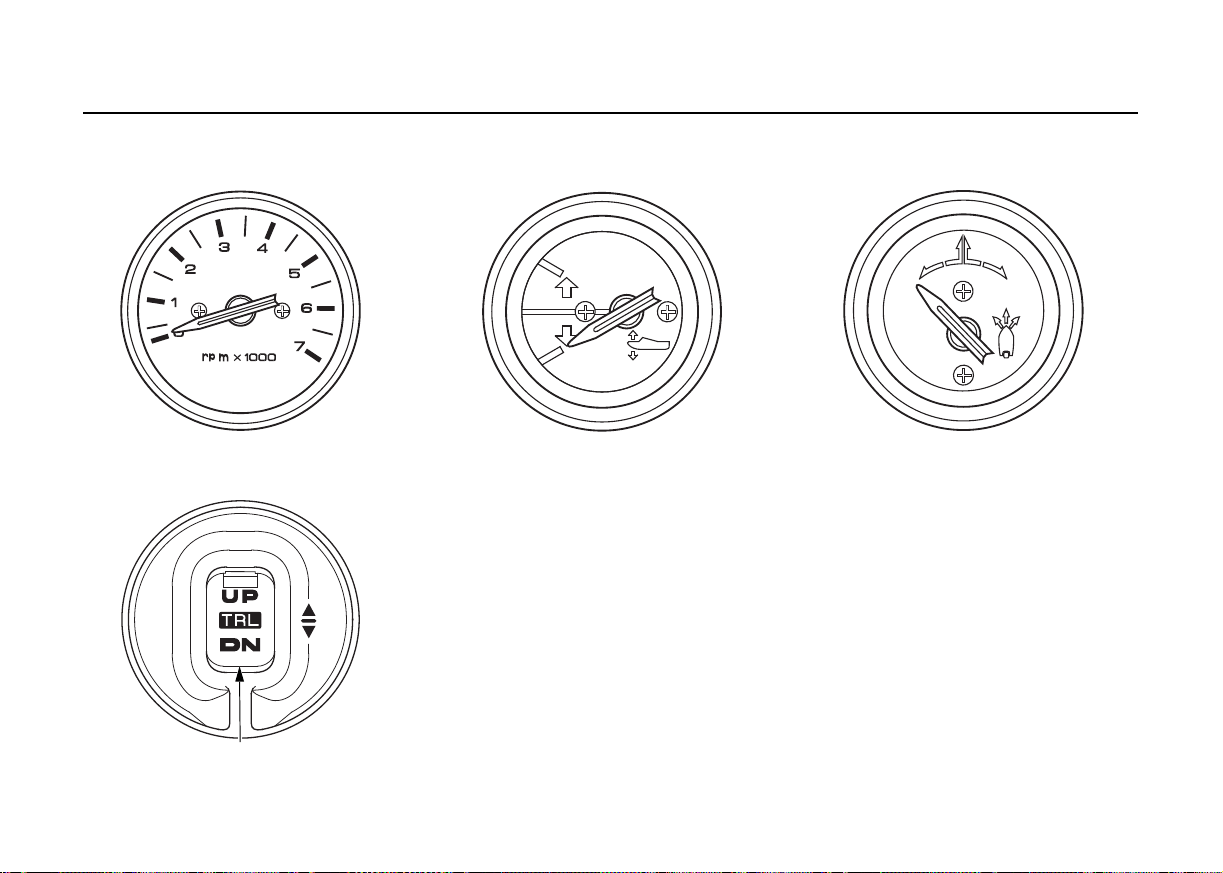
TRL (Trolling Control) SWITCH
TACHOMETER
(equipped type or optional equipment)
TRIM METER
(equipped type or optional equipment)
RUDDER METER
(optional equipment: R type)
TRL (Trolling Control) SWITCH PANEL
(optional equipment: R type)
20
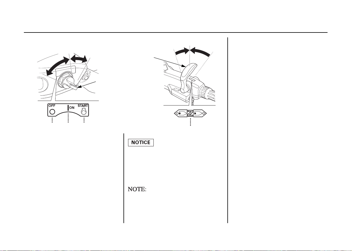
ON
START
OFF
ENGINE SWITCH (IGNITION SWITCH)
OFF ON START
SHIFT LEVER
NEUTRAL
NEUTRAL
Engine Switch (Ignition Switch)
This tiller handle is equipped with an
automotive type engine switch.
Key positions:
START: to start the engine.
ON: to run the engine after
starting.
OFF: to stop the engine
(IGNITION OFF).
Do not leave the engine switch
(ignition switch) ON (key in ON
position) when the engine is not
running as the battery will
discharge.
The starter motor will not work
unless the shift lever is in the
NEUTRAL position.
4. CONTROLS AND FEATURES (H type)
21
CONTROLS AND FEATURES (H type)
Shift Lever
NEUTRAL
REVERSE
FORWARD
SHIFT
LEVER
FORWARDREVERSE
NEUTRAL
SLOW
THROTTLE GRIP
SLOW
SHIFT LEVER
Use the shift lever to run the boat in
forward or reverse gear, or to cut off
the engine power from the propeller.
There are three positions for the shift
lever.
FORWARD:
NEUTRAL:
REVERSE:
22
The boat moves ahead.
The engine power is cut
off from the propeller.
The boat does not
move.
The boat reverses.
The shift lever will not move unless
the throttle grip is in the fully closed
position.
You can chose which side to have the
shift lever installed. Consult your
authorized TOHATSU outboard
motor dealer.
CONTROLS AND FEATURES (H type)
THROTTLE GRIP
THROTTLE
INDICATOR
FAST START
SLOW
THROTTLE FRICTION ADJUSTER
RELEASE
THROTTLE GRIP
FIX
Throttle Grip
Turn the grip clockwise or
counterclockwise to adjust the engine
speed. Turning the grip in the
direction shown by arrow increases
the engine speed.
The curve on the grip indicates the
engine speed.
Throttle Friction Adjuster
The throttle friction adjuster adjusts
resistance to throttle grip rotation.
Turn the adjuster clockwise to
increase friction for holding a throttle
setting while cruising.
Turn the adjuster counterclockwise to
decrease friction for easy throttle grip
rotation.
23
CONTROLS AND FEATURES (H type)
EMERGENCY STOP SWITCH
STOP
Emergency Stop Switch Lanyard/Clip
EMERGENCY STOP
SWITCH CLIP
EMERGENCY STOP
SWITCH LANYARD
STOP
EMERGENCY STOP
SWITCH CLIP
EMERGENCY
STOP SWITCH
LANYARD
EMERGENCY STOP SWITCH
Emergency Stop Switch
Press the emergency stop switch to
stop the engine.
24
The emergency stop switch lanyard is
provided to stop the engine
immediately when the operator falls
overboard or away from the outboard
motor.
The engine stops when the clip at the
end of the emergency stop switch
lanyard is pulled out of the
emergency stop switch.
When operating the outboard motor,
be sure to attach one end of the
emergency stop switch lanyard
securely to the operator.
If the emergency stop switch
lanyard is not set, the boat might
run out of control when the
operator, for example, falls
overboard and is not able to
operate the outboard motor.
For the sake of the operator’s and the
passengers’ safety, be sure to set the
emergency stop switch clip located at
one end of the emergency stop switch
lanyard with the emergency stop
switch. Attach the other end of the
emergency stop switch lanyard
securely to the operator.
CONTROLS AND FEATURES (H type)
SPARE EMERGENCY STOP
SWITCH CLIP
STEERING FRICTION ADJUSTER
To increase
friction
(LOCK)
To decrease
friction
(FREE)
TROLLING
CONTROL SWITCH
DOWN
UP
The engine does not start unless the
emergency stop switch clip is set on
the emergency stop switch.
Store the spare emergency stop
switch clip in the tool bag. Use the
spare emergency stop switch clip to
make the disabled engine start when
the emergency stop switch lanyard is
not available as, for example, when
the operator falls overboard.
Steering Friction Adjuster
The steering friction adjuster adjusts
steering resistance.
Less friction allows the outboard
motor to turn more easily. More
friction helps to hold a steady course
while cruising or to prevent the
outboard motor from swinging while
trailering the boat.
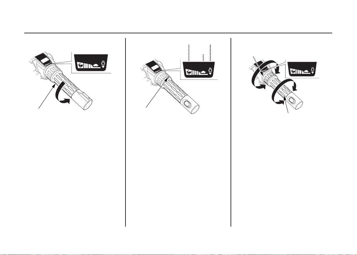
TRL (Trolling) Control Switch
The engine speed can be adjusted
with the trolling control switch when
in trolling mode.
If you press and hold the TRL control
switch while cruising with the throttle
closed, the mode changes to trolling
mode.
25
CONTROLS AND FEATURES (R type)
SIDE-MOUNT TYPE
Remote Control Lever
REMOTE CONTROL LEVER
NEUTRAL RELEASE LEVER
FORWARD
NEUTRAL
REVERSE
REMOTE CONTROL LEVER
MAXIMUM
THROTTLE OPENING
MINIMUM
FORWARD
SHIFT
32° 32°
SHIFT
NEUTRAL
MINIMUM
REVERSE
THROTTLE OPENING
MAXIMUM
Shifting gear into forward, reverse, or
neutral and the engine speed
adjustment can be performed with the
remote control lever.
It is necessary to pull up the neutral
release lever to operate the remote
control lever.
26
FORWARD:
Moving the lever to the FORWARD
position (i.e. approximately 32° from
the NEUTRAL position) engages the
gear into forward. Moving the lever
further from the FORWARD position
will increase the throttle opening and
the boat forward speed.
NEUTRAL:
Engine power is cut off from the
propeller.
REVERSE:
Moving the lever to the REVERSE
position (i.e. approximately 32° from
the NEUTRAL position) engages the
gear into reverse. Moving the lever
further from the REVERSE position
will increase the throttle opening and
the boat reverse speed.
CONTROLS AND FEATURES (R type)
REMOTE CONTROL LEVER
NEUTRAL RELEASE LEVER
ENGINE
SWITCH
START
ON
OFF
Neutral Release Lever
The neutral release lever is set on the
remote control lever to prevent an
accidental operation of the remote
control lever.
The remote control lever does not
operate unless it is moved while
pulling the neutral release lever up.
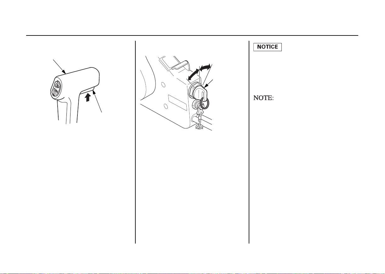
Engine Switch (Ignition Switch)
Do not leave the engine switch
(ignition switch) ON (key in ON
position) when the engine is not
running as the battery will
discharge.
The starter motor will not work
unless the remote control lever is in
the NEUTRAL position, and the clip
is in the emergency stop switch.
This remote control is equipped with
an automotive type engine switch.
On the side-mount type, the engine
switch locates on your side near the
remote control box.
Key positions:
START: to start the engine.
ON: to run the engine after
starting.
OFF: to stop the engine
(IGNITION OFF).
27
 Loading...