

TOHATSU BFT 115A, BFT 150A Owner's Manual
EN
OWNER’S MANUAL
FR
MANUEL
DE L’UTILISATEUR
ES
MANUAL
DEL PROPIETARIO
DE
BENUTZERHANDBUCH
BFT 115A
150A
OWNER’S
MANUAL
BFT 115A
150A
Original instructions

PGM-FI is a trademark of Honda Motor Co , Ltd registered in Japan and other countries
© 2013 Honda Motor Co , Ltd
Thank you for purchasing a
TOHATSU Outboard Motor.
This manual covers operation and
maintenance of the TO
BFT115A/150A Outboard Motor.
All
information in this publication is
based on the latest
information available at the
approval for
ohatsu Corporation reserves the
T
right to make change
without notice and without incurring
any obligation.
No part of this publication may be
reproduced without writ
permission.
This manual should be considered a
permanent
Motor and should remain with it if it
is resold.
printing.
part of the Outboard
HATSU
product
time of
s at any time
ten
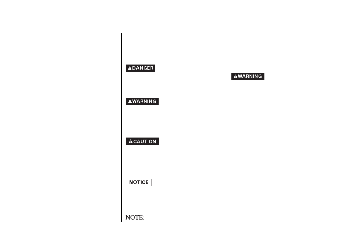
Throughout this manual, you will see
t
y messages proceeded by the
safe
following words and symbols. Here’s
what they mean:
Indicates serious injury or death
WILL result if instructions are not
followed.
Indicates a strong possibility that
serious personal injury or death
may result if instructions are not
followed.
Indicates a possibility that personal
injury or equipment damage could
result if instructions are not
followed.
Indicates that equipment or
property damage could result if
instructions are not followed.
If a problem should arise, or if you
ha
ve any questions about the
Outboard Motor, consult an
authorized TOHATSU Outboard
Motor dealer.
TOHATSU Outboard Motors are
designed to give safe and
dependable service if operated
according to instructions. Read and
understand the Owner’s Manual
before operating the Outboard
Motor. Failure to do so could result
in personal injury or equipment
damage.
Gives helpful information.
1
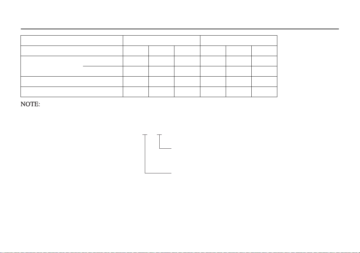
Model BFT115A BFT150A
TYPE CODE
Example
X
D
Destination
D: General Export, U: Europe
Transom Height
L: 508 mm (20.0 in), X: 635 mm (25.0 in)
Type LD LU XU XD LU XU
Transom Height 508 mm (20.0 in)
(Shaft Length) 635 mm (25.0 in)
Standard Rotating Propeller Shaft
Power Trim/Tilt
Note that the types of the outboard motor differ according to the countries where they are sold.
BFT115A/150A is provided with the
following types according to the shaft length and
the rotating direction of the propeller shaft.
2
The remote control type is classified
FRAME SERIAL NUMBER
ENGINE SERIAL NUMBER
into the following three categories
according to the control box position.
Side-mount type: R1 type
Panel-mount type: R2 type
Top-mount type: R3 type
Check the type of your outboard
motor and read this
Owner’s Manual
thoroughly before operation. Texts
with no type indication are the
information and/or procedures
common to all types.
Record the frame and engine serial
numbers for your reference.
Refer to
the serial numbers when ordering
parts, and when making technical or
warranty inquiries.
The frame serial number is stamped
on a plat
e attached on the right side of
the stern bracket.
Frame serial number:
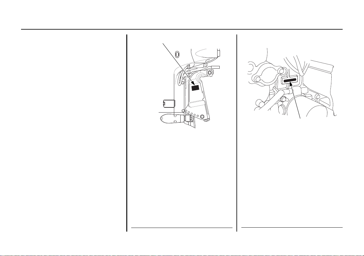
The engine serial number is stamped
on the upper right side of the engine.
Engine serial number:
3

CONTENTS
1. SAFETY ...........................................................................................6
SAFETY INFORMATION . ............................. .............................6
2. SAFETY LABEL LOCATIONS ......................................................8
3. COMPONENT IDENTIFICATION ..............................................10
4. CONTROLS AND FEATURES ....................................................14
Remote Control Lever ................................................. ................14
R1 type ...................................................................................14
R2 type ...................................................................................15
R3 type ...................................................................................16
Neutral Release Lever ............................. ............................. .......17
Engine Switch .............................................................................17
Fast Idle Lever/Fast Idle Button ................................ ..................18
PGM-FI Indicator/Buzzer ...........................................................19
ACG Indicator/Buzzer .............................................. ..................19
Oil Pressure Indicator/Buzzer .....................................................20
Overheat Indicator/Buzzer .. ............................. ...........................20
Water Separator Buzzer ............................ ............................. .....20
Power Trim/Tilt Switch ...............................................................21
Trim Meter (optional equipment) ................................................22
Power Tilt Switch (outboard motor pan) ....................................22
TRL (Trolling) Control Switch Panel
(optional equipment) ...............................................................23
Manual Relief Valve ...................................................................23
Emergency Stop Switch .................................................. ............24
Emergency Stop Switch Lanyard/Clip ........................................24
Spare Emergency Stop Switch Clip ................. ...........................25
Tilt Lock Lever ...........................................................................26
Trim Tab ......................................................................................26
Anode ..........................................................................................
Cool
ing Water Check Hole .........................................................27
Cooling Water Intake Port ...................... .. ............................. .....27
Engine Cover Latch .....................................................................27
26
4
Tachometer (optional equipment) ............................................... 28
NMEA Interface Coupler ........................................................... 28
5. IN
STALLATION ........................................................................... 29
Transom Height .......................................................................... 29
Location ..................... ................................................... .............. 30
Installation Height .................................................. .................... 30
Outboard Motor Installation ....................................................... 31
Outboard Motor Angle Inspection (Cruising) ............................ 32
Battery Connections ........................................... ......................... 33
Remote Control Installation (optional equi
Remote Control Box Location .. ............................. ................ 36
Remote Control Cable Length ....... ............................. ........... 36
Propeller Selection ..................... .. ............................................... 37
Fuel Line Connection .................................................................
RE-OPERATION CHECKS ........................................................ 38
6. P
Engine Cover Removal/Installation ............................................ 38
Engine Oil ................................................................................... 39
Fuel ............................................................................................. 41
GASOLINE CONTAINING ALCOHOL ............................. 42
Propeller and Cotter Pin Inspection ............. .. ............................. 43
Remote Control Lever Friction ................................. .................. 44
Water Separator ............................................. ............................. 44
Battery ........................ ..... .. .... ..... .. ..... .... .. ..... .... .. ..... .... .. ..... .... ... .. 45
Other Checks ........................ ... ............................. ...................... 46
7. STARTING THE ENGINE ........................................................... 47
Fuel Priming ............................................................................... 47
Starting the Engine ..................................................................... 47
R1 type ................................................................................... 47
R2, R3 types ........................................................ .................. 51
pment) ..................... 35
37

CONTENTS
8. OPERATION ..................................................................................55
Break-in Procedure .................. ............................. .......................55
Gear Shifting ..................... ............................. .............................56
R1 type ...................................................................................56
R2 type ...................................................................................57
R3 type ...................................................................................58
Cruising ........................... ................................................ ............59
TRL (Trolling) Control Switch (optional equipment) .... ............61
Trimming the Outboard Motor ............ ............................ ............62
Trim Meter (optional equipment) ................................................64
Tilting the Outboard Motor .........................................................65
Moorage ......................................................................................66
Power Tilt Switch (outboard motor pan) ....................................67
Manual Relief Valve ...................................................................68
Trim Tab Adjustment ..................................................................69
Engine Protection System ...........................................................70
Engine Oil Pressure, Overheat
PGM-FI and ACG Warning Systems .................................70
Over-rev Limiter ....................................................................74
Anodes ....................................................................................
Shallow Water Operation ................................... .........................74
Multiple Outboard Motors .......................... ............................. ...75
9. STOPPING THE ENGINE .............................................................76
Emergency Engine Stop ..................................... .........................76
Normal Engine Stop ....................................................................76
10. TRANSPORTING ........................................................................78
Fuel Line Disconnection .............................................................78
Transporting ................................................................................ 78
Trailering ...................... ........................... ............................. ....... 79
11. CLEANING AND FLUSHING ...................................................80
12. MAINTENANCE .........................................................................81
Tool Kit and Owner’s Manual ....................................................82
ter Contamination,
, Wa
74
Spare Emergency Stop Switch Clip (optional equipment) .... 82
Maintenance Schedule ................................................................ 83
Engine Oil ................................................................................... 85
Spark Plugs ................................................................................. 87
Lubrication .................... ............. ............. .............. ............. ......... 92
Fuel Filter .................................................................................... 94
Water Separator ............................................. ............................. 97
EMISSION CONTROL SYSTEM ............................................. 99
Battery ........................ ..... .. .... ..... .. ..... .... .. ..... .... .. ..... .... .. ..... .... ... 100
Fuse .......................... ...................... ......................... .................. 102
Main Fuse ............. ............................. ............................. ..... 103
ACG Fuse ................ ............................ ............................. ... 103
Propeller ........................ ............. ............. .............. ............. ....... 104
Submerged Outboard Motor .... ............................. .................... 105
13. STORAGE ................................................................................. 107
Fuel ........................................................................................... 107
Vapor Separator Draining ......................................................... 107
Engine Oil ................................................................................. 108
Battery Storage .............................. ............................. .............. 109
Outboard Motor Position .......................................................... 110
14. DISPOSAL ................................................................................. 111
15. TROUBLESHOOTING ............................................................. 112
16. SPECIFICATIONS .................................................................... 114
17. ‘‘EC DECLARATION OF CONFORMITY’’
CONTENT OUTLINE ........................................................... 117
18. INDEX ....................................................................................... 122
5
1. SAFETY
• TOHATSU outboard motor
is designed to give safe and
dependable service if
operated according to
instructions.
Read and understand the
Owner’s Manual before
operating the outboard
motor. Failure to do so
could result in personal
injury or equipment
damage.
Shift to the neutral position
and then shift to the reverse
position at low engine speed.
Do not shift to the reverse
position suddenly at high
engine speed.
SAFETY INFORMATION
For your safety and the safety of
others, pay special attention to these
precautions.
Operator Responsibility
6
• Gasoline is harmful or fatal if
swallowed. Keep the
of reach of children.
• Gasoline is extremely flammable
and is explosive unde
conditions. Refuel in a
we
ll-ventilated area with the engine
stopped.
• Do not smoke or allow flames or
sparks where the engine is refueled
or where gasoline is stored.
• Do not overfill the fuel tank. After
refueling make sure that the fuel
tank cap is closed properly and
securely.
fuel tank
r certain
out
• Be careful not to spill any fuel
while refueling. Spilled fuel or fuel
vapor may ignite. If any fuel is
spilled make sure that the area is
dry before starting the engine.
• Know how to stop the engine
quickly in case of emergency.
Understand the use of all controls.
• Do not exceed the boat
manufacturer’s power
recommendation, and be sure that
the outboard motor is properly
mounted.
• Never permit anyone to operate the
outboard motor without proper
instruction.
• Before operating the outboard
motor, familiarize yourself with all
laws and regulations relating to
boating and the use of outboard
motors.
• Do not attempt to modify the
outboard motor.
• Always wear a life-jacket when on
board.

SAFETY
• Do not operate the outboard motor
without the engine cover. Exposed
moving parts can cause injury.
• Do not remove any guards, labels,
shields, covers or safety devices;
they are installed for your safety.
• Stop the engine immediately if anyone falls overboard.
• Do not run the engine while the
boat is near anyone in the water.
• Attach the emergency stop switch
lanyard securely to the operator.
The engine and exhaust system become very hot during operation and remain hot for a while after stopping. Contact with hot engine components can cause burns and may ignite some materials.
• Avoid touching a hot engine or
exhaust system.
• Allow the engine to cool before
performing maintenance or
transporting.
Carbon Monoxide Poisoning Hazard
Exhaust contains poisonous carbon
monoxide, a colorles
gas. Breathing exhaust can cause loss
of consciousness and may lead to
death.
• If you run the engine in an area that
is confined, or even partially
enclosed,
taminated with a dangerous amount
of exhaust gas. T o keep ex haust gas
from building up, provide adequate
ventilation.
the air can be
s and odorle
come con-
ss
7
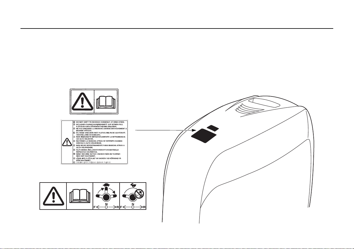
2. SAFETY LABEL LOCATIONS
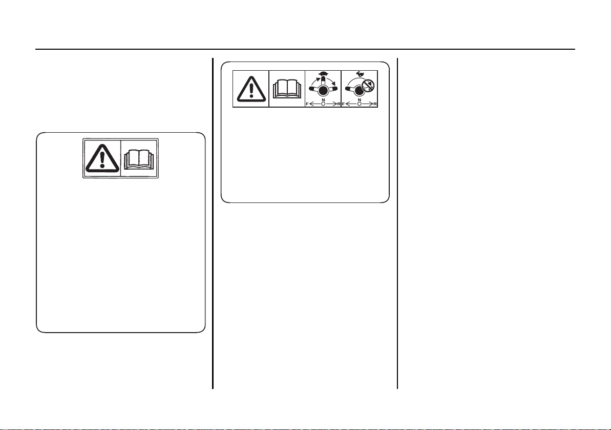
READ OWNER’S MANUAL
(general export types: except european types )
READ OWNER’S MANUAL GEAR SHIFTING
(european types)
These labels are in the locations shown.
They warn you of potential hazards tha
Read the labels and safety notes and precautions described in this manual carefully.
If a label comes off or becomes hard to read, contact your TOHATSU outboard motor dealer for a replacement.
t can cause serious injury.
8
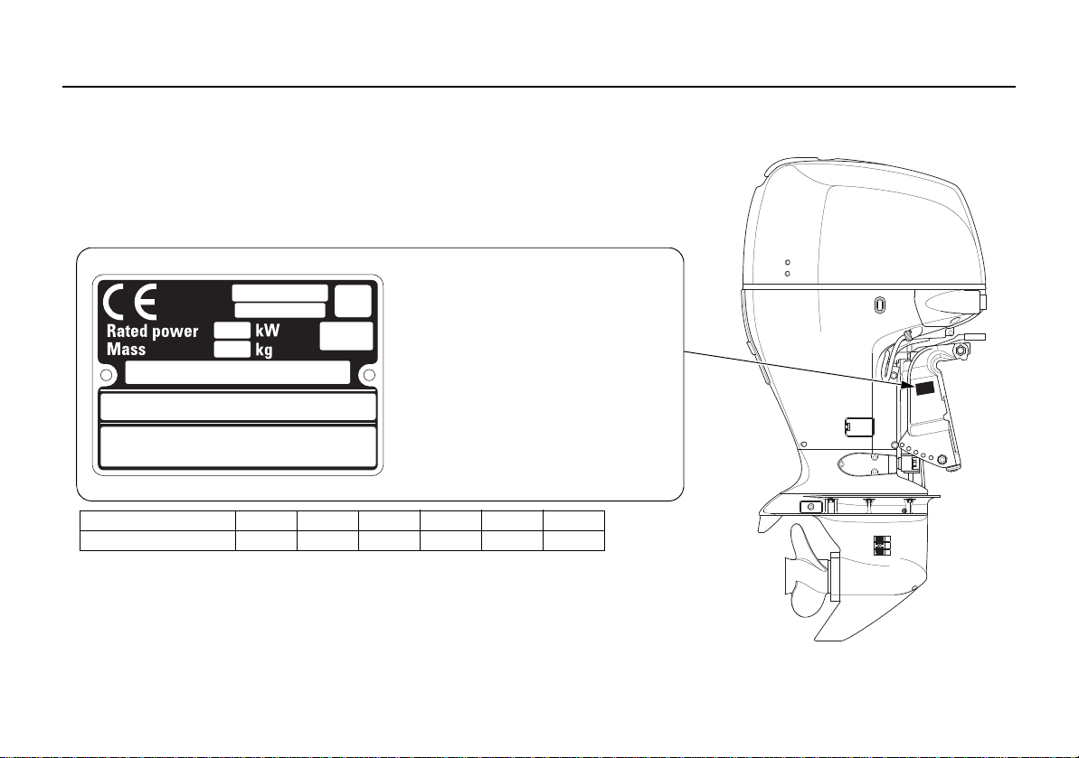
CE mark location [European types]
CE MARK
Name and address of manufacturer and authorized representative are written in the
“EC Declaration of Conformity” CONTENT OUTLINE in this Owner’s Manual.
Year code D E F G H J
Year of manufacture 2013 2014 2015 2016 2017 2018
(1) Model name
(2) Engine family name
(3) Year code
(4) Rated power
(5) Dry mass (weight) (with propeller,
without battery cable)
(6) Country of manufacture
(7) Frame number
(8) Manufacturer and address
(9) Name and address of authorized
representative
(1)
(2)
(3)
(4)
(5)
(6)
(7)
(8)
(9)
SAFETY LABEL LOCATIONS
9
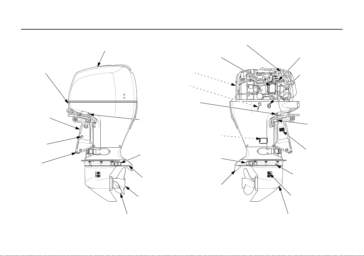
3. COMPONENT IDENTIFICATION
ENGINE COVER
ENGINE COVER
LATCH
STERN
BRACKET
MANUAL
RELIEF VALVE
ANODE
PROPELLER
ANTICAVITATION
PLATE
ANODE
COOLING WATER
CHECK HOLE
SPARK PLUG
OIL LEVEL
DIPSTICK
FLUSH PLUG
CONNECTOR
ENGINE OIL
DRAIN BOL T
(inside cover)
ANODE
TRIM TAB
JUNCTION BOX
(FUSES)
OIL FILLER CAP
INTERFACE
COUPLER
POWER TILT
SWITCH
TILT LOCK
LEVER
GEAR OIL DRAIN/FILL SCREW
EXHAUST PORT/
WATER OUTLET PORT
COOLING WATER
INTAKE PORT
GEAR OIL LEVEL
CHECK SCREW
FRAME SERIAL
NUMBER
10
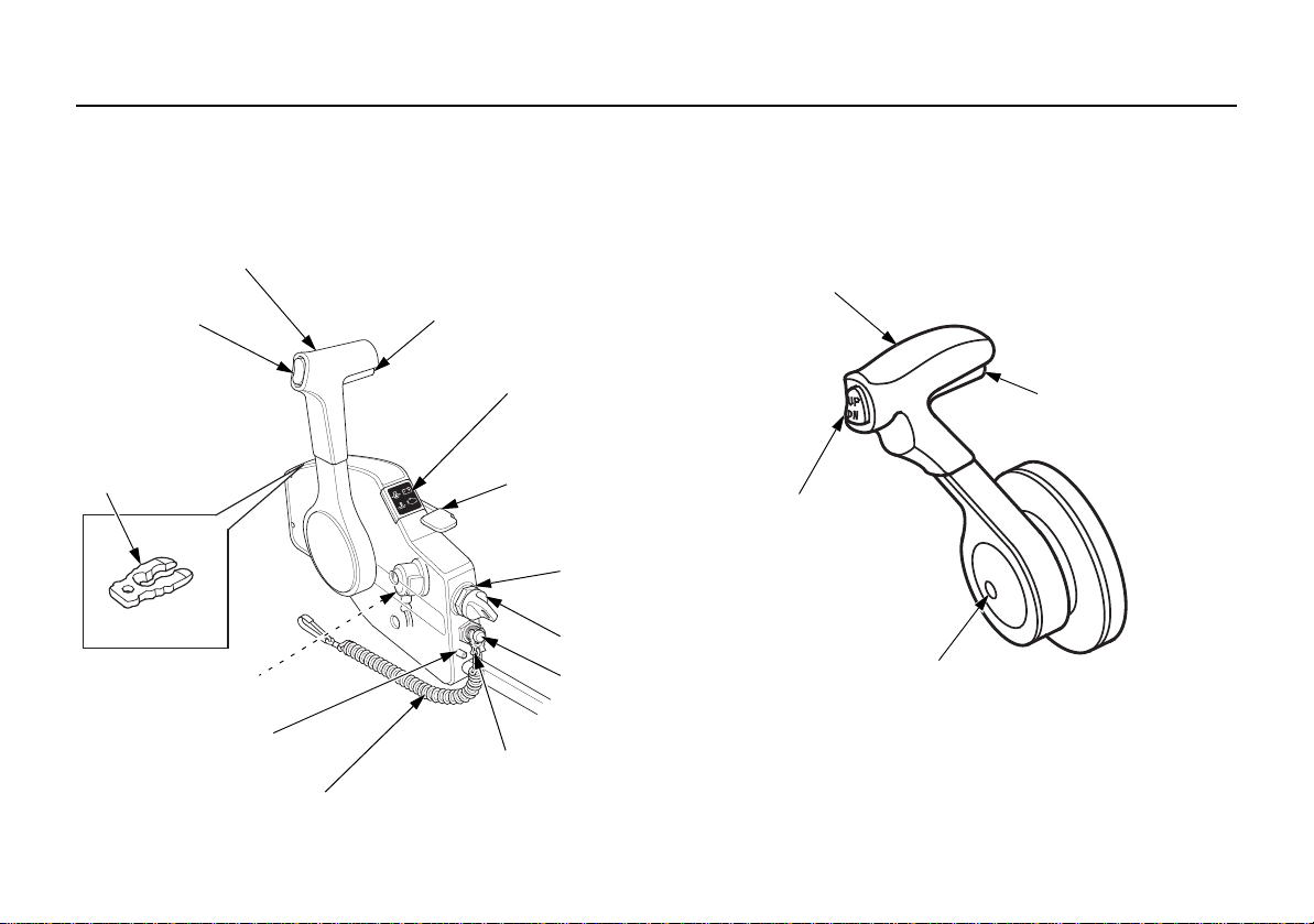
REMOTE CONTROL BOX (optional equipment)
SIDE-MOUNT TYPE (R1 type)
REMOTE CONTROL LEVER
NEUTRAL RELEASE
LEVER
SP ARE EMERGENCY
STOP SWITCH
CLIP
BUZZER
(inside)
CONTROL LEVER
FRICTION ADJUSTER
EMERGENCY STOP
SWITCH LANYARD
EMERGENCY STOP
SWITCH CLIP
INDICATORS
(Oil pressure, Overheat,
ACG, PGM
-FI)
FAST IDLE LEVER
ENGINE SWITCH
ENGINE SWITCH KEY
EMERGENCY STOP
SWITCH
FAST IDLE BUTTON
POWER TRIM/TIL T
SWITCH
PANEL-MOUNT TYPE (R2 type)
REMOTE CONTROL LEVER
POWER TRIM/TIL T
SWITCH
NEUTRAL RELEASE
LEVER
COMPONENT IDENTIFICATION
11
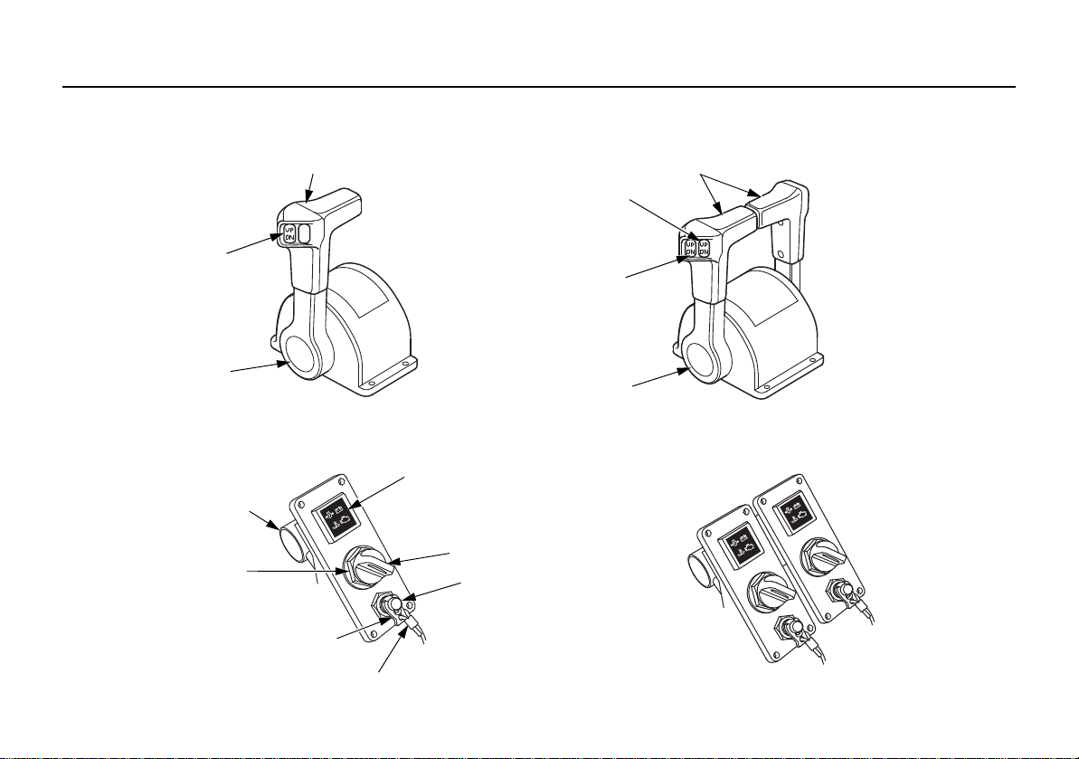
COMPONENT IDENTIFICATION
TOP-MOUNT TYPE (R3 type) (SINGLE OUTBOARD MOTOR TYPE)
REMOTE CONTROL LEVER
POWER TRIM/TIL T
SWITCH
FAST IDLE BUTTON
BUZZER
ENGINE
SWITCH
EMERGENCY STOP SWITCH LANYARD
INDICATORS
(Oil pressure, Overheat,
ACG, PGM
-FI)
ENGINE SWITCH KEY
EMERGENCY
STOP SWITCH
(DUAL OUTBOARD MOTOR TYPE)
REMOTE CONTROL LEVERS
POWER TRIM/TIL T
SWITCH (RIGHT)
POWER TRIM/TIL T
SWITCH (LEFT)
FAST IDLE BUTTON
(for TOP-MOUNT DUAL type)
SWITCH PANEL (optional equipment)
(for PANEL-MOUNT, TOP-MOUNT SINGLE type)
EMERGENCY STOP SWITCH CLIP
12
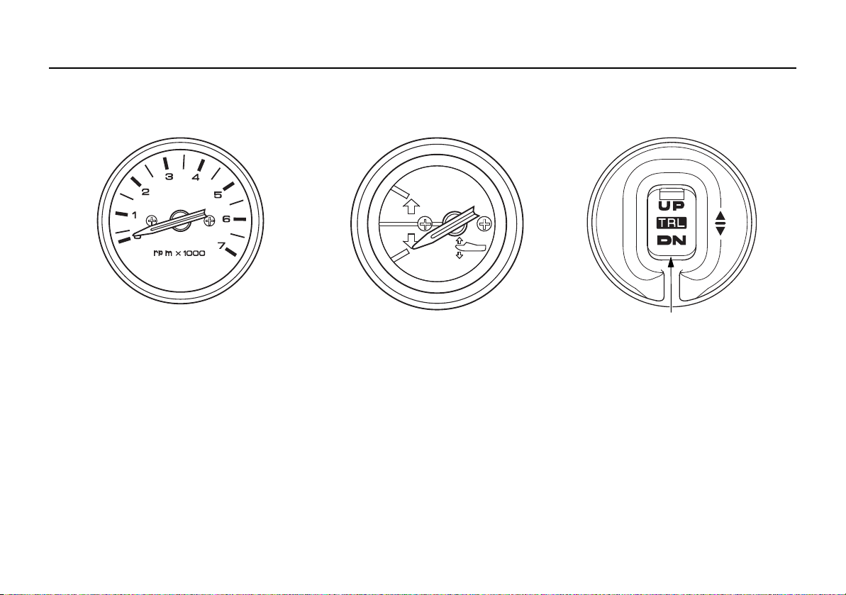
TACHOMETER
(optional equipment)
TRIM METER
(optional equipment)
TRL (T rolling) CONTROL SWITCH PANEL
(optional equipment)
TRL (Trolling) CONTROL SWITCH
(Common)
COMPONENT IDENTIFICATION
13
4. CONTROLS AND FEATURES
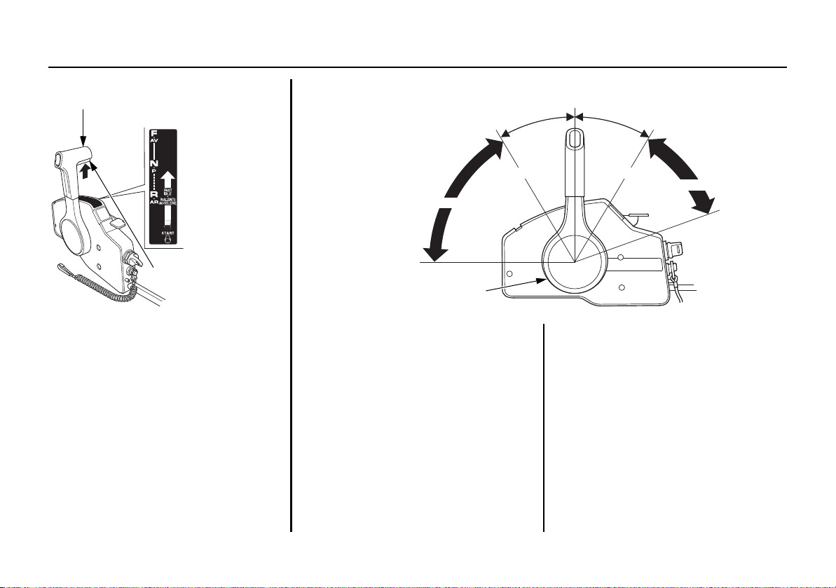
REMOTE CONTROL LEVER
FORWARD
NEUTRAL
REVERSE
NEUTRAL RELEASE
LEVER
NEUTRAL
30°
30°
FORWARD
REVERSE
SHIFT
SHIFT
MAXIMUM
REMOTE CONTROL LEVER
MAXIMUM
MINIMUM
MINIMUM
THROTTLE OPENING
THROTTLE OPENING
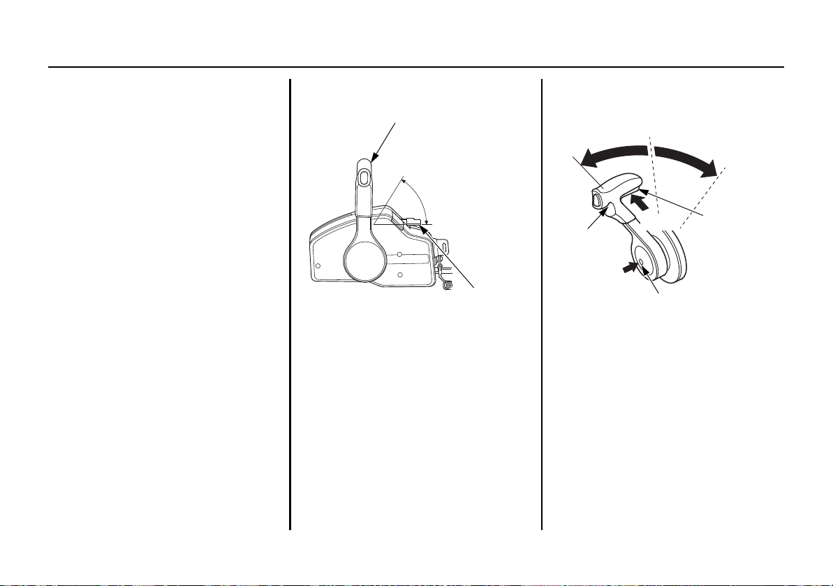
Remote Control Lever (R1 type)
Shifting gear into forward, reverse, or
neutral an
adjustment can be performed with the
remote control lever.
It is necessary to pull up the neutral
release lever to opera
control lever.
14
d the engine speed
te the remote
FORWARD:
Moving the lever to the F
ORWARD
position (i.e. approximately 30° from
the NEUTRAL position) engages the
gear into forward. Moving the lever
further from the FORWARD position
will increase the throttle opening and
the boat forward speed.
NEUTRAL:
Engine power is cut off from the
prope
ller.
REVERSE:
Movi
ng the lever to the REVERSE
position (i.e. approximately 30° from
the NEUTRAL position) engages the
gear into reverse. Moving the lever
further from the REVERSE position
will increase the throttle opening and
the boat reverse speed.
CONTROLS AND FEATURES
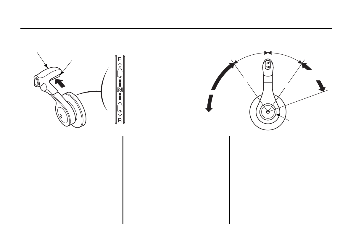
Remote Control Lever (R2 type)
NEUTRAL
RELEASE
LEVER
FORWARD
NEUTRAL
REVERSE
MAXIMUM
FORWARD
35°
NEUTRAL
35°
REVERSE
SHIFT
SHIFT
MAXIMUM
THROTTLE OPENING
REMOTE CONTROL LEVER
THROTTLE
OPENING
MINIMUM
MINIMUM
REMOTE
CONTROL LEVER
Shifting gear into forward, reverse, or
neutral and the engine speed
adjustment can be performed with the
remote control lever.
It is necessary to pull up the neutral
release lever to operate the remote
control lever.
FORWARD:
Moving
position (i.e. approximately 35° from
the NEUTRAL position) engages the
gear into forward. Moving the lever
further from the FORWARD position
will increase the throttle opening and
the boat forward speed.
NEUTRAL:
Engine power is cut off from the
pro
the lever to the FORWARD
pe
ller.
REVERSE:
Moving the lever to the REVERSE
position (i.e. approximately 35° from
the NEUTRAL position) engages the
gear into reverse. Moving the lever
further from the REVERSE position
will increase the throttle opening and
the boat reverse speed.
15
CONTROLS AND FEATURES
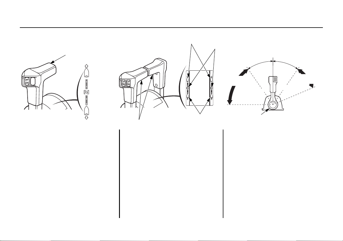
Remote Control Lever (R3 type)
FORWARD
NEUTRAL
REVERSE
REMOTE CONTROL LEVER
(DUAL TYPE)(SINGLE TYPE)
FORWARD
NEUTRAL
REVERSE
NEUTRAL
35°
35°
FORWARD
SHIFT
SHIFT
REMOTE CONTROL LEVER
MAXIMUM
REMOTE CONTROL
LEVER
MAXIMUM
REVERSE
THROTTLE
OPENING
THROTTLE
OPENING
MINIMUM
MINIMUM
Shifting gear into forward, reverse, or neutral and the engine speed adjustment can be performed with the remote control lever.
16
FORWARD:
Moving the lever to the FORWARD
position (i.e. approximately 35° from
NEUTRAL position) engages the
the
gear into forward. Moving the lever
further from the FORWARD position
will increase the throttle opening and
the boat forward speed.
NEUTRAL:
Engine power is cut off from the
ller.
prope
REVERSE:
Moving the lever to the REVERSE
position (i.e. approximately 35° from
the NEUTRAL position) engages the
gear into reverse. Moving the lever
further from the REVERSE position
will increase the throttle opening and
the boat reverse speed.
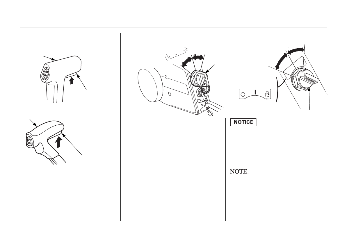
Neutral Release Lever
(R1 type)
REMOTE CONTROL LEVER
NEUTRAL
RELEASE LEVER
(R2 type)
REMOTE CONTROL LEVER
NEUTRAL
RELEASE LEVER
Engine Switch
START
ENGINE
SWITCH KEY
(R2, R3 types)
OFF
ON
OFF
START
ENGINE SWITCH KEY
START
(R1 type)
OFF
ON
ON
The neutral release lever is set on the
remote control lever to prevent an
accidental operation of the remote
control lever.
The remote control lever does not
operate unless it i
s moved while
pulling the neutral release lever up.
CONTROLS AND FEATURES
This remote control is equipped with
an automotive type engine switch.
On the side-mount type (R1 type), the
engine switch locates on your side
near the remote control box.
On the panel-mount type (R2 type)
and the top-mount type (R3 type), the
engine switch locates at the center of
the control panel.
Key positions:
START: to start the engine.
ON: to run the engine after
OFF: to stop the engine
starting.
(IGNITION OFF).
Do not leave the engine switch (ignition switch) ON (key in ON position) when the engine is not running as the battery will discharge.
The starter motor will not work
unless the remote control lever is in
the NEUTRAL position, and the clip
is in the emergency stop switch.
17
CONTROLS AND FEATURES
NEUTRAL
REMOTE CONTROL
LEVER
F AST IDLE LEVER
MAXIMUM
FA ST IDLE
LOWEST
POSITION
NEUTRAL
FAST IDLE BUTTON
REVERSE
REMOTE
CONTROL
LEVER
NEUTRAL
RELEASE
LEVER
Push
Pull up
FORWARD
Fast Idle Lever (R1 type)/Fast Idle
Button (R2, R3 types)
The fast idle lever/fast idle button is
only needed for starting carbure
outboard model. The BFT115A/
150A models use programmed fuel
injection so, this lever will not be
needed for starting.
After the engine starts and if the
outside temperature is bel
(41°F), the fast idle lever/fast idle
button can be used to accelerate
engine warm up.
18
ted
ow 5°C
<Fast Idle Lever>
(R1 type)
The fast
unless the remote control leve
idle lever will not move
r
is in
the NEUTRAL position. Conversely,
the remote control lever will not
move unless the fast idle lever is in
the lowest position.
Lower the fast idle lever to the lowest position to decrease the fast idle.
<Fast Idle
Button>
(R2 type)
Pushing the fast idle button, turn the
remote control lever forward. Keep
turning the
lever forward. The
throttle
opens and the engine speed increases
after the lever passed the shift point.
Note that the gearshift mechanism
does not function when the fast idle
button is pushed once and then
released after the remote control lever
is moved.
The control lever does not operate
unless the neutral release lever is
pulled.
<Fast Idle Button>
(R3 type)
NEUTRAL
REMOTE
CONTROL
LEVER
FAST IDLE BUTTON
FORWARD
REVERSE
Push
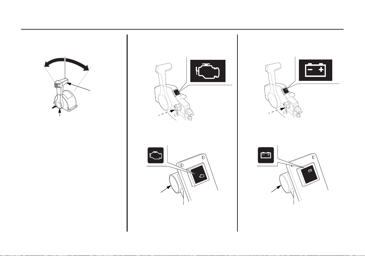
PGM-FI Indicator/Buzzer
(side-mount type)
(RED)
(RED)
PGM-FI
INDICATOR
BUZZER
(panel-mount/top-mount types)
PGM-FI
INDICATOR
BUZZER
ACG Indicator/Buzzer
(side-mount type)
(RED)
(RED)
BUZZER
ACG
INDICATOR
(panel-mount/top-mount types)
ACG
INDICATOR
BUZZER
CONTROLS AND FEATURES
Use the fast idle button and the
remote control lever to adjust the
engine speed without gearshift when
warming up the engine.
Pushing the fast idle button, turn the
remote control lever forward. Keep
turning the lever forward. The
opens and the engine speed increases
after the lever passed the shift point.
Note that the gearshift mechanism
does not function when the fast idle
button is pushed once and then
released after the remote control lever
is moved.
throttle
The PGM-FI indicator turns on and
the buz
zer sounds
when the engine
control system is faulty.
The ACG indicator turns on and the
buzzer s
ounds when the charging
system is faulty.
19
CONTROLS AND FEATURES
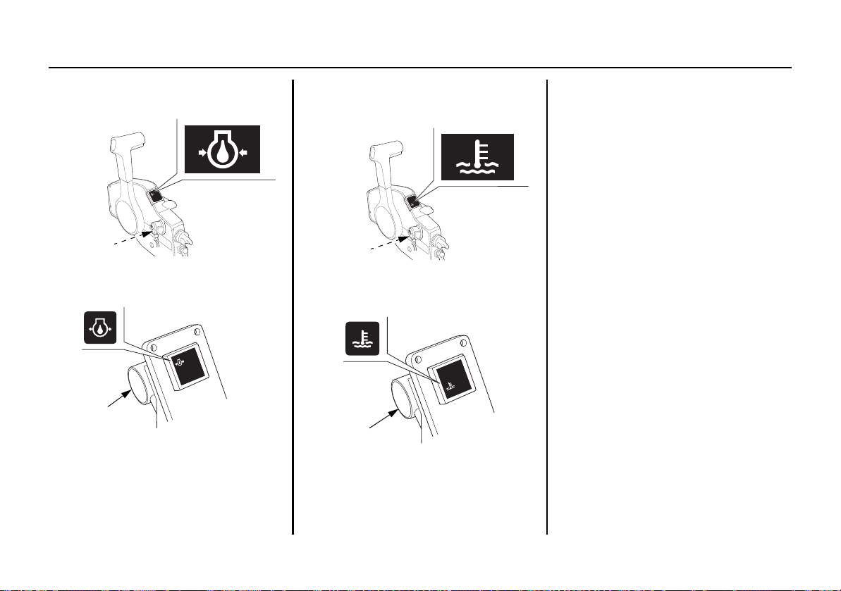
Oil Pressure Indicator/Buzzer
(side-mount type)
(GREEN)
OIL PRESSURE
INDICATOR
(panel-mount/top-mount types)
OIL PRESSURE
INDICATOR
(GREEN)
BUZZER
BUZZER
Overheat Indicator/Buzzer
(side-mount type)
(RED)
(RED)
BUZZER
OVERHEAT
INDICATOR
(panel-mount/top-mount types)
OVERHEAT
INDICATOR
BUZZER
The oil pressure indicator turns off
and the buzzer sounds when the oil
level is low and/or the engine
lubrication system is faulty.
The engine speed slows down
gradually this time.
The overheat indicator turns on and
the buzzer sounds
when the engine
cooling circuit is faulty. The engine
speed slows down this time.
Water Separator Buzzer
The water separator buzzer sounds
water has accumulated in the
n
whe
water separator.
20
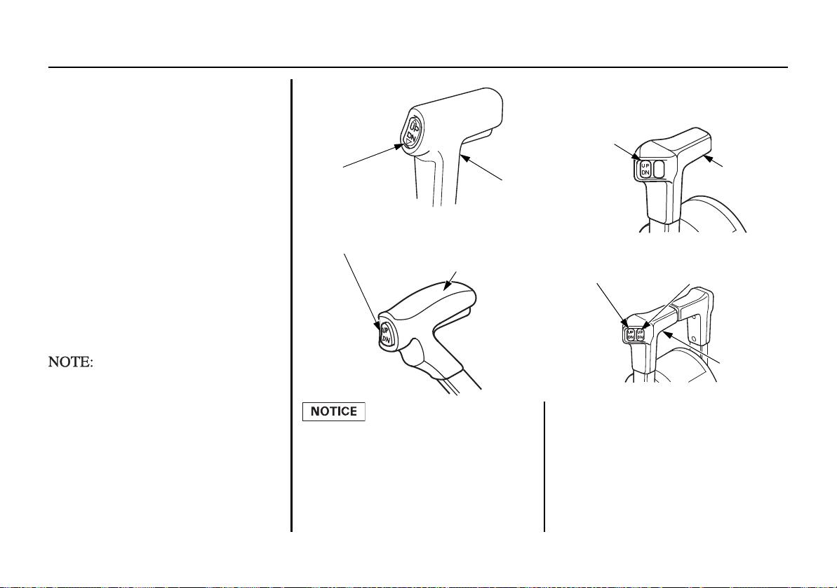
Power Trim/Tilt Switch
(R1 type)
REMOTE CONTROL
LEVER
POWER TRIM/
TILT SWITCH
(R2 type)
(DUAL TYPE)
POWER TRIM/TILT SWITCH
(LEFT)
(RIGHT)
POWER TRIM/
TILT SWITCH
(SINGLE TYPE)
(R3 type)
POWER TRIM/TILT SWITCH
REMOTE CONTROL LEVER
REMOTE
CONTROL
LEVER
REMOTE
CONTROL
LEVER
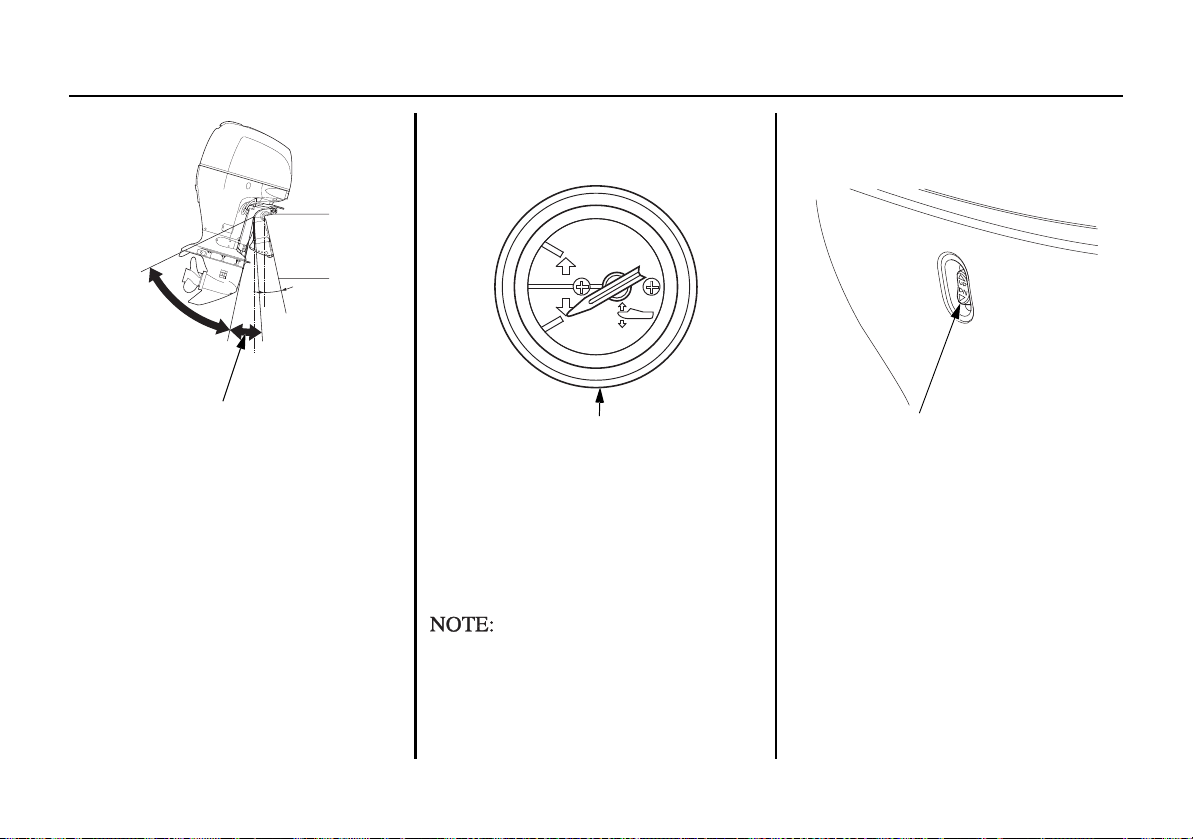
Power Trim
Press the power trim/tilt switch on the
remote control lever to adjust the
outboard motor trim angle of – 4° to
16° to maintain proper boat trim. The
power trim/tilt switch can be operated
while the boat is under way or while
stopped.
By using the power trim/tilt switch
the operator can change the trim
angle of the outboard motor to
achieve maximum boat acceleration,
speed, stability and maintain
optimum fuel consumption.
The outboard motor trim angle of
– 4° to 16° is the angle when the
outboard motor is installed on the
boat at 12°.
Excessive trim/tilt angle during
operation can cause the propeller
to raise out of the water and cause
propeller ventilation and engine
over-revving. Excessive trim/tilt
angle can also damage the water
pump.
CONTROLS AND FEATURES
21
CONTROLS AND FEATURES
72°
0°
0°
12°
(VERTICAL LINE)
TRIM ANGLE
(when transom angle is 12°)
– 4°
TILT ANGLE
16°
TRIM METER
POWER TILT SWITCH
Power Tilt
Press the power trim/tilt switch to
st the outboard motor tilt angle of
adju
16° to 72°.
By using the power trim/tilt switch
the operator can change the tilt angle
of the outboard motor for shallow
water operation, beaching, launching
from a trailer, or mooring.
Please tilt up simultaneously, when
you mount the dual type outboard
motor.
22
Trim Meter
(optional equipment)
The trim meter has a range of – 4° to
n
d indicates the trim angle of the
16° a
outboard motor. Refer to the trim
meter when using the power trim/tilt
switch to achieve proper boat
performance.
The outboard motor trim angle of
– 4° to 16° is the angle when the
outboard motor is installed on the
boat at 12°.
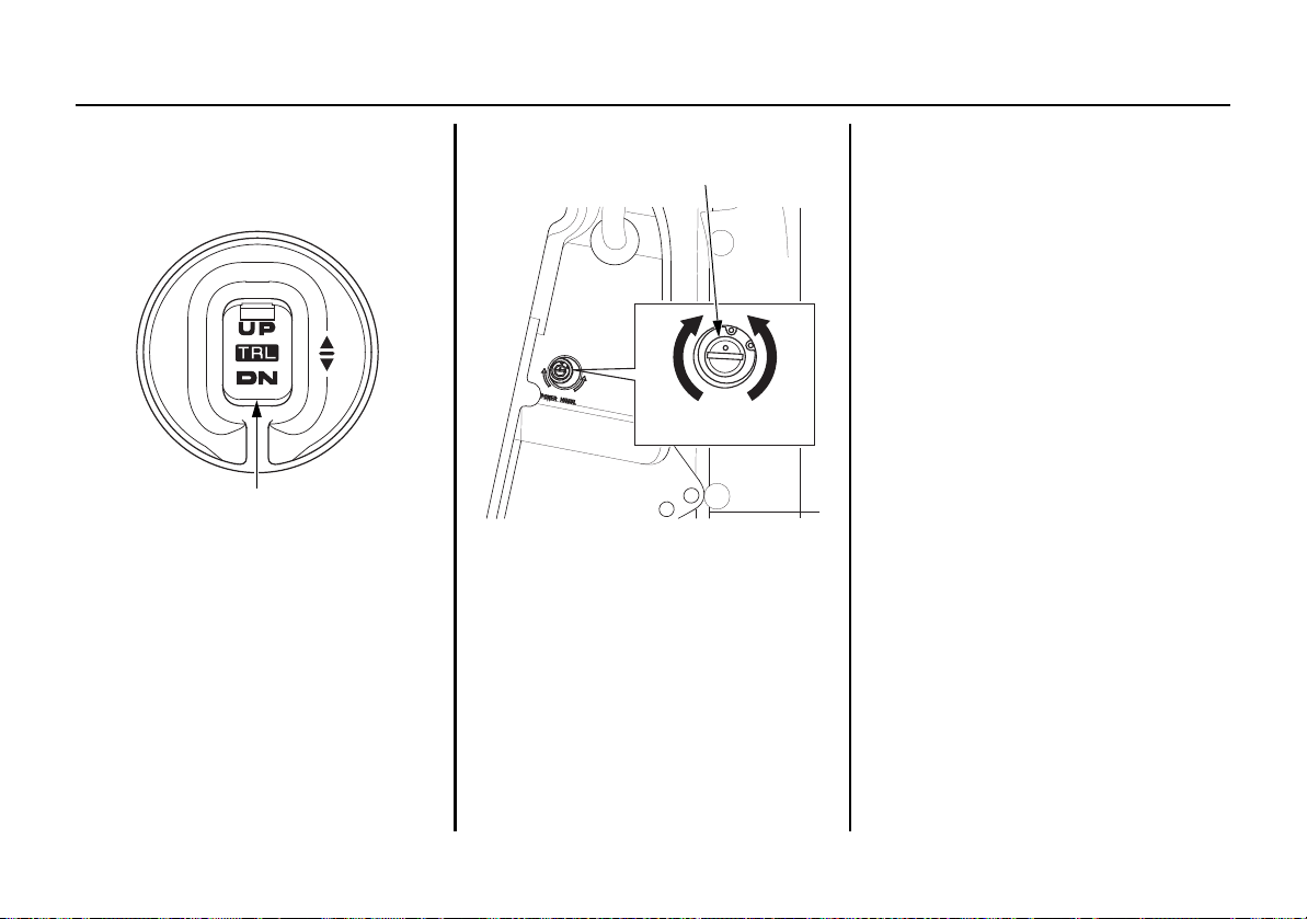
Power Tilt Switch
(outboard motor pan)
The power tilt switch located on the
ard motor pan is a convenience
outbo
switch for tilting the outboard motor
for trailering, or performing outboard
maintenance. This power tilt switch
should only be operated with the boat
being stopped and engine off.
CONTROLS AND FEATURES
TRL (Trolling) CONTROL SWITCH
MANUAL RELIEF VALVE
POWER
(To fix)
MANUAL
(To release)
TRL (Trolling) Control Switch
Panel
(optional equipment)
The engine speed can be adjusted
with the tr
olling control swit
ch when
in trolling mode.
If you press and hold the TRL control
switch while cruising with
the throttle
closed, the mode changes to trolling
mode.
Manual Relief Valve
If the power trim/tilt switch will not
tilt the outboard
motor, the outboard
motor can be manually tilted up or
down by opening the manual relief
valve. To tilt the outboard motor
manually , turn the manual relief valve
under the left stern bracket no more
than 1 or 2 turns counterclockwise
using a screwdriver.
After tilting the outboard motor, turn
e
the manual relief valve cloc
kwis
securely.
Check that no person is under the
outboard motor before carrying out
this position because
if the manual
relief valve is loosened (turned
counterclockwise) when the outboard
motor is tilted up, the outboard motor
will suddenly tilt down.
The manual relief valve must be
d
tightene
securely before operating
the outboard motor or the outboard
motor could tilt up when operating in
reverse.
23

CONTROLS AND FEATURES
(R1 type)
STOP
STOP
EMERGENCY STOP SWITCH
(R2, R3 types)
EMERGENCY STOP SWITCH
EMERGENCY STOP
SWITCH LANYARD
EMERGENCY STOP SWITCH CLIP
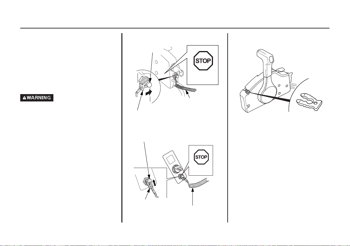
Emergency Stop Switch
The emergency stop switch lanyard is
provided to stop the engine
immediately
in the event the operator
should fall overboard or away from
the controls.
Emergency Stop Switch Lanyard/
Clip
The emergency stop switch clip must
e engaged with the engine stop
b
switch or the engine will not start.
When the emergency stop switch clip
becomes disengaged with the
emergency stop switch the engine
will stop immediately.
24
CONTROLS AND FEATURES
(R1 type)
STOP
STOP
EMERGENCY STOP
SWITCH CLIP
EMERGENCY STOP
SWITCH LANYARD
EMERGENCY
STOP SWITCH
EMERGENCY STOP
SWITCH CLIP
(R2, R3 types)
EMERGENCY STOP SWITCH
EMERGENCY STOP
SWITCH LANYARD
SPARE EMERGENCY
STOP SWITCH CLIP
(R1 type)
For the sake of the operator’s and the
passenger’s safety, be sure to set the
emergency stop switch clip located at
one end of the emergency stop switch
lanyard with the emergency stop
switch. Attach the other end of the
emergency stop switch lanyard
securely to the operator.
If the emergency stop switch
lanyard is not set, the boat might
run out of control when the
operator, for example, falls
overboard and is not able to
operate the outboard motor.
Spare Emergency Stop Switch Clip
A spare emergency stop switch clip is
ovided on the remote control box.
pr
(R2, R3 types)
A spare emergency stop switch clip
does not come wi
th R2, R3 type.
A spare emergency stop switch clip
is available from your outboard motor
aler.
de
A spare emergency stop switch clip
stored in the tool bag (see page
can be
82).
25
CONTROLS AND FEATURES
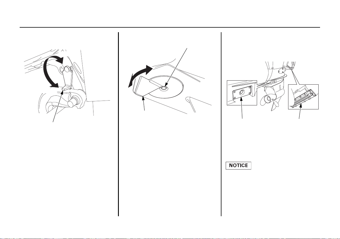
TILT LOCK LEVER
LOCK
FREE
TIGHTENING BOLT
TRIM TAB
ANODE
(each side)
ANODE
(stern bracket)
Tilt Lock Lever
Use the tilt lock lever to raise the
outboard motor and lock it i
position when the boat is moored or
anchored for a long time.
n the
Tilt the outboard motor as far as it
goes and move the l
ock lever in the
locking direction.
Trim Tab
If the steering wheel is pulled to the
side while running at full speed,
adj
ust the trim tab so that the boat
runs straight ahead.
Loosen the tightening bolt and turn
the trim tab right or left to adjust (see
ge 69).
pa
Anode
The anode metal is a sacrificed metal
which protects th
e outboard motor
from corrosion.
Do not paint the anode. It
deteriorates the function of the
anode metal, which can lead to rust
and corrosion damage to the
outboard motor.
26
CONTROLS AND FEATURES
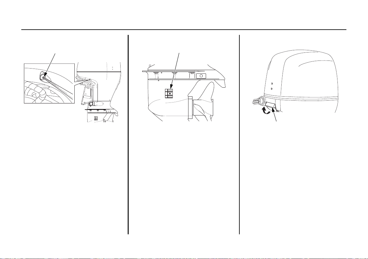
COOLING WATER CHECK HOLE
COOLING WATER INTAKE PORT
(each side)
ENGINE COVER LATCH
Cooling Water Check Hole
The cooling water is checked here to
see whether it is circulating inside the
en
gine properly.
After starting the engine, check at the
cooling water check hole whether the
cooling water
the engine.
is circulating through
Cooling Water Intake Port
The engine cooling water is drawn
into the engine through
this port.
Engine Cover Latch
Pull the engine cover latch to remove
gine cover.
the en
27
 Loading...