

TOHATSU 200 Series, BF175AK3, 225A Series, BF200AK3, BF225AK3 Service Manual

BFT
200/225A
OB No.62ZY300Z
14-01 NB

Introduction
Before reading this manual
Thisservicemanualprovidesinformationthatisneededforinspection,serviceandrepairof
applicableoutboardmotors.Forourcustomers'safeandcomfortableuseoftheproductsfor
longterm,itisessentialtomaintaintheperformanceandqualityoftheoutboardmotors.To
ensure this, the maintenance and service have to be done properly by service technicians
with fundamental knowledge and skills. This manual is utilized so that our customers can
alwaysusetheiroutboardmotorwithfullsatisfaction.
As this document contains information from the Honda Motor's Service Manual, the
documentcontainsinformationaboutmodelsthatarenotsoldbyourcompany.Additionally,
themodelnamesandpartnumbersofthespecialtoolsmentionedinthisdocumentarethe
namesandnumbers usedbyHondaMotor Co.,Ltd.Please alter themodelnames andpart
numbersasfollows.
Change model names with "BF" to "BFT".
Example: BF*** -> BFT***
Add "HCO-" at the beginning of part numbers of special tools.
Example: 07GD-0010100-OS -> HCO-07GD-0010100-OS

Introduction
Avant de lire le présent manuel
Le présent manuel d’entretien fournit les informations nécessaires au contrôle, à l’utilisation et à la réparation
des moteurs hors-bords concernés. Pour une utilisation de nos produits par nos clients, à long terme, en toute
sécurité et tout confort, il est capital de veiller à maintenir les performances et la qualité du hors-bord. Pour
garantir ce point, l’entretien et la maintenance doivent être assurés en bonne et due forme par des techniciens
en entretien et réparation disposant des connaissances et compétences clés. Le présent manuel est prévu pour
que nos clients puissent toujours utiliser leur moteur hors-bord pour leur plus grande satisfaction.
Ce document contient des informations provenant du manuel de réparation des moteurs Honda, mais il contient
aussi des informations sur des modèles qui ne sont pas vendus par notre société. De plus, les noms de modèle
et les numéros de pièce des outils spéciaux mentionnés dans ce document sont les noms et les numéros
utilisés par Honda Motor Co., Ltd. Veuillez modifier les noms de modèles et les numéros de pièces de la façon
suivante :
Changer les noms de modèle comprenant "BF" en "BFT".
Exemple: BF *** -> BFT ***
Ajouter "HCO-" au début des numéros de pièce des outils spéciaux.
Exemple: 07GD-0010100-OS -> HCO-07GD-0010100-OS

Introducción
Antes de leer este manual
Este manual de servicio brinda la información que se requiere para la inspección, el servicio y la reparación
de los correspondientes motores fuera de borda. Para que nuestros clientes puedan utilizar los productos
durante largo tiempo de forma segura y cómoda, resulta fundamental mantener el desempeño y la calidad
de los motores fuera de borda. Para garantizar esto, el mantenimiento y el servicio deben ser ejecutados
correctamente por ténicos de mantenimiento con el conocimiento y las habilidades requeridas. La utilización de
este manual permitirá a nuestros clientes utilizar siempre su motor fuera de borda con plena satisfacción.
Debido a que este documento contiene información extraía del manual de servicio de Honda Motor, el mismo
contiene información acerca de modelos que no son vendidos por nuestra empresa. Adem s, los nombres de
los modelos y los núeros de piezas de las herramientas especiales mencionadas en este documento son los
nombres y núeros utilizados por Honda Motor Co., Ltd. Modifique los nombres de los modelos y los núeros de
piezas como se indica a continuación.
Cambie los nombres de los modelos con "BF" a "BFT".
Ejemplo: BF *** -> BFT ***
Añda "HCO-" al inicio de los núeros de piezas de las herramientas especiales.
Ejemplo: 07GD-0010100-OS -> HCO-07GD-0010100-OS

Einführung
Vor dem Durchlesen dieses Handbuchs
Dieses Service-Handbuch enthält die Information, die zur Inspektion, Service und Reparatur der jeweiligen
Außenbordmotoren benötigt wird. Zur Sicherheit unserer Kunden und für eine komfortable, langfristige
Benutzung der Produkte ist es unumgänglich, die Leistung und Qualität der Außenbordmotoren instand zu
halten. Um dies zu gewährleisten, müssen Wartung und Service von Fachkräften mit dem entsprechenden
Wissen und Fähigkeiten durchgeführt werden. Dieses Handbuch wird genutzt, damit unsere Kunden ihren
Außenbordmotor zur vollen Zufriedenheit benutzen können.
Da dieses Dokument Information des Honda Motor Service-Handbuchs enthält, findet man auch Information
über Modelle, die nicht von unserem Unternehmen verkauft werden. Des Weiteren werden die in diesem
Dokument erwähnten Modellbezeichnungen und Teilenummern von Spezialwerkzeugen von Honda Motor Co.,
Ltd benutzt. Die Modellbezeichnungen und Teilenummern wie folgt abändern:
Modellbezeichnungen "BF" in "BFT" abändern.
Beispiel: BF*** -> BFT***
"HCO" vor die Teilenummern der Spezialwerkzeuge setzen.
Beispiel: 07GD-0010100-OS -> HCO-07GD-0010100-OS
How to use this manual
How to use this manual
A Few Words About Safety
SERVICE INFORMATION
The service and repair information contained in this manual is intended for use by qualified, professional technicians. Attempting
service or repairs without the proper training, tools, and equipment could cause injury to you and/or others. It could also damage
this Honda product or create an unsafe condition.
This manual describes the proper methods and procedures for performing service, maintenance, and repairs. Some procedures
require the use of special tools. Any person who intends to use a replacement part, service procedure, or a tool that is not
recommended by Honda must determine the risks to their personal safety and the safe operation of this product.
If you need to replace a part, use Honda Genuine parts with the correct part number or an equivalent part. We strongly recommend
that you do not use replacement parts of inferior quality.
For Your Customer’s Safety
Proper service and maintenance are essential to the customer’s safety and the reliability of this product. Any error or oversight
while servicing this product can result in faulty operation, damage to the product, or injury to others.
Improper service or repairs can create an unsafe
condition that can cause your customer or others to
be seriously hurt or killed.
Follow the procedures and precautions in this manual and other service materials carefully.
For Your Safety
Because this manual is intended for the professional service technician, we do not provide warnings about many basic shop safety
practices (e.g., Hot parts-wear gloves). If you have not received shop safety training or do not feel confident about your knowledge
of safe servicing practices, we recommend that you do not attempt to perform the procedures described in this manual.
Some of the most important general service safety precautions are given below. However, we cannot warn you of every
conceivable hazard that can arise in performing service and repair procedures. Only you can decide whether or not you should
perform a given task.
Failure to properly follow instructions and precautions can cause you to be seriously hurt or killed.
Follow the procedures and precautions in this manual carefully.
Important Safety Precautions
Make sure you have a clear understanding of all basic shop safety practices and that you are wearing appropriate clothing and
using safety equipment. When performing any service task, be especially careful of the following:
• Read all of the instructions before you begin, and make sure you have the tools, the replacement or repair parts, and the skills
required to perform the tasks safely and completely.
• Protect your eyes by using proper safety glasses, goggles, or face shields anytime you hammer, drill, grind, or work around
pressurized air, pressurized liquids, springs, or other stored-energy components. If there is any doubt, put on eye protection.
• Use other protective wear when necessary, for example gloves or safety shoes. Handling hot or sharp parts can cause severe
burns or cuts. Before you grab something that looks like it can hurt you, stop and put on gloves.
• Protect yourself and others whenever you have equipment hoisted in the air. Anytime you lift this product with a hoist, make sure
that the hoist hook is securely attached to the product.
Make sure the engine is off before you begin any servicing procedures, unless the instruction tells you to do otherwise. This will
help eliminate several potential hazards:
• Carbon monoxide poisoning from engine exhaust. Be sure there is adequate ventilation whenever you run the engine.
• Burns from hot parts. Let the engine and exhaust system cool before working in those areas.
• Injury from moving parts. If the instruction tells you to run the engine, be sure your hands, fingers, and clothing are out of the
way.
Gasoline vapors and hydrogen gasses from batteries are explosive. To reduce the possibility of a fire or explosion, be careful when
working around gasoline or batteries.
• Use only a nonflammable solvent, not gasoline, to clean parts.
• Never store gasoline in an open container.
• Keep all cigarettes, sparks, and flames away from the battery and all fuel-related parts.
0-1
INTRODUCTION
This supplement covers the construction, function, and
servicing procedures of the Honda BF175AK3/200AK3/
225AK3 outboard motor.
For service information that is not covered in this
supplement, please refer to the BF175AK1/200AK1/
225AK1 (62ZY300) base shop manual.
All information contained in this manual is based on the
latest product information available at the time of
printing. We reserve the right to make changes at
anytime without notice.
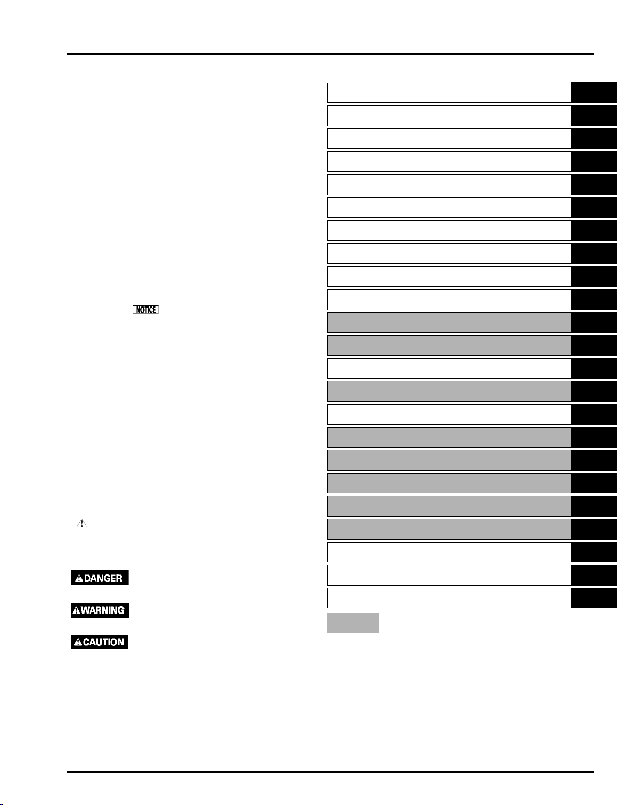
How to use this manual
GENERAL INFORMATION
SERVICE INFORMATION
MAINTENANCE
TROUBLESHOOTING
FUEL SYSTEM
ENGINE COVER/COVER LOCK
1
2
3
4
5
6
No part of this publication may be reproduced, stored in
a retrieval system, or transmitted, in any form, by any
means, electronic, mechanical, photocopying,
recording, or otherwise, without prior written permission
of the publisher. This includes text, figures, and tables.
As you read this manual, you will find information that is
preceded by a symbol. The purpose of this
message is to help prevent damage to this Honda
product, other property, or the environment.
SAFETY MESSAGES
Your safety and the safety of others are very important.
To help you make informed decisions, we have
provided safety messages and other safety information
throughout this manual. Of course, it is not practical or
possible to warn you about all the hazards associated
with servicing these products. You must use your own
good judgement.
You will find important safety information in a variety of
forms, including:
· Safety Labels – on the product.
· Safety Messages – preceded by a safety alert symbol
and one of three signal words, DANGER,
WARNING, or CAUTION.
These signal words mean:
You WILL be KILLED or SERIOUSLY
HURT if you don’t follow instructions.
You CAN be KILLED or SERIOUSLY
HURT if you don’t follow instructions.
You CAN be HURT if you don’t follow
instructions.
CHARGING SYSTEM
IGNITION SYSTEM
STARTING SYSTEM
OTHER ELECTRICAL
COOLING SYSTEM
LUBRICATION SYSTEM
ENGINE REMOVAL/INSTALLATION
CYLINDER HEAD
CYLINDER BLOCK
GEAR CASE (STANDARD ROTATION)
GEAR CASE (COUNTER ROTATION)
MOUNT
TRIM/TILT
CONTROLS
TECHNICAL FEATURES
WIRING DIAGRAMS
INDEX
The marked sections contain no changes.
They are not covered in this supplement.
7
8
9
10
11
12
13
14
15
16
17
18
19
20
21
22
· Instructions – how to service these products correctly
and safely.
© Honda Motor Co., Ltd.
SERVICE PUBLICATION OFFICE
Date of Issue: May 2013
0-2
i

MEMO

dummytext
SPECIFICATIONS ·········································1-2
1. GENERAL INFORMATION
1
1-1

dummyheaddummyhead
GENERAL INFORMATION
GENERAL INFORMATION
SPECIFICATIONS
TYPE DESCRIPTION
It may be necessary to refer to this chart for reference purposes when reading this manual.
Model BF175AK3
Type XD/XT/XU XXD/XXT
Shaft Length type XL XXL
Counter Rotation –
Remote control
Power Trim/Tilt
Tachometer ( )
Trim meter ( )
XL: Extra long, XXL: Extra-extra long
( ): Optional part
The power trim/tilt type motors use an electric/hydraulic power cylinder to trim or tilt the motor.
Model BF200AK3
Type LU XU/XT/XD XCU/XCT/XCD XXU/XXT/XXD
Shaft Length type L XL XXL
Counter Rotation – – –
Remote control
Power Trim/Tilt
Tachometer ( )
Trim meter ( )
XL: Extra long, XXL: Extra-extra long
( ): Optional part
The power trim/tilt type motors use an electric/hydraulic power cylinder to trim or tilt the motor.
Model BF225AK3
Type LU/LD XU/XD/XT XCU/XCD/
XCT
Shaft Length type L XL XXL
Counter Rotation – – –
Remote control
Power Trim/Tilt
Tachometer ( )
Trim meter ( )
XL: Extra long, XXL: Extra-extra long
( ): Optional part
The power trim/tilt type motors use an electric/hydraulic power cylinder to trim or tilt the motor.
XXU/XXT/
XXD
XXCU/
XXCT/XXCD
1-2

dummyheaddummyhead
GENERAL INFORMATION
DIMENSIONS AND WEIGHTS
Model BF175AK3
Description code BAJJ
Type XD/XT/XU XXD/XXT
Overall length 920 mm (36.2 in)
Overall width 625 mm (24.6 in)
Overall height 1,797 mm (70.7 in) 1,924 mm (75.7 in)
Dry weight (*1) 270 kg (595 lbs) 275 kg (606 lbs)
Operating weight
(including oil) (*1)
*1: With propeller mounted.
Aluminum type 3.0 kg (6.6 lbs)
Model BF200AK3
Description code BAEJ BAFJ BAEJ
Type LU XU/XT/XD XCU/XCT/XCD XXU/XXT/XXD
Overall length 920 mm (36.2 in)
Overall width 625 mm (24.6 in)
Overall height 1,670 mm
Dry weight (*1) 265 kg (584 lbs) 270 kg (595 lbs) 273 kg (602 lbs) 275 kg (606 lbs)
Operating weight
(including oil) (*1)
*1: With propeller mounted.
LU, XU, XT, XD, XXU, XXT and XXD types: Aluminum type 3.0 kg (6.6 lbs)
XCU, XCT and XCD types: Stainless type 6.0 kg (13.2 lbs)
(65.7 in)
274 kg (604 lbs) 279 kg (615 lbs) 282 kg (622 lbs) 284 kg (626 lbs)
279 kg (615 lbs) 284 kg (626 lbs)
1,797 mm (70.7 in)
1,924 mm
(75.7 in)
Model BF225AK3
Description code BAGJ BAHJ BAGJ BAHJ
Type LU/LD XU/XT/XD XCU/XCT/
XCD
Overall length 920 mm (36.2 in)
Overall width 625 mm (24.6 in)
Overall height 1,670 mm
(65.7 in)
Dry weight (*1) 267 kg
(589 lbs)
Operating weight
(including oil) (*1)
*1: With propeller mounted.
LU, LD, XU, XT, XD, XXU, XXT and XXD types: Aluminum type 3.0 kg (6.6 lbs)
XCU, XCT, XCD, XXCU, XXCT and XXCD types: Stainless type 6.0 kg (13.2 lbs)
276 kg
(608 lbs)
1,797 mm (70.7 in) 1,924 mm (75.7 in)
272 kg
(600 lbs)
281 kg
(619 lbs)
275 kg
(606 lbs)
284 kg
(626 lbs)
XXU/XXT/
XXD
277 kg
(611 lbs)
286 kg
(631 lbs)
XXCU/
XXCT/XXCD
280 kg
(617 lbs)
289 kg
(637 lbs)
1-3

dummyheaddummyhead
GENERAL INFORMATION
FRAME
Model BF175AK3
Type XD/XT/XU XXD/XXT
Transom height (*1) 635 mm (25.0 in) 762 mm (30.0 in)
Tilting angle (*1) 68°
Tilting stage Stageless
Trim angle (*1) – 4° to 16°
Swivel angle 30° right and left
*1: Transom angle is at 12°.
Model BF200AK3
Type LU XU/XCU/XT/
XCT/XD/XCD
Transom height (*1) 508 mm (20.0 in) 635 mm (25.0 in) 762 mm (30.0 in)
Tilting angle (*1) 68°
Tilting stage Stageless
Trim angle (*1) – 4° to 16°
Swivel angle 30° right and left
*1: Transom angle is at 12°.
XXU/XXT/XXD
Model BF225AK3
Type LU/LD XU/XCU/XT/
XCT/XD/XCD
Transom height (*1) 508 mm (20.0 in) 635 mm (25.0 in) 762 mm (30.0 in)
Tilting angle (*1) 68°
Tilting stage Stageless
Trim angle (*1) – 4° to 16°
Swivel angle 30° right and left
*1: Transom angle is at 12°.
XXU/XXCU/XXT/
XXCT/XXD/XXCD
NOISE AND VIBRATION
Model BF175AK3 BF200AK3 BF225AK3
Control system Remote control
Sound Pressure Level At
Operator’s Ear (2006/42/EC,
ICOMIA 39–94)
Uncertainty 1 dB (A)
Vibration (2006/42/EC, ICOMIA
38–94)
Reference to: ICOMIA Standard: as it specifies the engine operating conditions and measurement conditions.
78 dB (A) 79 dB (A)
Not Exceed 2.5 (m/s
2
) rms
1-4

dummyheaddummyhead
GENERAL INFORMATION
ENGINE
Model BF175AK3 BF200AK3 BF225AK3
Description code BEAJJ BEAEJ BEAGJ
Type 4-stroke, O.H.C., 6-cylinder
Displacement 3,471 cm
Bore x stroke 89.0 x 93.0 mm (3.50 x 3.66 in)
Rated power (*1) 128.7 kW (175 PS) 147.1 kW (200 PS) 165.5 kW (225 PS)
Maximum torque 265 N·m
Compression ratio 9.4 :1
Fuel consumption ratio
(at rated power)
Fuel consumption ratio
(at continuous maximum power)
Cooling system Forced water circulation by impeller pump with thermostat
Ignition system Fully transistorized, battery ignition
Ignition timing 0° at 650 min
Spark plug IZFR6K-11E (NGK)
Fuel supply system Programmed fuel injection
Fuel injection system Electronic control
Fuel injection nozzle Multi-point type
Fuel Unleaded gasoline with a pump octane rating of 86 or higher
Fuel pump Electric and mechanical plunger type
Lubrication system Pressure lubrication by trochoid pump
Lubrication capacity 8.8 liters (9.3 US qt, 7.7 Imp qt)
Starter system Electric starter
Stopping system Primary circuit ground
Exhaust system Underwater type
*1: at 5,500 min
-1
(rpm)
(27.0 kgf·m, 195 lbf·ft)
336 g/kW·h 337 g/kW·h 336 g/kW·h
349 g/kW·h 334 g/kW·h
[Without oil filter replacement: 7.6 liters (8.03 US qt, 6.69 Imp qt)]
[With oil filter replacement: 7.8 liters (8.24 US qt, 6.86 Imp qt)]
(29.8 kgf·m, 215 lbf·ft)
3
(211.7 cu in)
292 N·m
-1
(rpm) B.T.D.C.
295 N·m
(30.1 kgf·m, 218 lbf·ft)
1-5

dummyheaddummyhead
MEMO

dummytext
2. SERVICE INFORMATION
2
ENGINE & FRAME TORQUE VALUES ········2-2
CABLE/HARNESS ROUTING·······················2-3
TUBE ROUTING ·········································2-18
2-1

dummyheaddummyhead
SERVICE INFORMATION
SERVICE INFORMATION
ENGINE & FRAME TORQUE VALUES
OTHERS
Item
Power tilt relay mounting bolt/
washer
Fuse/relay junction box terminal bolt M6 x 1.0 8.5 0.87 6.3
Fuse/relay junction box mounting
bolt
Connector holder mounting bolt M6 x 1.0 5.0 0.51 3.7
Block fuse screw/washer M5 x 0.8 3.2 0.33 2.4
Plug maintenance cover special bolt M6 x 1.0 10 1.0 7
HO2S sealing bolt (*1) M10 x 1.25 10 1.0 7
*1: XT, XCT, XXT, XXCT type:
Do not remove the HO2S sealing bolt.
When installing the HO2S sealing bolt by mistake, tighten it to the specified torque at above list.
Thread Dia. and pitch Torque values
mm (in) N·m kgf·m lbf·ft
M6 x 1.0 5.0 0.51 3.7
M6 x 1.0 5.0 0.51 3.7
Remarks
2-2
dummyheaddummyhead
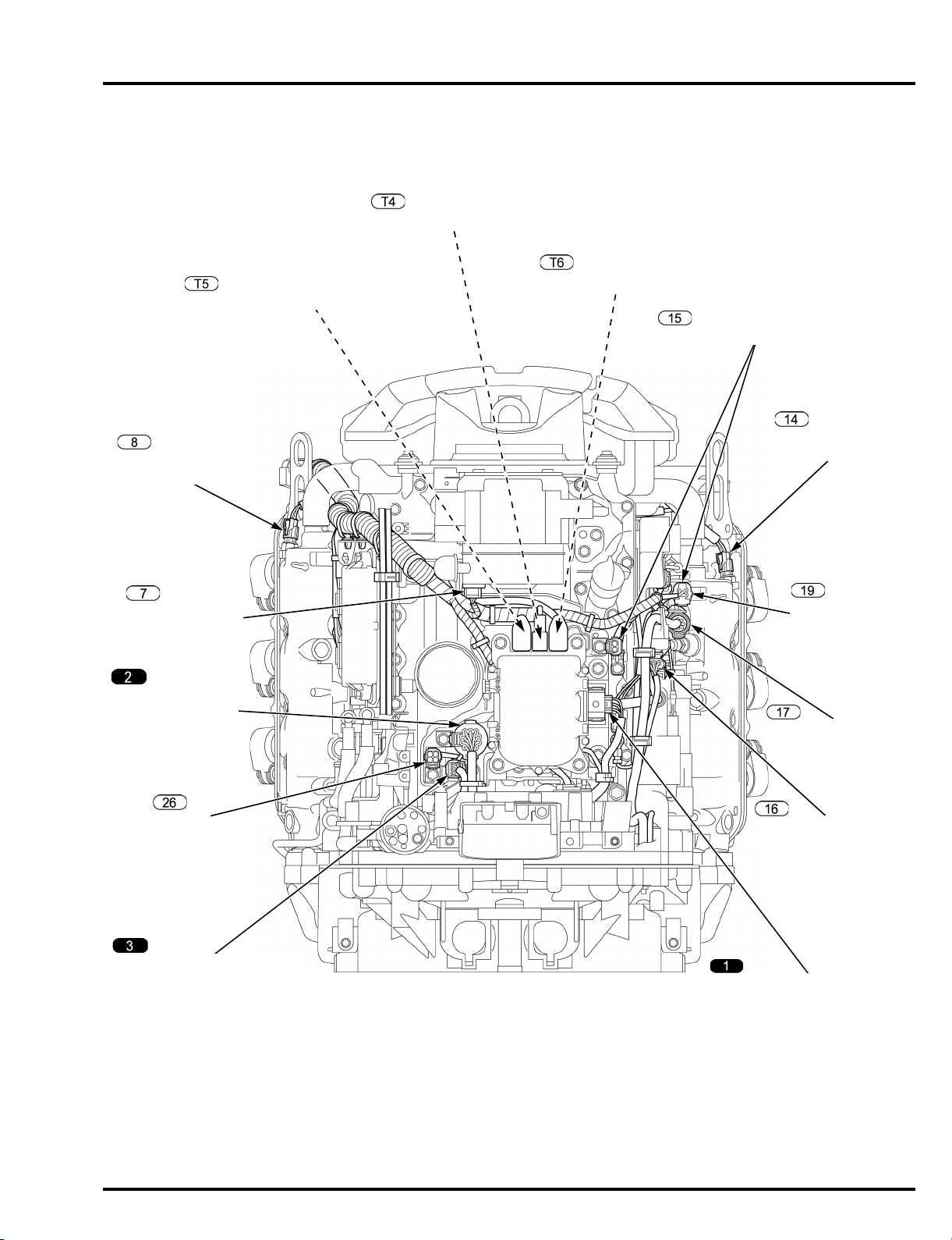
POWER TILT MOTOR
2P CONNECTOR
INTERFACE 6P CONNECTOR
INDICATOR PANEL WIRE
HARNESS 6P CONNECTOR
HO2S
4P CONNECTOR
(Except XT, XCT,
XXT, XXCT types)
SWITCH PANEL
WIRE HARNESS
14P CONNECTOR
ACG CABLE TERMINAL
POWER TILT RELAY WIRE TERMINAL
EMT SENSOR 2
2P CONNECTOR
TRIM ANGLE SENSOR
3P CONNECTOR
DLC 4P
ALTERNATOR
4P CONNECTOR
EMT SENSOR 1
2P CONNECTOR
STARTER CABLE 1 (+) TERMINAL
TACHO PULSE 2P CONNECTOR
CABLE/HARNESS ROUTING
SERVICE INFORMATION
2-3
dummyheaddummyhead
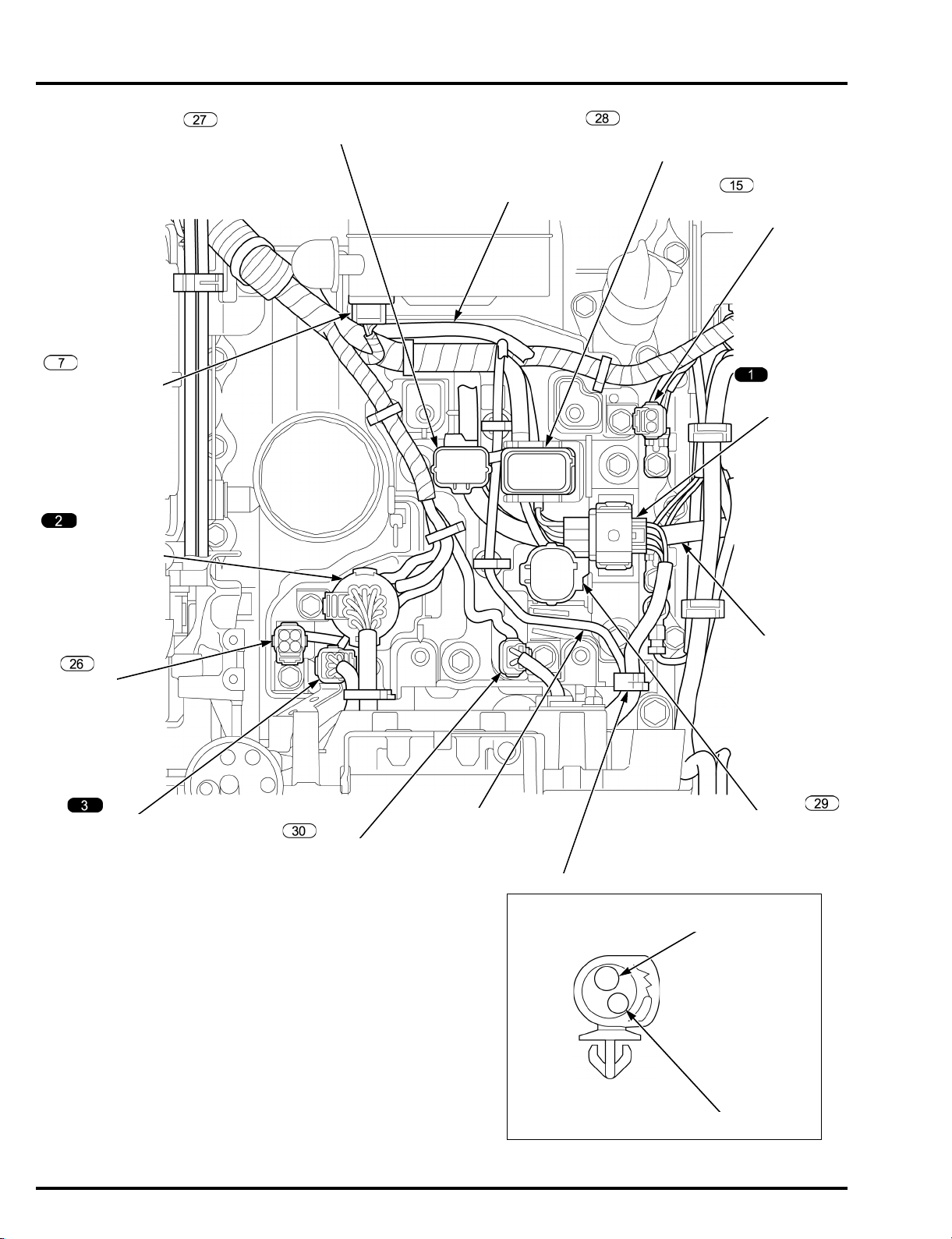
FUSE/RELAY JUNCTION BOX 8P CONNECTOR
NMEA INTERFACE WIRE
(Optional part)
POWER TILT
RELAY WIRE
TERMINAL
INTERFACE
6P CONNECTOR
ALTERNATOR
4P CONNECTOR
SWITCH PANEL
WIRE HARNESS
14P CONNECTOR
DLC 4P
INDICATOR PANEL
WIRE HARNESS
6P CONNECTOR
NEUTRAL SWITCH
2P CONNECTOR
STARTER CABLE 1 (+)
HARNESS BAND CLIP
TACHO PULSE
2P CONNECTOR
ACG CABLE
STARTER CABLE 1 (+)
FUSE/RELAY JUNCTION BOX
10P CONNECTOR
FUSE/RELAY JUNCTION BOX
23P CONNECTOR
SERVICE INFORMATION
2-4
dummyheaddummyhead
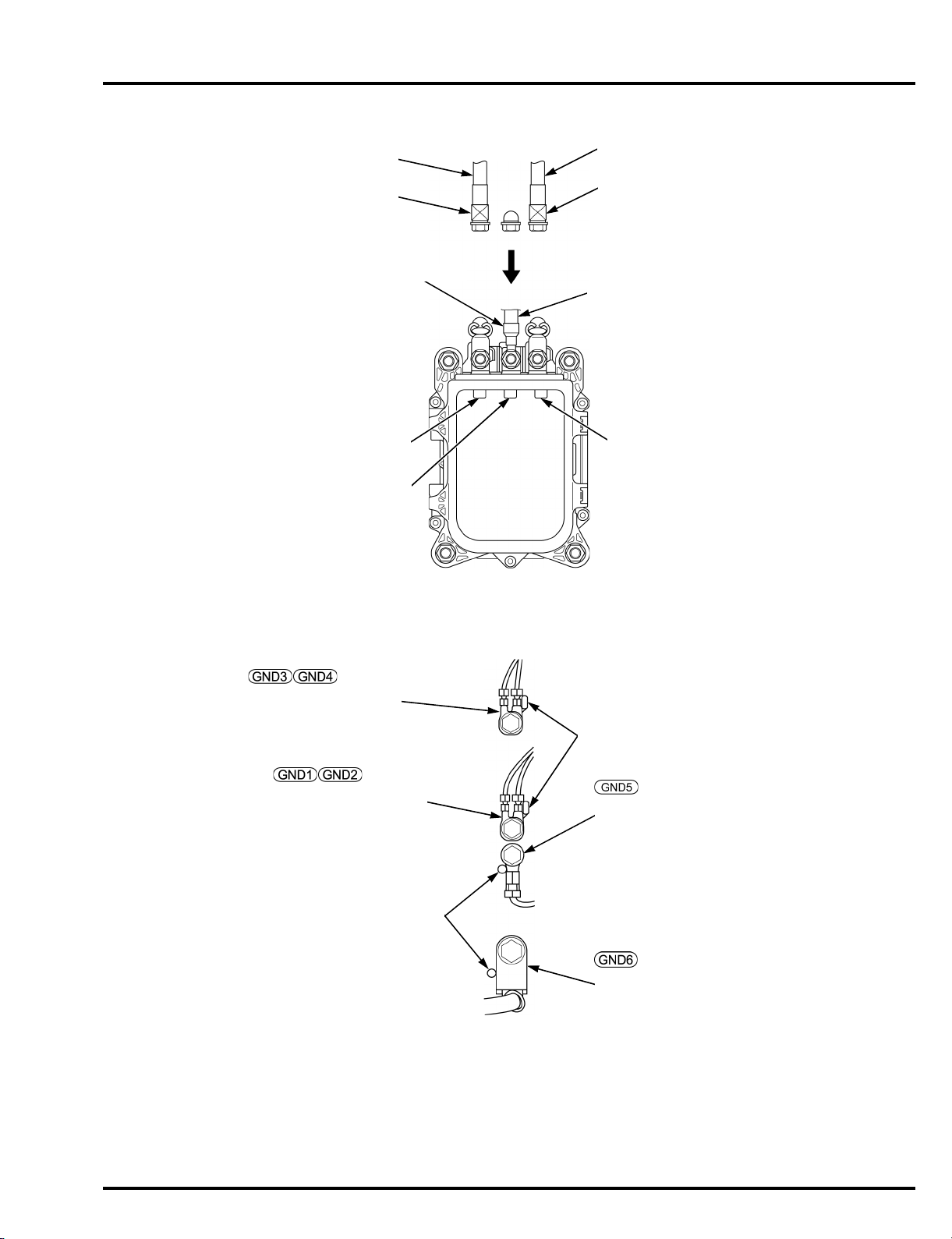
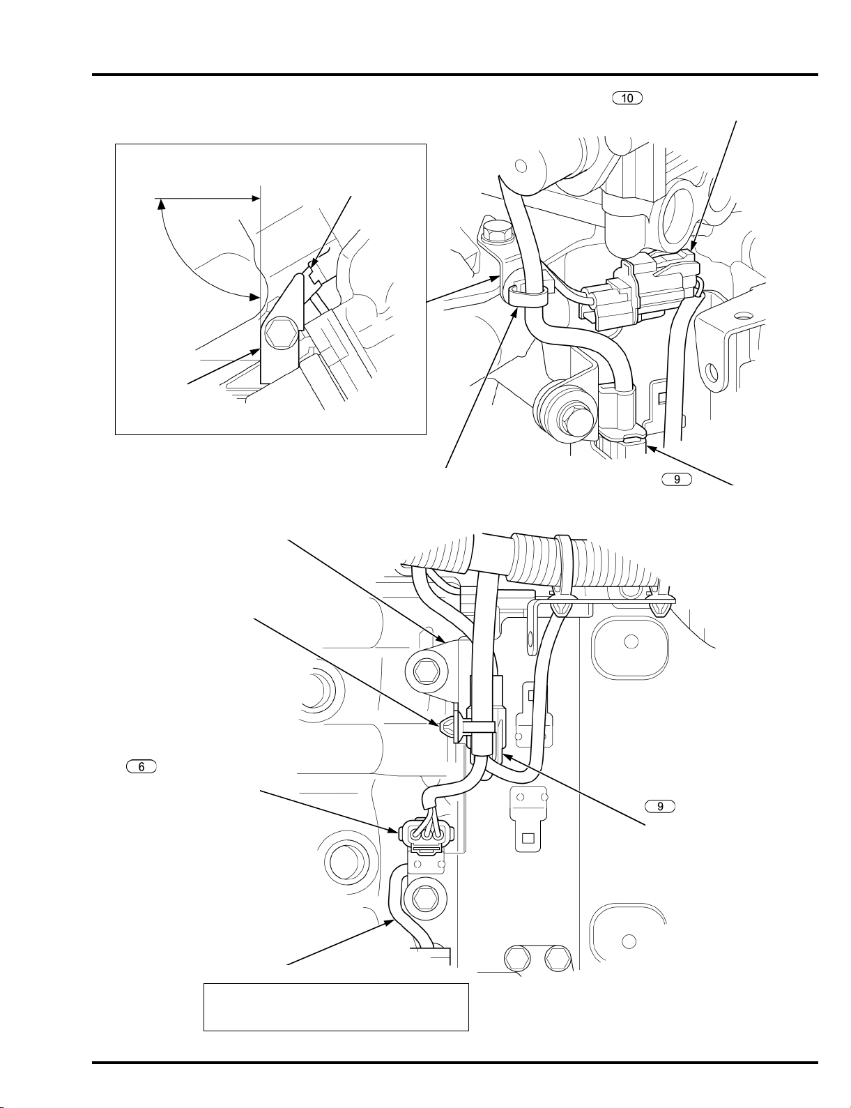
MAIN WIRE HARNESS
GROUND TERMINALS
POWER TILT RELAY CABLE
GREEN TAPE
YELLOW TAPE
GREEN
YELLOW
RED
ACG CABLE
RED TAPE
STARTER CABLE 1 (+)
MAIN WIRE HARNESS
GROUND TERMINALS
STOPPER
POWER TILT RELAY
GROUND TERMINALS
STARTER CABLE GROUND
(BATTERY GROUND TERMINAL)
STOPPER
SERVICE INFORMATION
2-5
dummyheaddummyhead
INDICATOR PANEL
WIRE HARNESS
NMEA INTERFACE WIRE
(Optional part)
STARTER CABLE (–)
SWITCH PANEL WIRE HARNESS
STARTER CABLE 1 (+)
STARTER CABLE 2 (+)
STARTER CABLE (–)
STARTER CABLE 1 (+)
NMEA INTERFACE WIRE (Optional part)
NMEA INTERFACE WIRE
(Optional part)
SWITCH PANEL
WIRE HARNESS
SHIFT CONTROL CABLE
STARTER CABLES
FUEL TUBE A
SPEEDOMETER TUBE
(Optional part)
INDICATOR PANEL
WIRE HARNESS
THROTTLE
CONTROL CABLE
NMEA INTERFACE WIRE
(Optional part)
SERVICE INFORMATION
2-6
dummyheaddummyhead
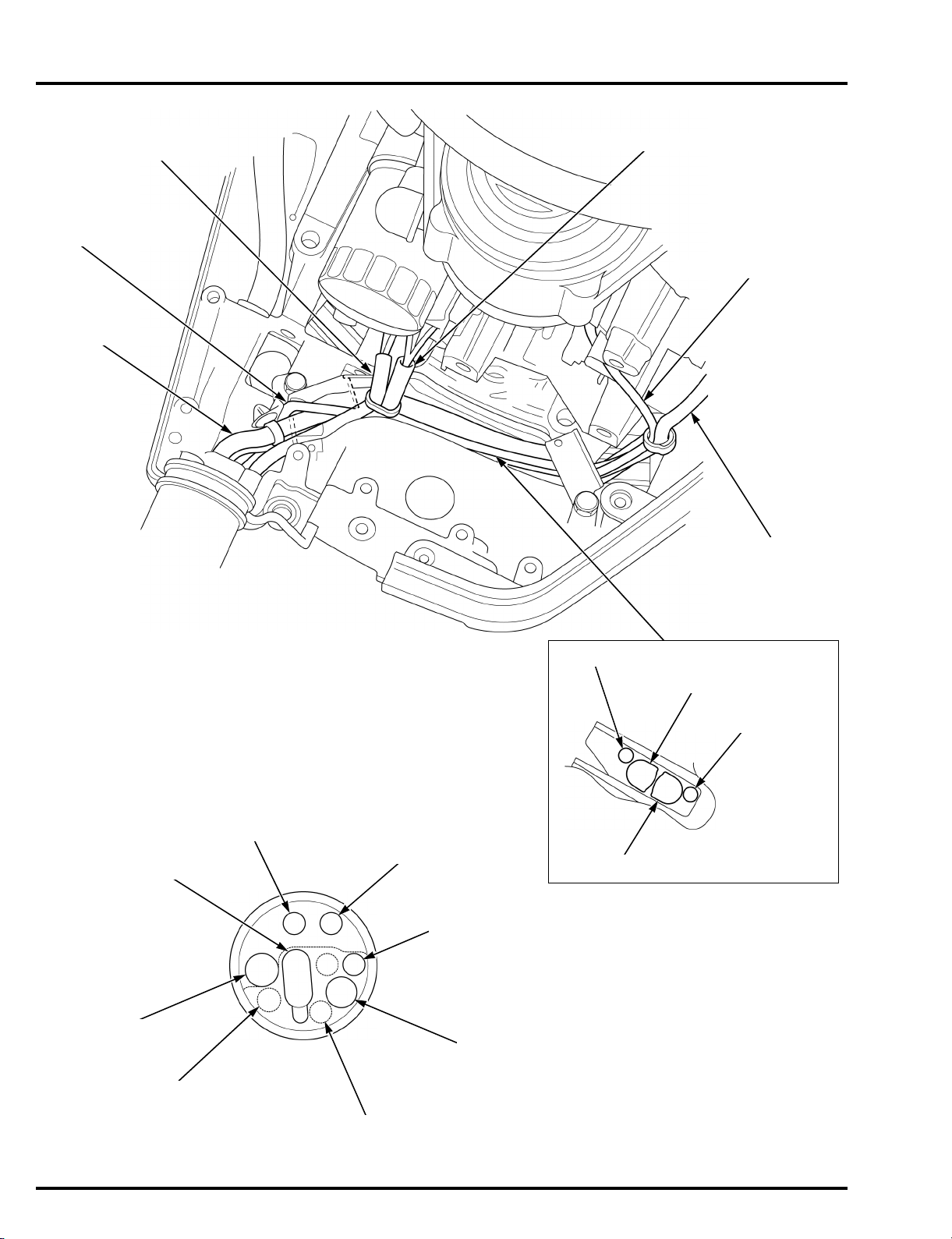
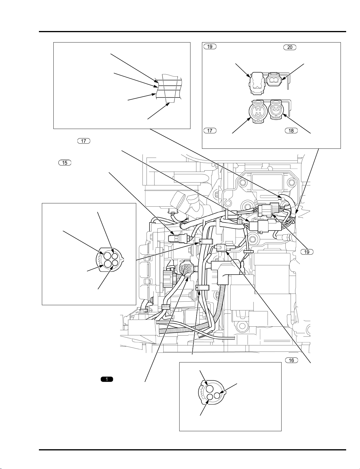
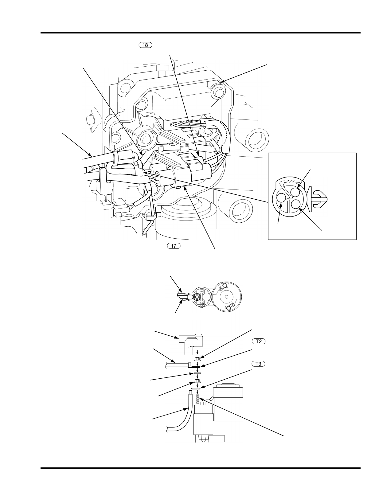
AIR FLOW CLAMP
IAC VALVE 2P CONNECTOR
Install the air flow clamp as shown.
AIR FLOW CLAMP
TP SENSOR 3P CONNECTOR
TP SENSOR
3P CONNECTOR
No.1 DIRECT
IGNITION COIL
3P CONNECTOR
No.2 DIRECT
IGNITION COIL
3P CONNECTOR
No.3 DIRECT
IGNITION COIL
3P CONNECTOR
POWER TILT SWITCH 3P CONNECTOR
THROTTLE
CABLE A
THROTTLE
CABLE B
ALTERNATOR
4P CONNECTOR
ECM 36P
CONNECTOR A (Gray)
EMT SENSOR 1 2P CONNECTOR
MAIN WIRE HARNESS
ECM 36P CONNECTOR B (Black)
SERVICE INFORMATION
2-7
dummyheaddummyhead
Install the joint connector 1 as shown.
After installation, check the main wire
harness for twist.
ACG CABLE TERMINAL
STARTER CABLE 1 (+) TERMINAL
POWER TILT RELAY WIRE TERMINAL
IAC VALVE 2P CONNECTOR
TP SENSOR 3P CONNECTOR
JOINT CONNECTOR 1
COVER
ALTERNATOR B TERMINAL
COVER
SERVICE INFORMATION
2-8
dummyheaddummyhead
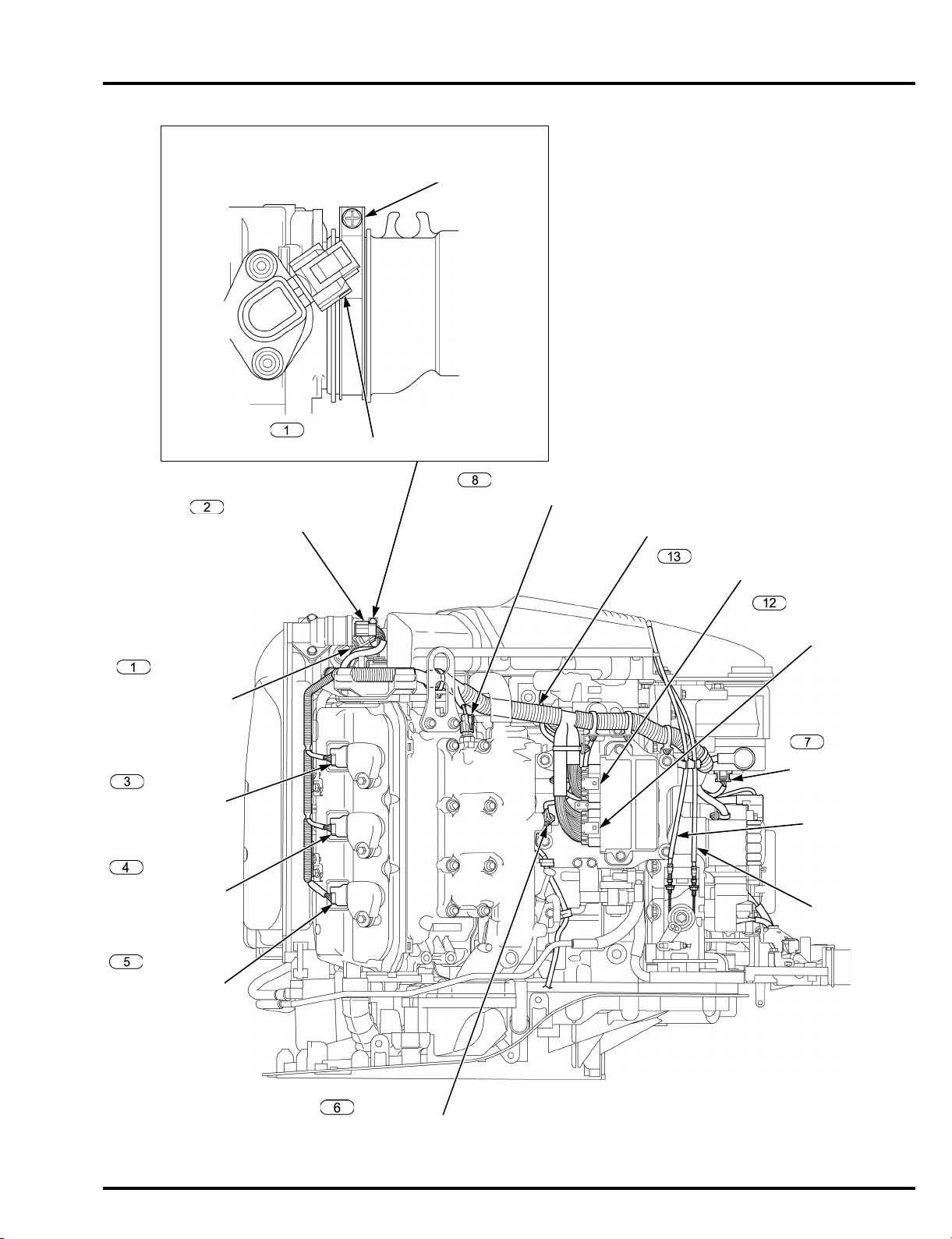
VTEC SOLENOID VALVE
1P CONNECTOR
(BF225 only)
HARNESS BAND CLIP
Install the power tilt switch wire from the outside
of the ECM bracket and check that the wire do
not interfere with the ECM bracket.
CKP SENSOR 2P CONNECTOR
ECM BRACKET
HARNESS BAND CLIP
POWER TILT SWITCH
3P CONNECTOR
POWER TILT SWITCH WIRE
VTEC SOLENOID VALVE
1P CONNECTOR
(BF225 only)
Align the stay with the center of grommet.
Cruising direction
GROMMET
90°
STAY
SERVICE INFORMATION
2-9
dummyheaddummyhead
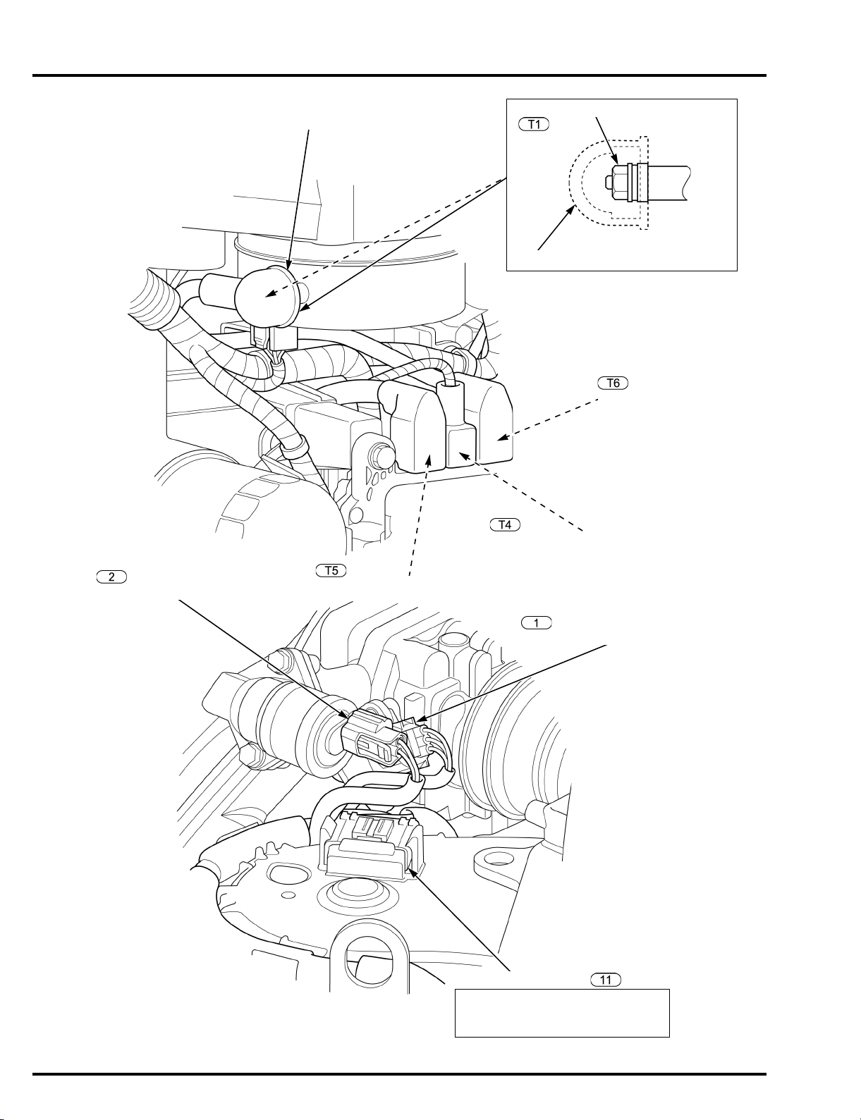
EMT SENSOR 2
2P CONNECTOR
No.4 DIRECT IGNITION COIL
3P CONNECTOR
No.5 DIRECT IGNITION COIL
3P CONNECTOR
No.6 DIRECT IGNITION COIL
3P CONNECTOR
WATER LEVEL SENSOR 2P CONNECTOR
IAT SENSOR 2P CONNECTOR
MAP SENSOR
3P CONNECTOR
HARNESS BAND CLIP
SERVICE INFORMATION
2-10
dummyheaddummyhead
WIRE HARNESS CLIP
POWER TILT MOTOR 2P CONNECTOR
TACHO PULSE 2P CONNECTOR
TRIM ANGLE SENSOR
3P CONNECTOR
INTERFACE 6P CONNECTOR
POWER TILT MOTOR WIRE
POWER TILT RELAY
GROUND TERMINALS CABLE
TRIM ANGLE
SENSOR WIRE
POWER TILT RELAY CABLE
POWER TILT
MOTOR WIRE
POWER TILT RELAY
GROUND TERMINALS CABLE
WIRE HARNESS CLIP
HO2S 4P CONNECTOR
(Except XT, XCT, XXT,
XXCT types)
POWER TILT RELAY
2P CONNECTOR
POWER TILT RELAY
1P CONNECTOR
POWER TILT MOTOR
2P CONNECTOR
POWER TILT MOTOR 2P CONNECTOR WIRE
POWER TILT RELAY CASE
POWER TILT MOTOR
2P CONNECTOR/
POWER TILT RELAY
1P CONNECTOR WIRE
POWER TILT RELAY
GROUND TERMINALS
CABLE
MAIN WIRE
HARNESS
GROUND CABLE
HO2S 4P
CONNECTOR
(Except XT, XCT,
XXT, XXCT types)
SERVICE INFORMATION
2-11
dummyheaddummyhead
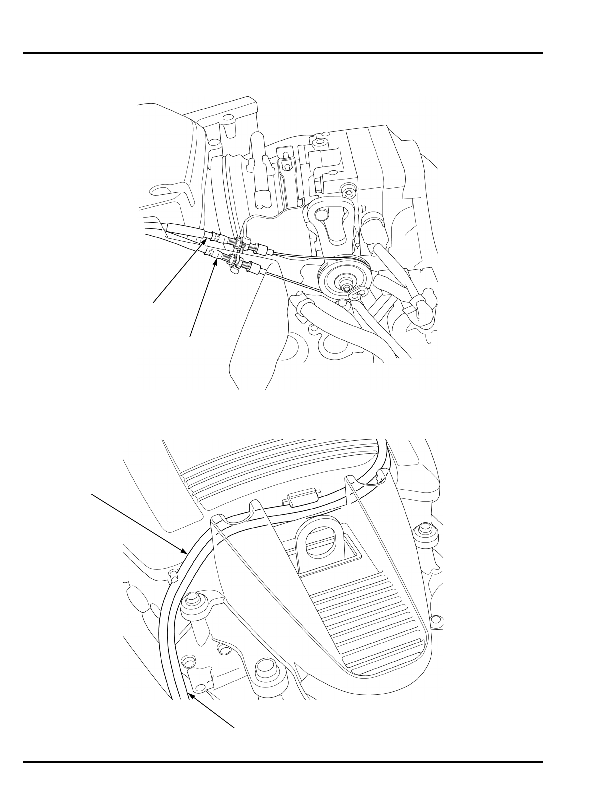
THROTTLE CABLE B
THROTTLE CABLE A
THROTTLE CABLE B
THROTTLE CABLE A
SERVICE INFORMATION
2-12
dummyheaddummyhead
WIRE HARNESS CLIP
POWER TILT RELAY
POWER TILT RELAY
GROUND TERMINALS CABLE
POWER TILT RELAY 1P CONNECTOR
POWER TILT MOTOR 2P CONNECTOR
STARTER CABLE 2 (+)
POWER TILT RELAY CABLE
STARTER TERMINAL COVER
POWER TILT RELAY CABLE
WASHER (8 mm)
STARTER CABLE 2 (+)
STARTER MOTOR B
TERMINAL NUT (8 mm)
STARTER MOTOR B TERMINAL
STARTER MOTOR B TERMINAL NUT (8 mm)
MAIN WIRE
HARNESS
POWER TILT
RELAY CABLE
POWER TILT RELAY GROUND
TERMINALS CABLE
MAIN WIRE
HARNESS
STARTER CABLE 2 (+) TERMINAL
POWER TILT RELAY CABLE TERMINAL
SERVICE INFORMATION
2-13
dummyheaddummyhead
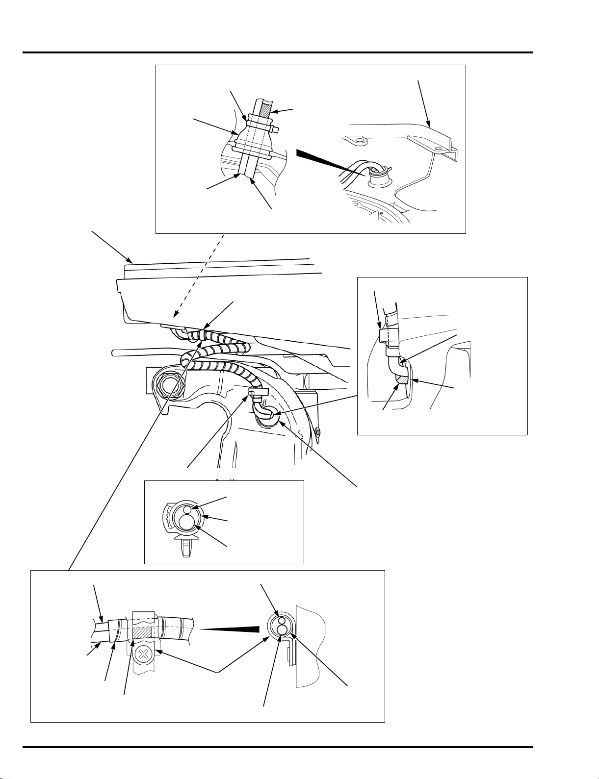
L. ENGINE UNDER COVER
CLIP
MOTOR CORD BUSHING
TRIM ANGLE
SENSOR WIRE
SPIRAL TUBE
POWER TILT
MOTOR WIRE
WIRE HARNESS CLIP
TRIM ANGLE
SENSOR WIRE
MOTOR CORD
BUSHING
Align the tape end with the
motor cord bushing end.
WIRE HARNESS CLIP
WIRE BAND (Cut off the surplus band
remaining it about 5 mm (0.2 in))
UNDER CASE
GROMMET
TRIM ANGLE
SENSOR WIRE
POWER TILT MOTOR WIRE
Align the white tape end with
the under case grommet end.
L. ENGINE UNDER COVER
TRIM ANGLE SENSOR WIRE
POWER TILT
MOTOR WIRE
SPIRAL TUBE
Align the tape end of the power trim/tilt motor wire
with the clip end.
POWER TILT MOTOR WIRE
SPIRAL TUBE
TRIM ANGLE SENSOR WIRE
CLIP
SERVICE INFORMATION
2-14
dummyheaddummyhead
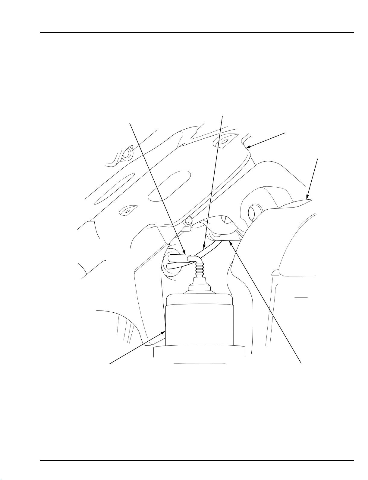
SWIVEL CASE
R. STERN BRACKET
TRIM ANGLE SENSOR
POWER TILT MOTOR
POWER TILT MOTOR WIRE
Check the wire for twist.
TRIM ANGLE SENSOR WIRE
Check the wire for slack.
SERVICE INFORMATION
2-15
dummyheaddummyhead
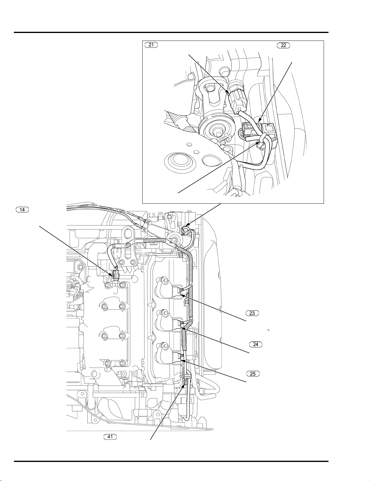
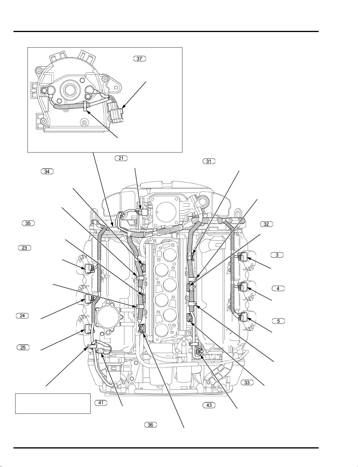
L. TIMING BELT BACK COVER
Align the band end of the water
level sensor wire (sensor side)
with the harness clip end.
No.1 FUEL INJECTOR 2P CONNECTOR
WIRE HARNESS CLIP
No.2 FUEL INJECTOR
2P CONNECTOR
No.1 DIRECT
IGNITION COIL
3P CONNECTOR
No.2 DIRECT
IGNITION COIL
3P CONNECTOR
No.3 DIRECT
IGNITION COIL
3P CONNECTOR
WIRE HARNESS CLIP
No.3 FUEL INJECTOR
2P CONNECTOR
FUEL PUMP (HIGH PRESSURE SIDE)
2P CONNECTOR
No.6 FUEL INJECTOR 2P CONNECTOR
WATER LEVEL SENSOR
2P CONNECTOR
HARNESS BAND CLIP
No.6 DIRECT
IGNITION COIL
3P CONNECTOR
No.5 DIRECT
IGNITION COIL
3P CONNECTOR
No.4 DIRECT
IGNITION COIL
3P CONNECTOR
WIRE HARNESS CLIP
No.5 FUEL INJECTOR
2P CONNECTOR
WIRE HARNESS CLIP
No.4 FUEL INJECTOR
2P CONNECTOR
IAT SENSOR 2P CONNECTOR
CMP SENSOR 1
CMP SENSOR 2
4P CONNECTOR
HARNESS BAND CLIP (Cut off the surplus
band remaining it about 10 mm (0.4 in))
SERVICE INFORMATION
2-16
 Loading...