

Tohatsu 5BS 04-93, 5 B, 5B 04-93, 5 BS User Manual
OWNER’S WAND E3:,00&
FOREWORD
Thank you for choosing a TOHATSU OUTBOARD MOTOR.
This manual describes its workings and its main features. Before using
the motor study these instructions and get to know what a fine engine
it is. Like any other piece of machinery it requires careful and knowledgeable attenlion, and in return it will give you excellent service over
the years. Our policy is one of continuous product improvement so we
reserve the right to incorporate changes without prior notice.
TOHATSU CORPORATION
v
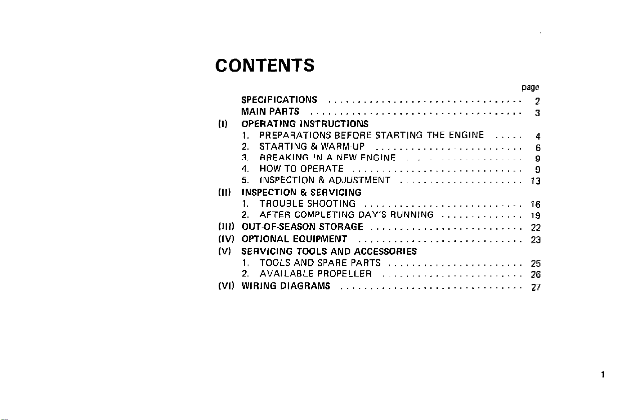
CONTENTS
SPECIFICATIONS .
MAINPARTS . .._...........................
(1) OPERATING INSTRUCTIONS
1. PREPARATIONS BEFORE STARTING THE ENGINE
2. STARTING 81 WARM-UP ~.
3. BREAKING IN A NEW ENGINE
4. HOWTOOPERATE .,..,.,._,.,_......,.,...
5. INSPECTION & ADJUSTMENT
(II) INSPECTION 5 SEAVICING
1. TROUBLESHOOTING ..,........,....,.,....
2. AFTER COMPLETING DAY’S RUNNING
(Ill) OUT-OF-SEASON STORAGE
III/I OPTIONAL EQUIPMENT .
(VI SERVICING TOOLS AND ACCESSORIES
1. TOOLS AND SPARE PARTS
2. AVAILABLE PROPELLER .~..,,..,......,....
(VI) WIRING DIAGRAMS _. _.
1
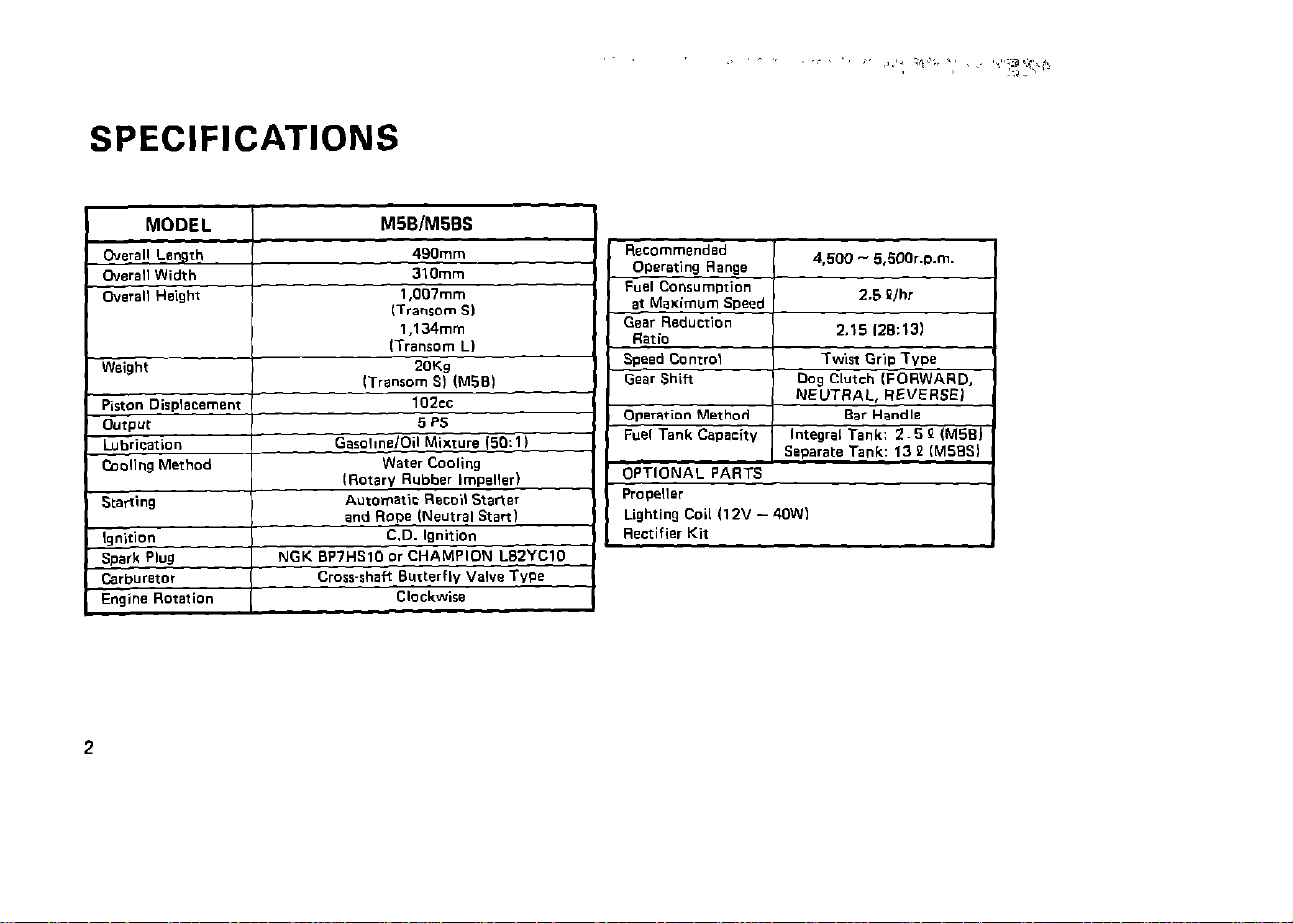
SPECIFICATIONS
Recommended
operating Range
Fuel Conr”mDrion
at Marimum Speed
Gear Reducrion
a-*;..
OPTlONAL PARTS
Propeller
Lighting Coil (12” - 4OWI
Rectifier Kit
4.500 - 5,5Wr.!%rn.
2.5 P/h,
2.15 12&131
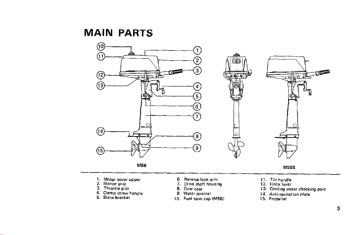
MAIN PARTS
( I) OPERATING INSTRUCTIONS
1. PREPARATIONS BEFORE STARTING
THE ENGINE
Gasoline with 86 OCTANE (A.K.I.) or over is recommended for easy starting and long life.
(1) Fuel
1) Check that there is sufficient fuel for the day’s
operation. Carry additional fuel for use in an
emergency and check it before running. Running
out of fuel can cause both inconvenience and
serious injury.
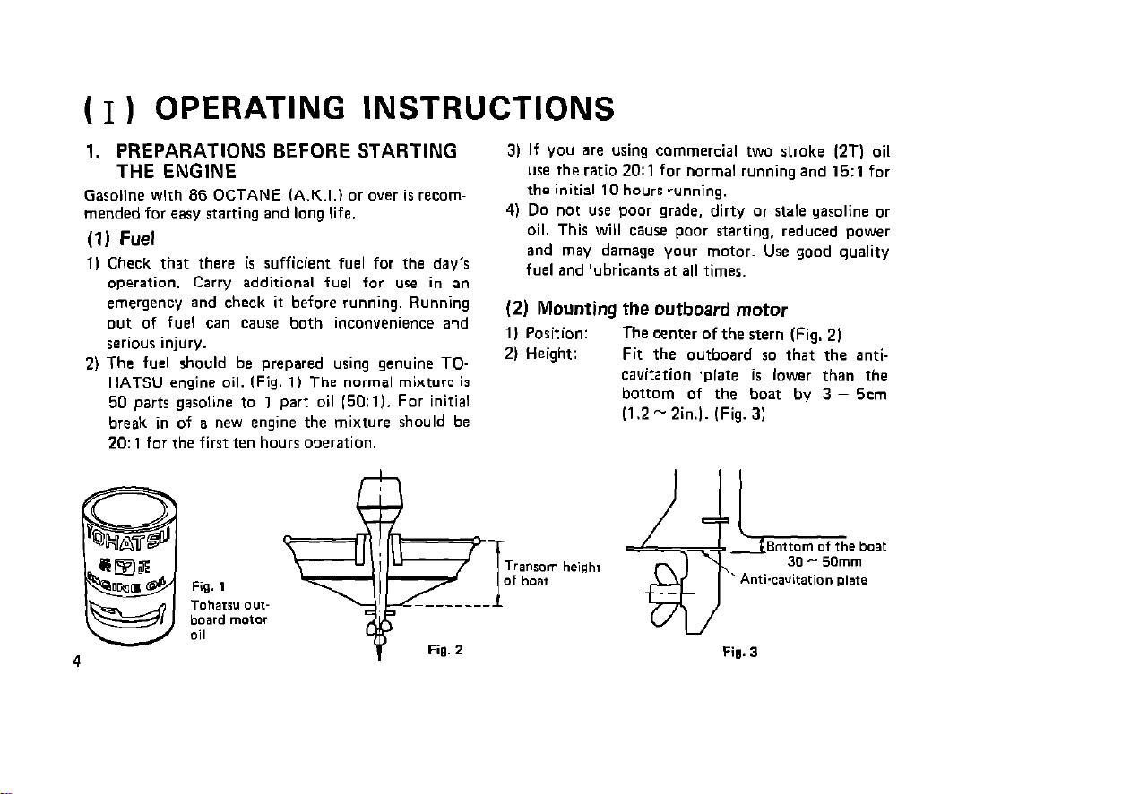
2) The fuel should be prepared using genuine TOHATSU engine oil. (Fig. 11 The normal mixture is
50 parts gasoline to 1 part oil 150:~). For initial
break in of a new engine the mixture should be
20: 1 for the first ten hours operation.
3) If you are using commercial two stroke (2T) oil
use the ratio 2O:l for normal running and 15:l for
the initial 10 hours running.
4) Do not use poor grade, dirty or stale gasoline or
oil. This will cause poor starting, reduced power
and may damage your motor. Use good quality
fuel and lubricants at all times.
(2) Mounting the outboard motor
11 Position:
2) Height:
The center of the stern (Fig. 21
Fit the outboard so that the anti-
cavitation ‘plate is lower than the
bottom of the boat by 3 - 5cm
11.2-2in.l. (Fig. 3)
Anti-cavitation plate
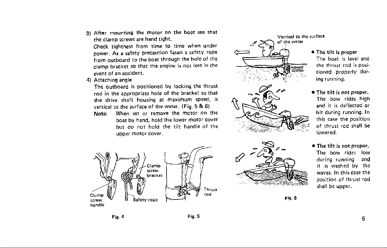
3) After mounting the motor on the boat see that
the clamp screws are hand tight.
Check tightness from time to time when under
power. As a safety precaution fasen a safetv rope
from outboard to the boat through the hole of the
clamp bracket so that the engine is not lost in the
event of an accident.
4) Attaching angle
The outboard is positioned by locking the thrust
rod in the appropriate hole of the bracket so that
the drive shaft housing at maximum speed, is
vertical to the surface of the water. (Fig, 5 & 6)
Note: When set or remove the motor on the
boat by hand. hold the lower motor cover
but do not hold the tilt handle of the
upper motor cover.
. The tilt is proper
The boat is level and
the thrust rod is positioned properly during running.
l The tilt is not proper.
The bow rides high
and it is deflected or
hit during running. In
this case the position
of Thrust rod shall be
lowered.
T3
d,
l The tilt is not proper.
The bow rides low
during running and
it is washed by the
waves. In this case the
position of thrust rod
shall be upper.
5
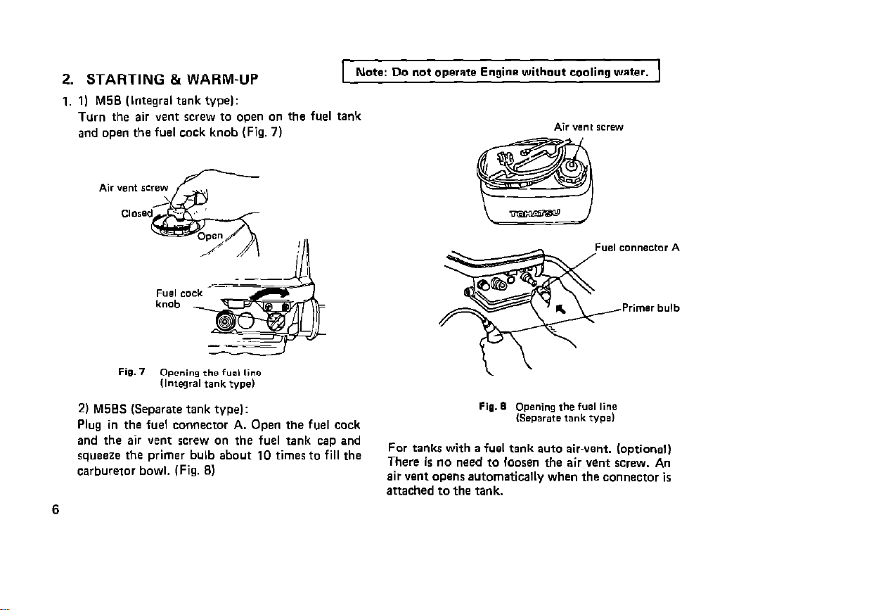
2. STARTING &WARM-UP
1. 1) M5B (Integral tank type):
Turn the air vent screw to open on the fuel tank
and open the fuel cock knob (Fig. 7)
2) M50S (Separate tank type):
Plug in the fuel connector A. Open the fuel cock
and the air vent screw on the fuel tank cap and
squeeze the primer bulb about 10 times to fill the
carburetor bowl. (Fig. 81
6
Note: Do not operate Engine without cooling water.
For tanks with a fuel tank auto air-vent. (optional)
There is no need to loosen the air vent screw. An
air vent opens automatically when the connector is
attached to the tank.
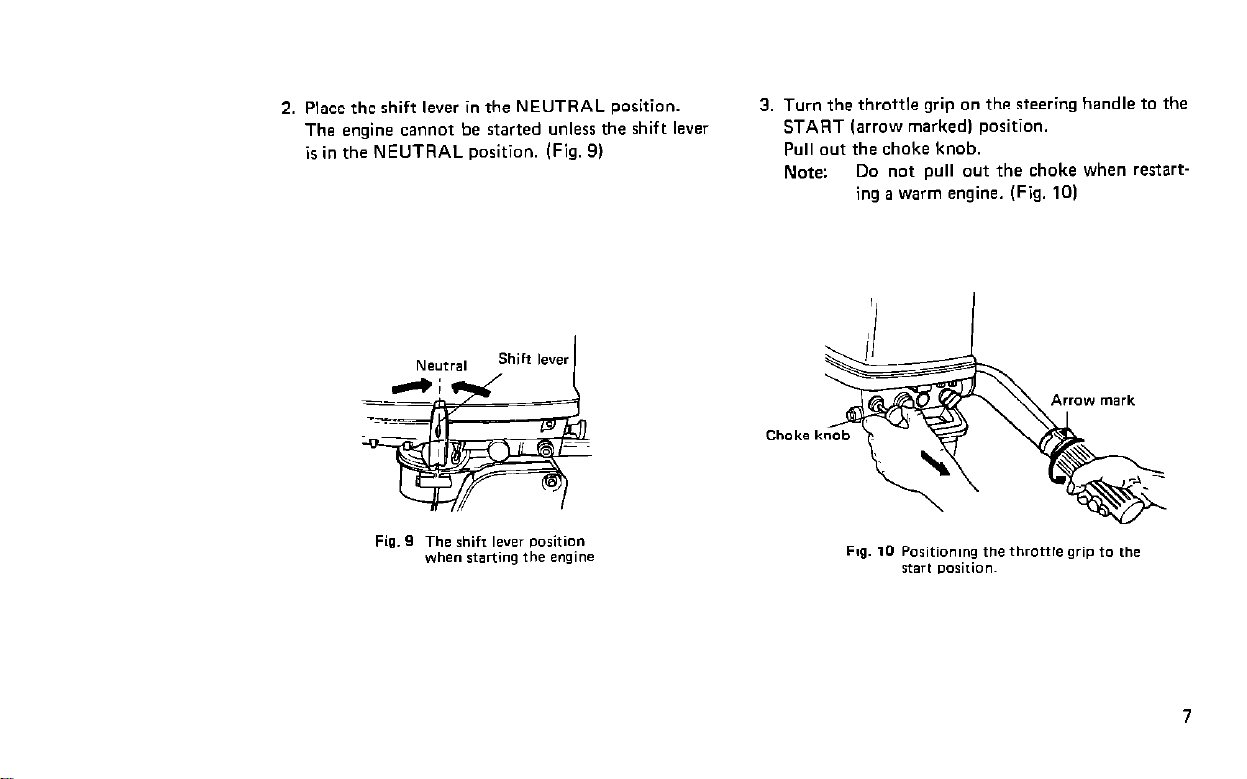
2. Place the shift lever in the NEUTRAL position.
The engine cannot be started unless the shift lever
is in the NEUTRAL position. (Fig. 9)
3. Turn the throttle grip on the steering handle to the
START (arrow marked) position.
Pull out the choke knob.
Note:
Do not pull out the choke when restarting a warm engine. (Fig. 10)
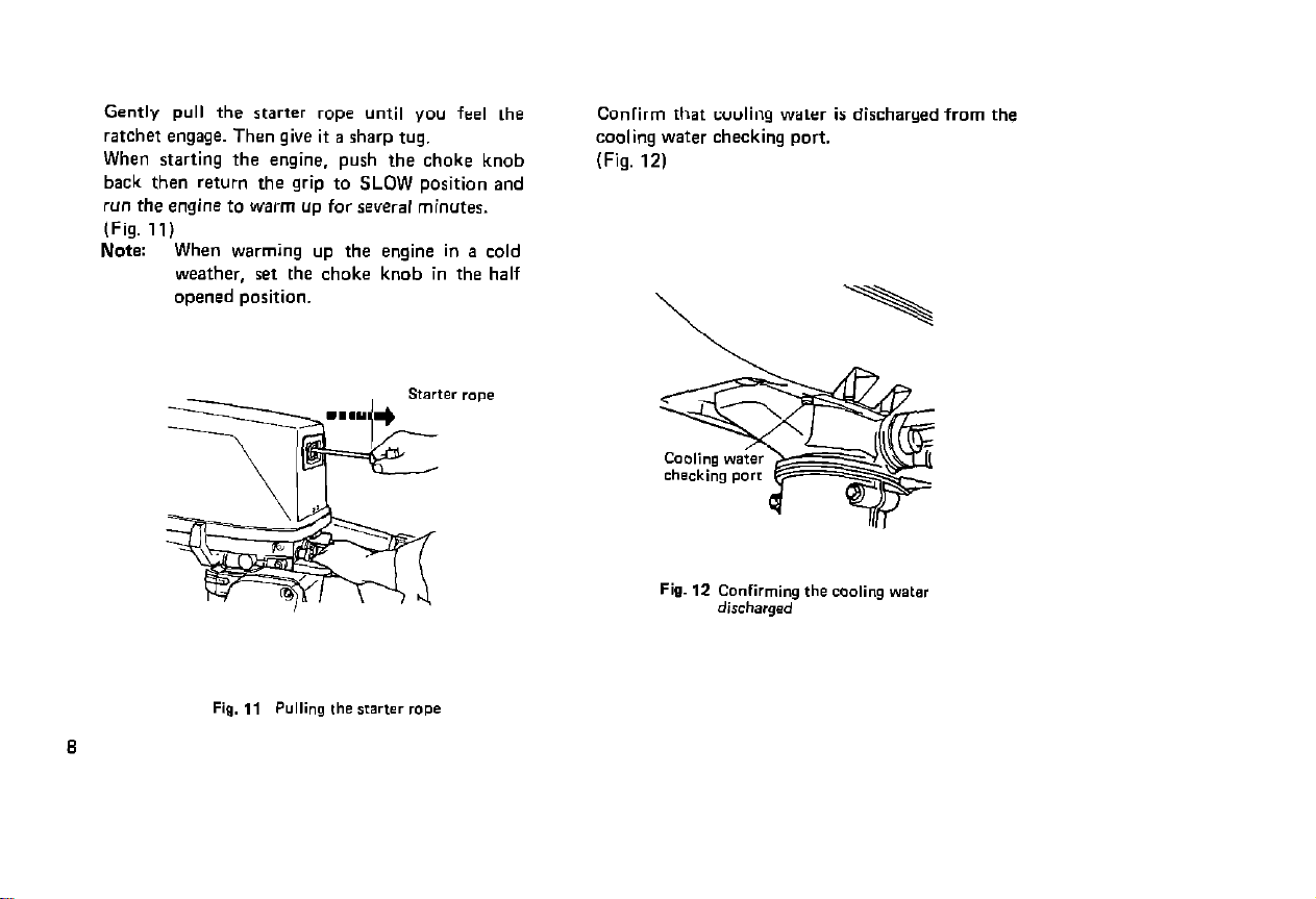
Gently pull the starter rope until you feel the
ratchet engage. Then give it a sharp tug.
When starting the engine. push the choke knob
back then return the grip to SLOW position and
run the engine to warm up for sever.4 minutes.
(Fig. 11)
Note: When warming up the engine in a cold
weather, set the choke knob in the half
opened position.
Confirm that cooling water is discharged from the
cooling water checking port.
(Fig. 12)
\
 Loading...