

TOHATSU 40c Owner's Handbook Manual

:I:,:
:.,,.,
;((c::{
:: :
::::.:::: :,..:..
..,
ii/: .:
,..,..
;’
OWNER’S HAND B,;,OOs

Copyright © 2007 Tohatsu Corporation. All rights reserved. No part
of this manual may be reproduced or transmitted in any form or by
any means without the express written permission of Tohatsu
Corporation.

FOREWORD
To get the maximum amount of pleasure and performance out of an
outboard motor it IS important that you understand the functions of
the mechanism and learn to operate the controls with ease and
confidence. This operatmg manual will explain the construction of the
TOHATSU outboard motor and how to carry out periodical inspection.
As TOHATSU follows a policy of continuous product improvement, it
reserves the right to make changes to specifications without prior
notice. For further informatmn please contact TOHATSU dealers or
TOHATSU distributors.
TOHAT5Ll CORPORATION
v
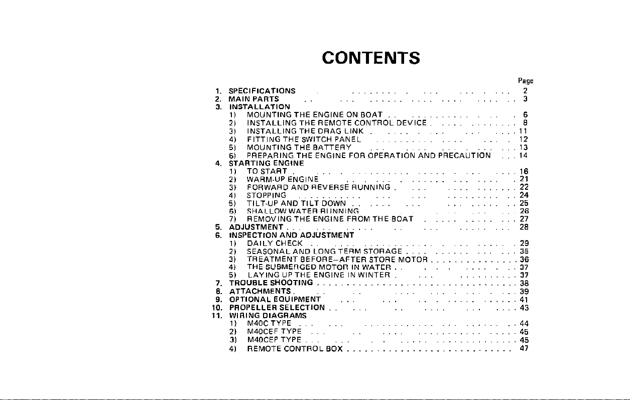
CONTENTS
Page
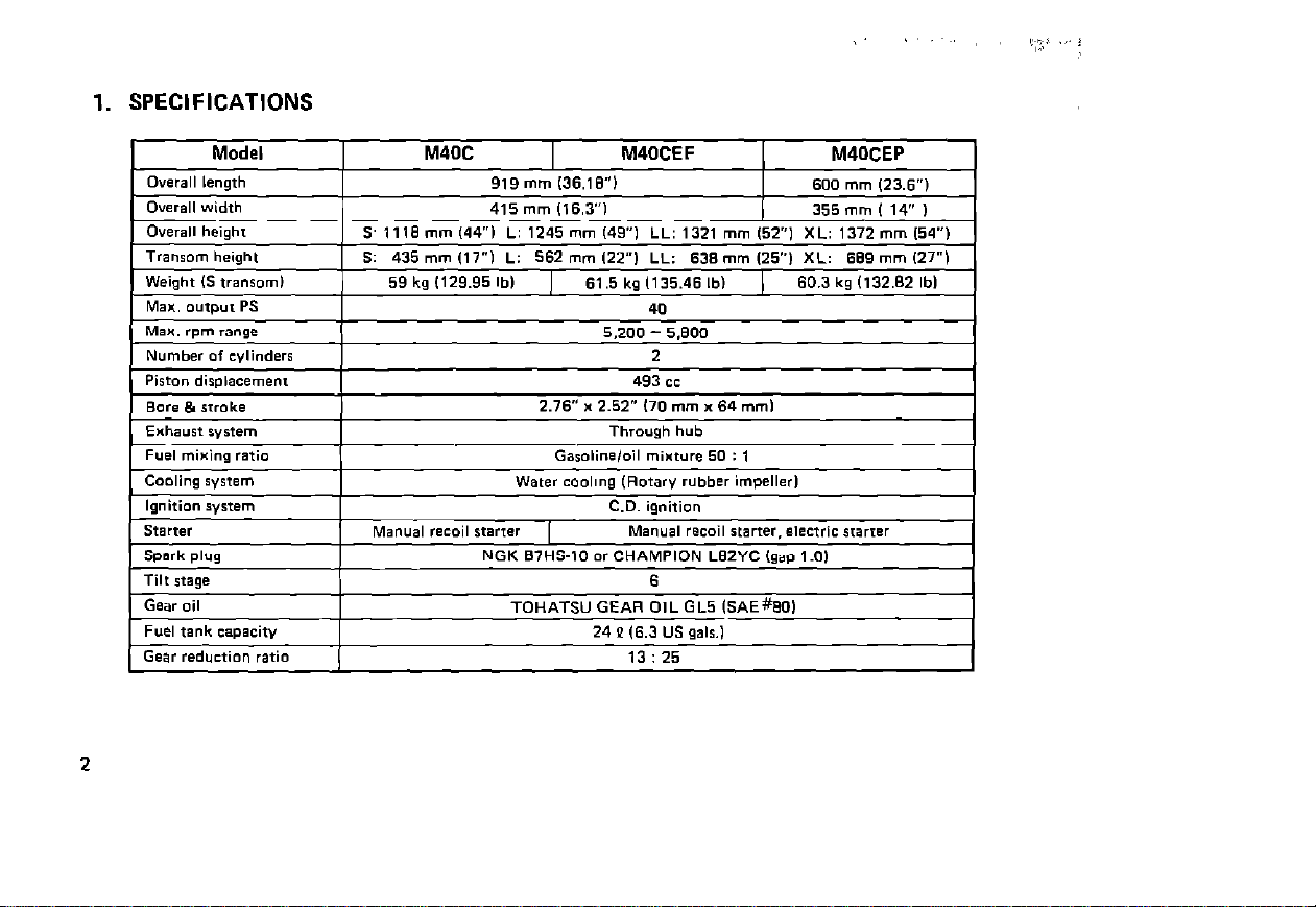
1. SPECIFICATIONS
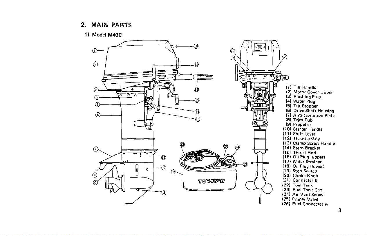
2. MAIN PARTS
1) Model M40C
/
0
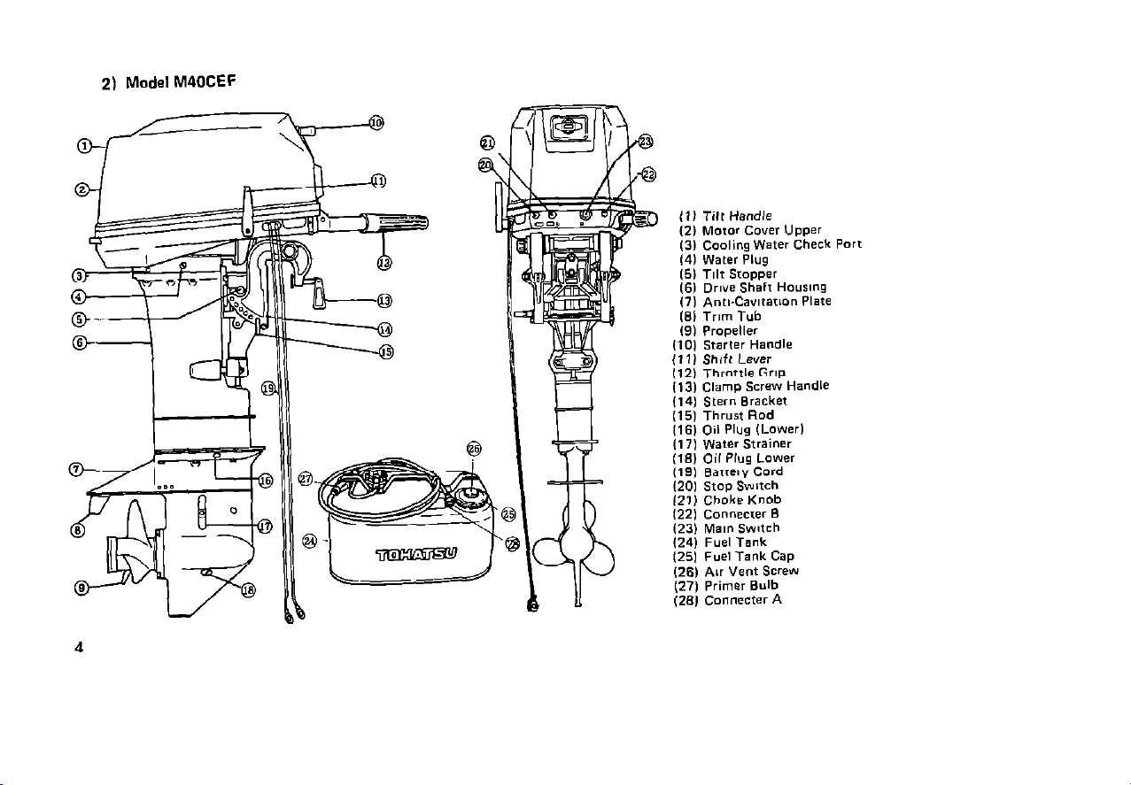
2)
Model M40CEF
t
-4
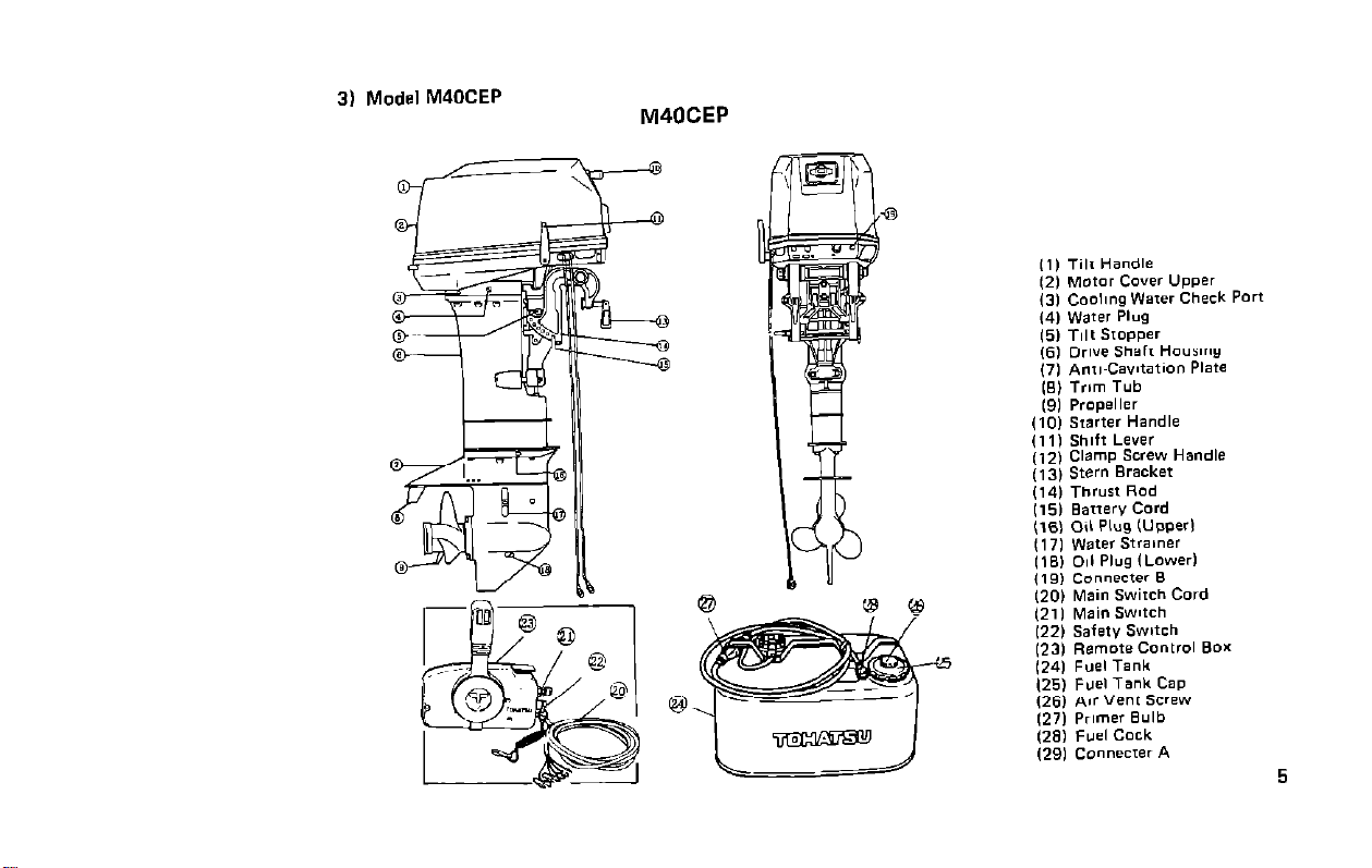
3) Model M40CEP
M40CEP
3. INSTALLATION
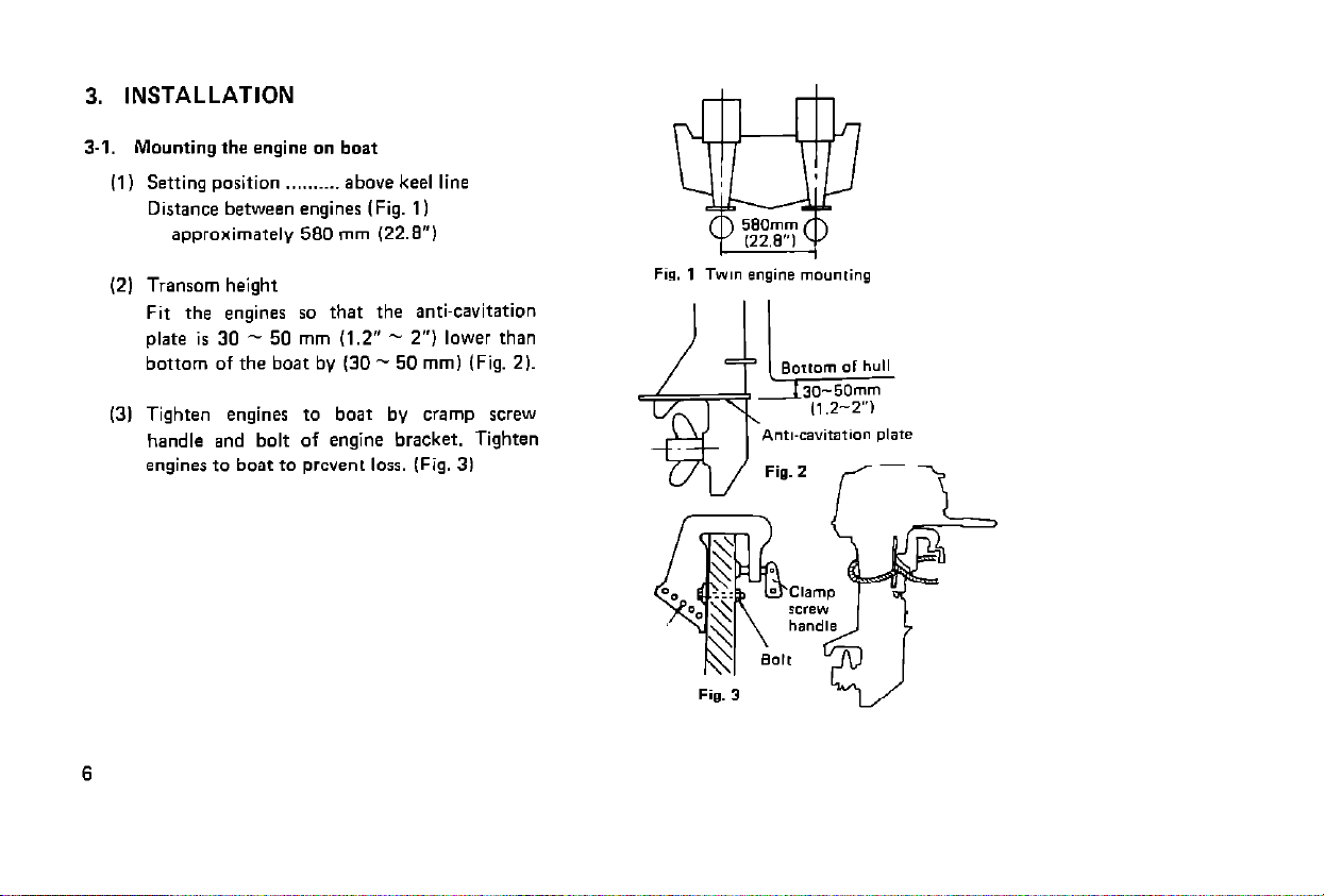
3-I. Mounting the engine on boat
(1) Setting position ..,......_ above keel line
Distance between engines (Fig. 1 I
approximately 580 mm V2.8”1
(2) Transom height
Fit the engines so that the anti-cavitation
plate is 30 - 50 mm (1.2” - 2”) lower than
bottom of the boat by (30 - 50 mm1 (Fig. 21.
(3) Tighten engines to boat by cramp screw
handle and bolt of engine bracket. Tighten
engines to boat to prevent loss. (Fig. 31
Fisl. 1 Twm engine mounting
Ant,-cavitation plate
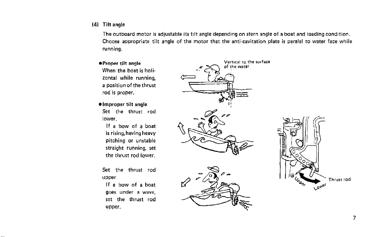
(4) Tilt angle
The outboard motor is adjustable its tilt angle depending on stern angle of a boat and loading condition.
Choose appropriate tilt angle of the motor that the anti-cavitation plate is paralel to water face while
running.
aProper tilt angle
When the boat is holizontal while running,
a position of the thrust
rod is proper.
l
improper tilt angle
Set the thrust rod
lower.
If a bow of a boat
is rising,having heavy
pitching or unstable
straight running, ret
the thrust rod lower.
Set the thrust rod
UPPer
If a bow of a boat
goes under a wave,
set the thrust rod
upper.
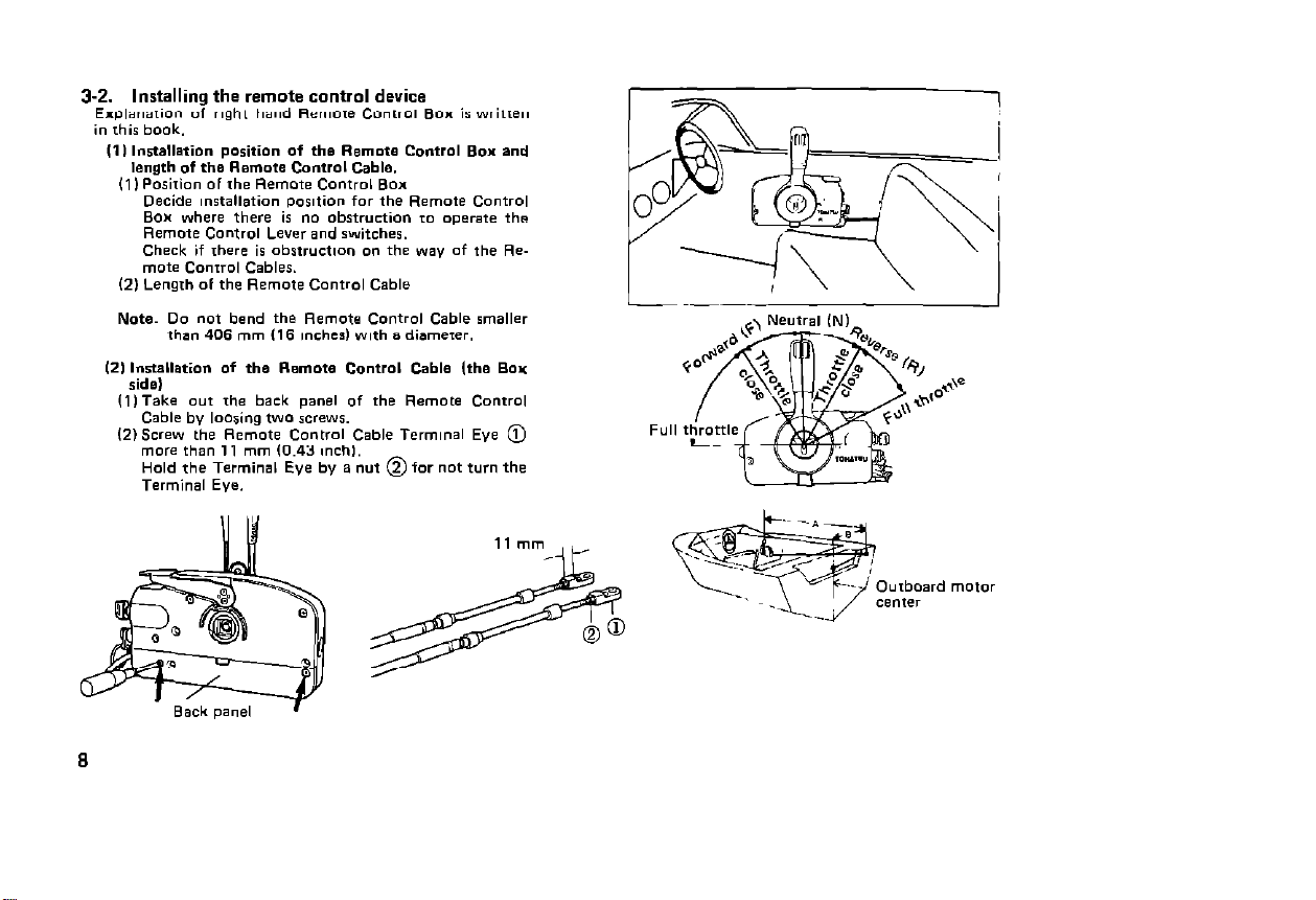
3-2. Installing the remote control device
Erplanarion of rlght hand Remme Conrro, BOX is written
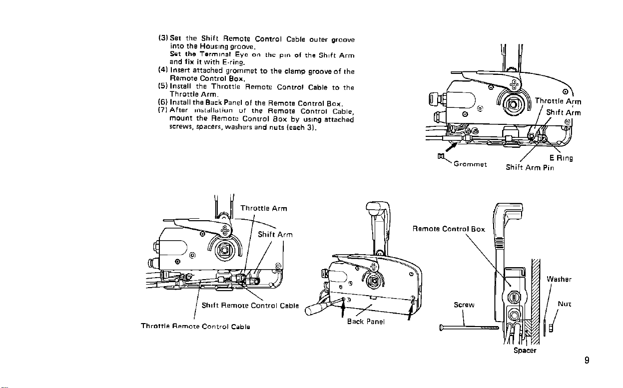
Shift Remme
I
Throttle Remore Control Cable
Cable
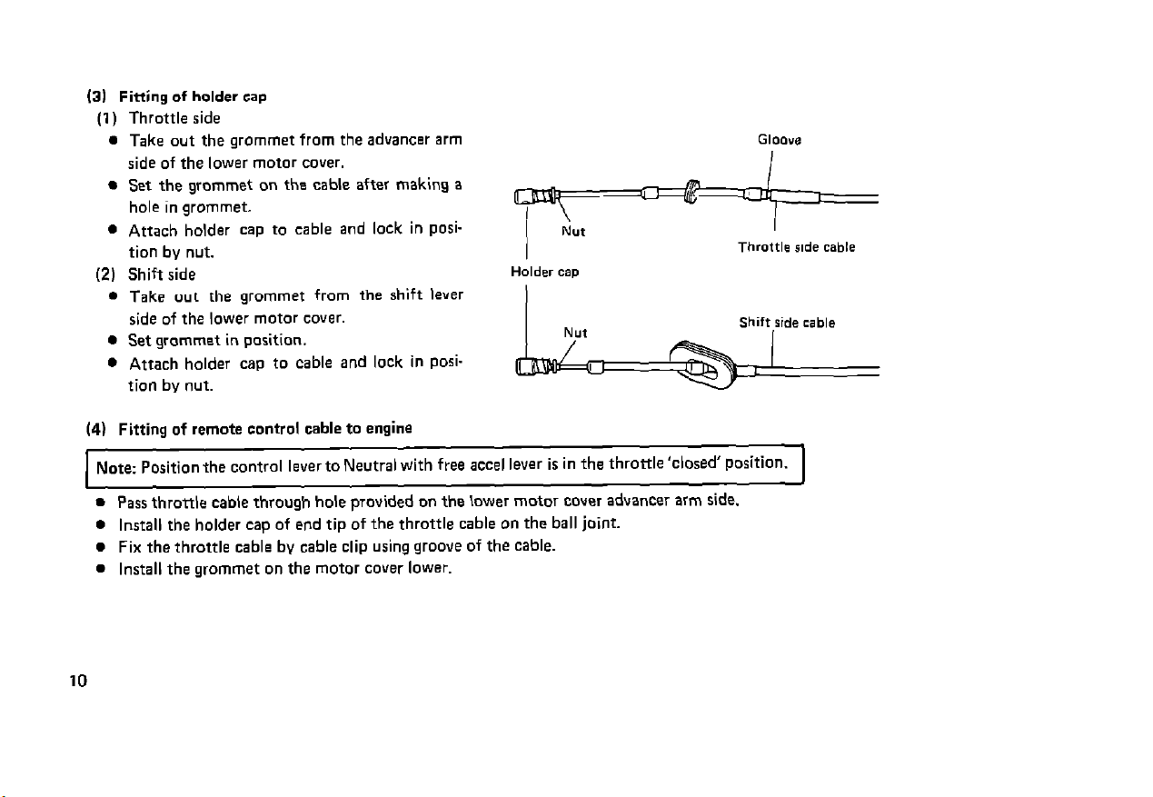
(31 Fitting of holder cap
(1) Throttle side
l
Take out the grommet from the advancer arm
side of the lower motor cover.
l
Set the grommet on the cable after making a I
hole in grommet.
l
Attach holder cap to cable and lock in PoSition by nut.
(2) Shift side
l
Take out the grommet from the shift lever
side of the lower motor cover.
l
Set grommet in position.
l
Attach holder cap to cable and lock in Posi-
Holder cap
Throttle ride cable
Shift ride cable
tion by nut.
(4) Fitting of remote control cable to engine
Note: Position the control lever to Neutral with free accel lever is in the throtde’closed’ Position.
l
Pass throttle cable through hole provided on the lower motor cover advancer arm side.
l
Install the holder cap of end tip of the throttle cable on the ball joint.
l
Fix the throttle cable by cable clip using groove of the cable.
. Install the grommet on the motor cover lower.
I
10
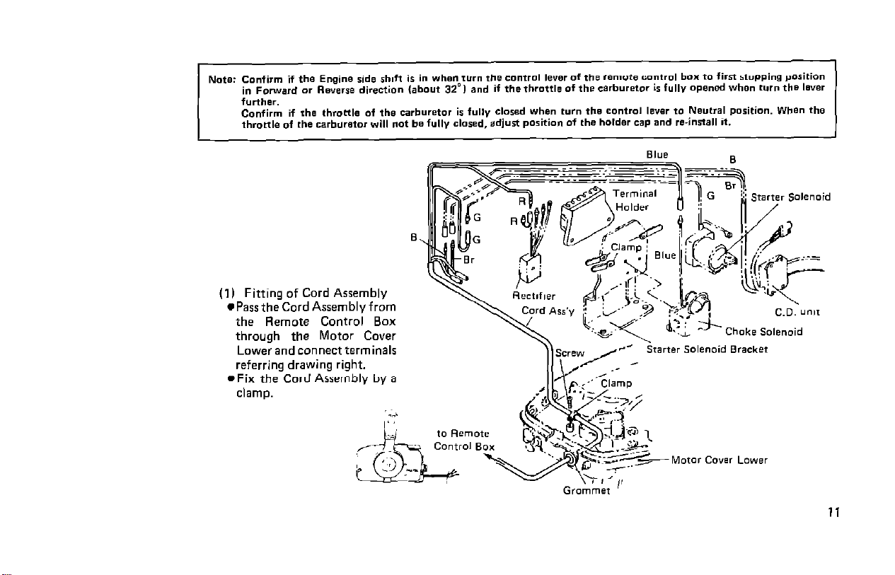
(1) Fitting of Cord Assembly
l Pass the Cord Assembly from
the Remote Control Box
through the Motor Cover
Lower and connect terminals
referring drawing right.
l
Fix the Cord Assembly by a
clamp.
11
l
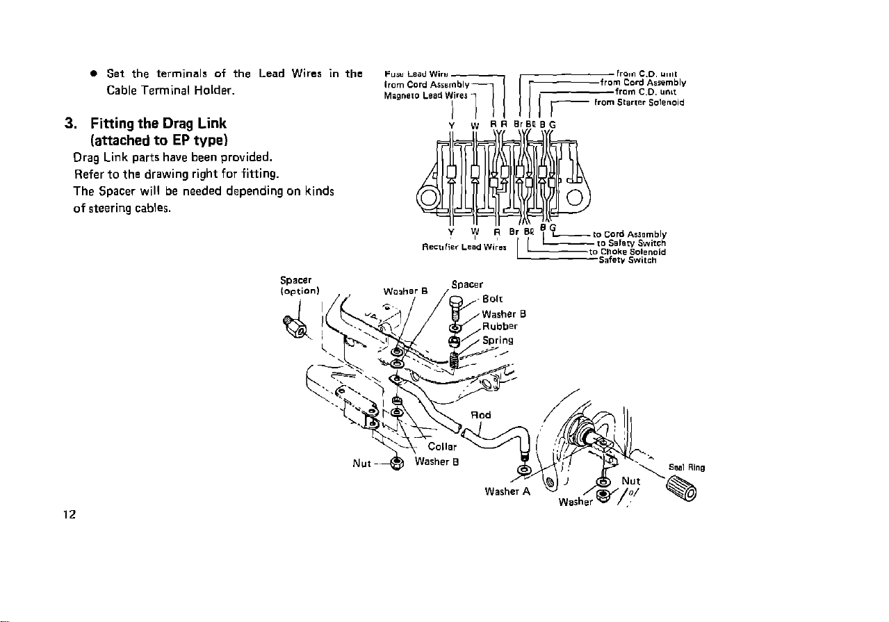
Set the terminals of the Lead Wires in the
Cable Terminal Holder.
3. Fitting the Drag Link
(attached to EP type)
Drag Link parts have been provided.
Refer to the drawing right for fitting.
The Spacer will be needed depending on kinds
of steering cables.
~~5s ~eadwirs
12
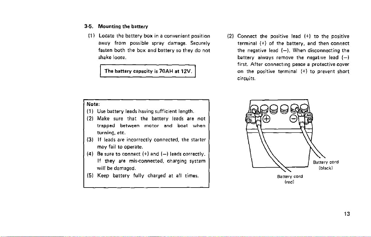
3.5. Mounting the battery
(11 Locate the battery box in a convenient position
away from possible spray damage. Securely
fasten both the box and battery so they do not
shake loose.
] The battery capacity is 70AH at 12V. 1
Note:
(1) Use battery leads having sufficient length.
(2) Make sure that the battery leads are not
trapped between motor and boat when
turning. etc.
(3) If leads are incorrectly connected, the starter
may fail to operate.
(4) Be sure to connect (+) and l-1 leads correctly.
If they are misxonnected. charging system
will be damaged.
(51 Keep battery fully charged at all times.
(21 Connect the positive lead (+I to the positive
terminal (+) of the battery. and then connect
the negative lead (6). When disconnecting the
battery always remove the negative lead (-1
first. After connecting peace a protective cover
on the positive terminal (+I to prevent short
circuits.
13
 Loading...