

TOHATSU MFS2.5B, MFS3.5B, 2.5B, 3.5B Owner's Manual
OWNER’S
MANUAL
MFS
2.5B
3.5B
OB No.003-11085-7
ENOM00001-0
READ THIS MANUAL BEFORE USING THE OUTBOARD MOTOR. FAILURE TO FOLLOW THE
INSTRUCTIONS AND SAFETY PRECAUTIONS IN THIS MANUAL CAN RESULT IN SERIOUS
INJURY OR DEATH. KEEP THIS MANUAL IN A SAFE LOCATION FOR FUTURE REFERENCE.
Copyright © 2009-2012 Tohatsu Corporation. All rights reserved. No part of this manual may be reproduced
or transmitted in any from or by any means without the express written permission of Tohatsu Corporation.

YOUR TOHATSU OUTBOARD MOTOR
ENOM00002-0
OWNER REGISTRATION AND IDENTIFICATION
Upon purchasing this product, be sure that the WARRANTY CARD is correctly and completely filled out and mailed to the addressee noted there on. This WARRANTY CARD
identifies you as the legal owner of the product and serves as your warranty registration.
TO THE EXTENT PERMITTED BY APPLICABLE LAW, YOUR OUTBOARD MOTOR WILL
NOT BE COVERED BY THE APPLICABLE LIMITED WARRANTY, IF THIS PROCEDURE IS
NOT FOLLOWED.
ENOM00003-0
PRE-DELIVERY CHECK
Be sure that the product has been checked by an authorized TOHATSU dealer before you
take delivery.
ENOM00004-0
Limited Warranty
Please refer to the TOHATSU outboard motor Limited warranty provided to you with this
product, the terms and conditions of which, as amended from time to time, are incorporated by reference into the manual.
3

4
ENOM00005-0
Serial Number
In the space below, please record the outboard motor’s serial number (indicated both on
the lower motor cover and on the cylinder block). The serial number will be needed in the
event of theft or to quickly identifying the outboard motor type.
Serial Number:
ENOM00006-0
To You, Our Customer
Thank you for selecting a TOHATSU outboard motor. You are now the proud owner of an
excellent outboard motor that will service you for many years to come.
This manual should be read in its entirety and the inspection and maintenance procedures
described later in this manual should be followed carefully. Should a problem arise with the
outboard motor, please follow the troubleshooting procedures listed at the end of this
manual. If the problem persists, contact an authorized TOHATSU service shop or dealer.
We hope you will enjoy your outboard motor and wish you good luck in your boating
adventures.
TOHATSU CORPORATION

CONTENTS
GENERAL SAFETY INFORMATION. . . . . . . . . . . . . . . . . . . . . . . . . . . . . . . . 8
1. SPECIFICATIONS . . . . . . . . . . . . . . . . . . . . . . . . . . . . . . . . . . . . . . . . . . . . . 10
2. NAMES OF PARTS . . . . . . . . . . . . . . . . . . . . . . . . . . . . . . . . . . . . . . . . . . . .11
3. LOCATIONS OF WARNING LABELS . . . . . . . . . . . . . . . . . . . . . . . . . . . . . .12
4. INSTALLATION . . . . . . . . . . . . . . . . . . . . . . . . . . . . . . . . . . . . . . . . . . . . . . . 14
1. Mounting the outboard motor on boat . . . . . . . . . . . . . . . . . . . . . . . . . . .14
5. PRE-OPERATING PREPARATIONS . . . . . . . . . . . . . . . . . . . . . . . . . . . . . .16
1. Recommended gasoline types . . . . . . . . . . . . . . . . . . . . . . . . . . . . . . . . .16
2. Low permeation fuel hose requirement . . . . . . . . . . . . . . . . . . . . . . . . . . .17
EQUIPPED FOR UNITED STATES AND CANADA MODEL
3. EPA pressurized fuel tank requirements . . . . . . . . . . . . . . . . . . . . . . . . . .18
EQUIPPED FOR UNITED STATES AND CANADA MODEL
4. Recommended engine oil . . . . . . . . . . . . . . . . . . . . . . . . . . . . . . . . . . . . . 18
5. Altitude adjustment kit requirement. . . . . . . . . . . . . . . . . . . . . . . . . . . . . .19
6. Break-In . . . . . . . . . . . . . . . . . . . . . . . . . . . . . . . . . . . . . . . . . . . . . . . . . . . 20
7. ESG (A device preventing over revolution). . . . . . . . . . . . . . . . . . . . . . . . . 21
6. ENGINE OPERATION . . . . . . . . . . . . . . . . . . . . . . . . . . . . . . . . . . . . . . . . . . 22
Before starting . . . . . . . . . . . . . . . . . . . . . . . . . . . . . . . . . . . . . . . . . . . . . . . . 22
1. Filling the fuel . . . . . . . . . . . . . . . . . . . . . . . . . . . . . . . . . . . . . . . . . . . . . . . 22
2. Feeding the fuel . . . . . . . . . . . . . . . . . . . . . . . . . . . . . . . . . . . . . . . . . . . . .24
3. Starting. . . . . . . . . . . . . . . . . . . . . . . . . . . . . . . . . . . . . . . . . . . . . . . . . . . . 24
4. Warming up the engine . . . . . . . . . . . . . . . . . . . . . . . . . . . . . . . . . . . . . . .27
5. Forward and reverse . . . . . . . . . . . . . . . . . . . . . . . . . . . . . . . . . . . . . . . . . 28
6. Stopping. . . . . . . . . . . . . . . . . . . . . . . . . . . . . . . . . . . . . . . . . . . . . . . . . . . 30
7. Trim angle . . . . . . . . . . . . . . . . . . . . . . . . . . . . . . . . . . . . . . . . . . . . . . . . .31
8. Tilt up, tilt down . . . . . . . . . . . . . . . . . . . . . . . . . . . . . . . . . . . . . . . . . . . . . 32
9. Outboard motor position in tilt up . . . . . . . . . . . . . . . . . . . . . . . . . . . . . . .33
7. REMOVING AND CARRYING THE OUTBOARD MOTOR. . . . . . . . . . . . . . 34
1. Removing the outboard motor. . . . . . . . . . . . . . . . . . . . . . . . . . . . . . . . . .34
2. Carrying the outboard motor . . . . . . . . . . . . . . . . . . . . . . . . . . . . . . . . . . .34
3. Storing the outboard motor . . . . . . . . . . . . . . . . . . . . . . . . . . . . . . . . . . . .34
8. TRAILERING . . . . . . . . . . . . . . . . . . . . . . . . . . . . . . . . . . . . . . . . . . . . . . . . . 35
9. ADJUSTMENT . . . . . . . . . . . . . . . . . . . . . . . . . . . . . . . . . . . . . . . . . . . . . . . . 36
1. Steering friction . . . . . . . . . . . . . . . . . . . . . . . . . . . . . . . . . . . . . . . . . . . . .36
2. Throttle grip . . . . . . . . . . . . . . . . . . . . . . . . . . . . . . . . . . . . . . . . . . . . . . . . 36
10. INSPECTION AND MAINTENANCE . . . . . . . . . . . . . . . . . . . . . . . . . . . . . . . 37
1. Daily Inspection . . . . . . . . . . . . . . . . . . . . . . . . . . . . . . . . . . . . . . . . . . . . . 38
2. Periodic Inspection . . . . . . . . . . . . . . . . . . . . . . . . . . . . . . . . . . . . . . . . . .43
3. Off-season storage . . . . . . . . . . . . . . . . . . . . . . . . . . . . . . . . . . . . . . . . . .46
4. Pre-season check . . . . . . . . . . . . . . . . . . . . . . . . . . . . . . . . . . . . . . . . . . . 47
5. Motor submerged in water. . . . . . . . . . . . . . . . . . . . . . . . . . . . . . . . . . . . . 47
6. Cold weather precautions . . . . . . . . . . . . . . . . . . . . . . . . . . . . . . . . . . . . .47
7. Checking after striking underwater object. . . . . . . . . . . . . . . . . . . . . . . . . 48

11. TROUBLESHOOTING . . . . . . . . . . . . . . . . . . . . . . . . . . . . . . . . . . . . . . . . . .49
12. TOOL KIT AND SPARE PARTS . . . . . . . . . . . . . . . . . . . . . . . . . . . . . . . . . . 51
13. OPTIONAL ACCESSORIES . . . . . . . . . . . . . . . . . . . . . . . . . . . . . . . . . . . . .52
14. PROPELLER TABLE . . . . . . . . . . . . . . . . . . . . . . . . . . . . . . . . . . . . . . . . . . .53
INDEX
7
GENERAL SAFETY INFORMATION
1. SPECIFICATIONS
2. NAMES OF PARTS
3. LOCATIONS OF WARNING LABELS
4. INSTALLATION
5. PRE-OPERATING PREPARATIONS
6. ENGINE OPERATION
7. REMOVING AND CARRYING THE
OUTBOARD MOTOR
8. TRAILERING
9. ADJUSTMENT
10.INSPECTION AND MAINTENANCE
11.TROUBLESHOOTING
12.TOOL KIT AND SPARE PARTS
13.OPTIONAL ACCESSORIES
14.PROPELLER TABLE
8
GENERAL SAFETY INFORMATION
ENOM00007-0
NOTICE: DANGER/WARNING/CAUTION/Note
Before installing, operating or otherwise handling your outboard motor, be sure to thoroughly read and understand this Owner’s Manual and carefully follow all of the instructions. Of particular importance is information preceded by the words “DANGER,”
“WARNING,” “CAUTION,” and “Note.” Always pay special attention to such information to
ensure safe operation of the outboard motor at all times.
ENOW00001-0
DANGER
Failure to observe will result in severe personal injury or death, and possibly property damage.
ENOW00002-0
WARNING
Failure to observe could result in severe personal injury or death, or property damage.
ENOW00003-0
CAUTION
Failure to observe could result in personal injury or property damage.
ENON00001-0
Note
This instruction provides special information to facilitate the use or maintenance of the outboard
motor or to clarify important points.
ENOM0008-0
EMERGENCY STOP SWITCH
The Emergency Stop Switch will stall the outboard motor when the stop switch tether is
pulled off. This stop switch tether can be attached to the operator of the outboard motor
to minimize or prevent injuries from the propeller in case the operator falls overboard.
We highly recommend use of the Emergency Stop Switch tether.
ENOW00004-0
WARNING
Accidental activation of the Emergency Stop Switch (such as the tether being pulled out in
heavy seas) could cause passengers to lose their balance and even fall overboard, or it
could result in loss of power in heavy seas, strong currents, or high winds. Loss of control
while mooring is another potential hazard.
To minimize accidental activation of the Emergency Stop Switch, the 500 mm (20 inch.) stop
switch tether is coiled and can extended to a full 1300 mm (51 inch.).
GENERAL SAFETY INFORMATION 9
ENOM00009-0
SAFE OPERATION OF BOAT
As the operator/driver of the boat, you are responsible for the safety of those aboard and
those in other boat around yours, and for following local boating regulations. You should
be thoroughly knowledgeable on how to correctly operate the boat, outboard motor, and
accessories. To learn about the correct operation and maintenance of the outboard motor,
please read through this manual carefully.
It is very difficult for a person standing or floating in the water to take evasive action should
he or she see a power boat heading in his/her direction, even at a slow speed. Therefore,
when your boat is in the immediate vicinity of people in the water, the outboard motor
should be shifted to neutral and shut off.
ENOW00005-0
WARNING
SERIOUS INJURY IS LIKELY IF A PERSON IN THE WATER MAKES CONTACT WITH A MOVING BOAT, GEAR HOUSING, PROPELLER, OR ANY SOLID DEVICE RIGIDLY ATTACHED TO
A BOAT OR GEAR HOUSING.
ENOM00010-0
SERVICING, REPLACEMENT PARTS & LUBRICANTS
We recommend that only an authorized service shop perform service or maintenance on
this outboard motor. Be sure to use genuine parts, genuine lubricants, or recommended
lubricants.
ENOM00011-0
MAINTENANCE
As the owner of this outboard motor, you should be acquainted with correct maintenance
procedures. It is the operator’s responsibility to perform all safety checks and to ensure
that all lubrication and maintenance instructions are complied with for safe operation.
Please comply with all instructions concerning lubrication and maintenance. You should
take the engine to an authorized dealer or service shop for periodic inspection at the prescribed intervals.
Correct periodic maintenance and proper care of this outboard motor will reduce the
chance of problems and limit overall operating expenses.
ENOM00012-0
MOUNTING
Outboard motor mounting must be performed by trained service person(s) using lift or
hoist with sufficient capacity.
10
SPECIFICATIONS
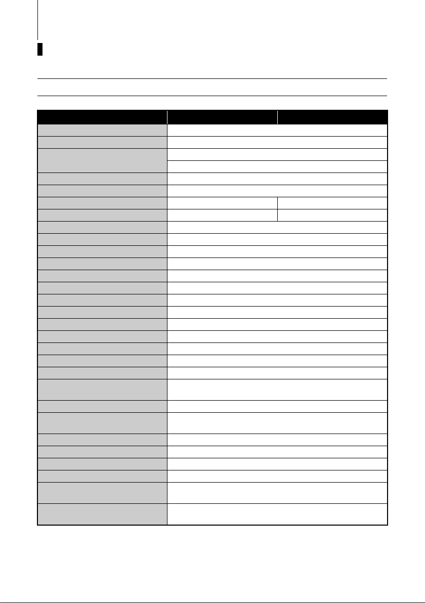
EENOM00201-0
2.5B, 3.5B
Item MODEL 2.5B 3.5B
Overall Length mm (in) 690 (27.2)
Overall Width mm (in) 363 (14.3)
Overall Height S·L mm (in)
Transom Height S·L mm (in) 435 (17.1) 562 (22.1)
Weight S·L kg (lb) 18.4 (41) 19.4 (43)
Output kW (ps) 1.8 (2.5) 2.6 (3.5)
Max. Operating Range rpm 4500–5500 5000–6000
Idle Speed in Forward Gear rpm 1200
Idle Speed in Neutral Gear rpm 1300
Engine Type 4-Stroke
Number of Cylinder 1
Bore × Stroke mm (in) 55 × 36 (2.17 × 1.42)
Piston Displacement mL (Cu in) 85.5 (5.2)
Exhaust System Above propeller exhaust
Cooling System Water cooling
Engine Lubrication Splashing system
Starting System Manual starter
Ignition System Ignitor
Spark Plug NGK DCPR6E
Tri m Po sitio n 4
Engine Oil mL (fl.oz.)
Gear Oil mL (fl.oz.) Genuine Gear Oil or API GL5, SAE #80-90, Approx. 180 (6.1)
Fuel
Clutch Dog clutch system (F-N)
Fuel Tank Capacity L (US gal) 1.0 (0.26) Integral tank
Gear Reduction Ratio 2.15 (13 : 28)
Emission Control System EM (Engine modification)
Operator Sound Pressure
(ICOMIA 39/94) dB (A)
Hand Vibration Level
(ICOMIA 38/94) m/sec2
Remark: Specifications subject to change without notice.
Except for USA and Canada model 1026 (40.4) 1153 (45.4)
For USA and Canada model 1040 (40.9) 1167 (45.9)
NMMA FC-W certified 10W-30 or
API SF, SG, SH, SJ, SL or SM, Approx. 300 (10)
Unleaded regular gasoline : Pump posted 87 Octane
(research octane rating of 91)
80.1
8.9
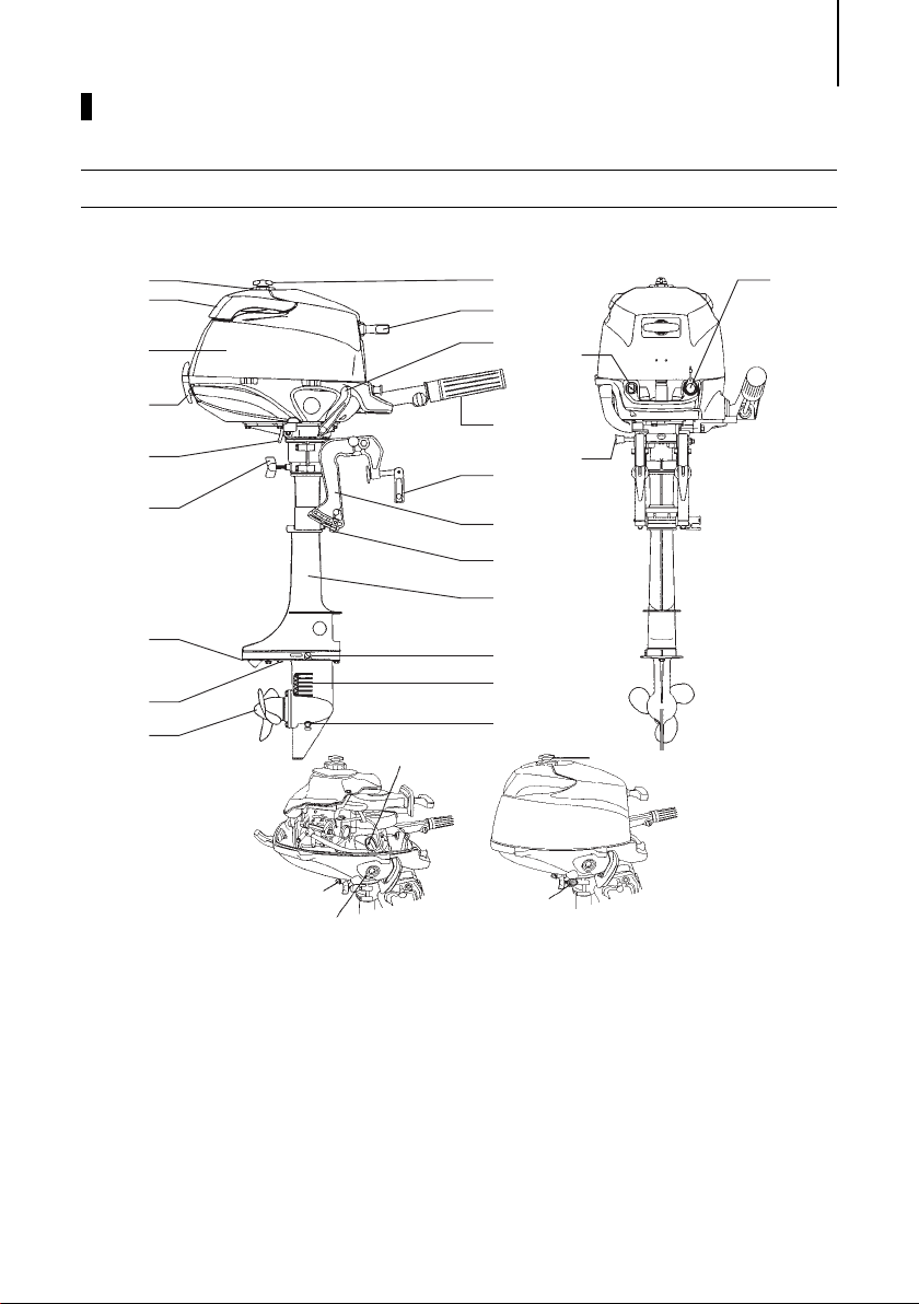
NAMES OF PARTS
1
2
3
8
9
11
10
13
14
15
16
19
17
18
21
20
22
12
4
5
6
7
23
24
25
26
28
27
A
ENOF00201-0
ENOM00202-0
2.5B, 3.5B
11
1
Fuel Tank Cap
2
Tilt Handle
3
Top C owl
4
Cowl Latch
5
Cooling Water Check Port
6
Steering Adjustment Screw
7
Anti Ventilation Plate
8
Anode
9
Propeller
10
Oil Plug (Lower) (Fill)
11
Water Inlet
12
Oil Plug (Upper) (Level)
13
Drive Shaft Housing
14
Thrust Rod
15
Clamp Bracket
16
Clamp Screw
17
Throttle Grip
18
Shift Lever
19
Starter Handle
20
Air Vent Screw
21
Choke Knob
22
Stop Switch
23
Tilt Stopper
24
Engine Oil Filler Cap
25
Engine Oil Drain Screw
26
Engine Oil Level Gauge
27
Air Vent Screw
28
Fuel Cock
A
: Integral Fuel Tank
12
2
4
3
1
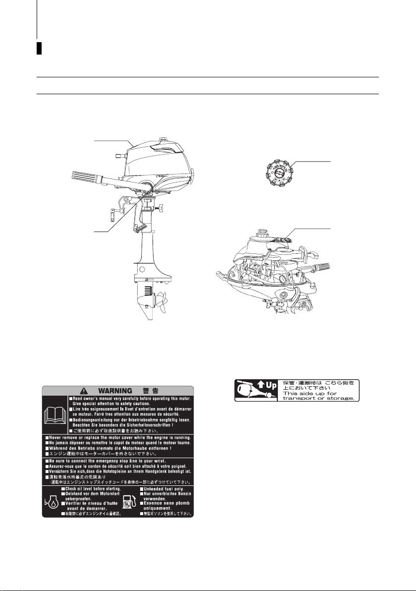
ENOF00202-0
LOCATIONS OF WARNING LABELS
ENOM00203-0
Locations of warning labels
1.
Warning label regarding owner’s manual, top cowl, engine stop switch,
engine oil level and unleaded gasoline.
ENOF00005-0
2.
Warning label on position of outboard
motor when setting down.
3.
Only for USA and CANADA models
ENOF00253-0
Warning regarding fuel tank cap (See
pages 22–24).
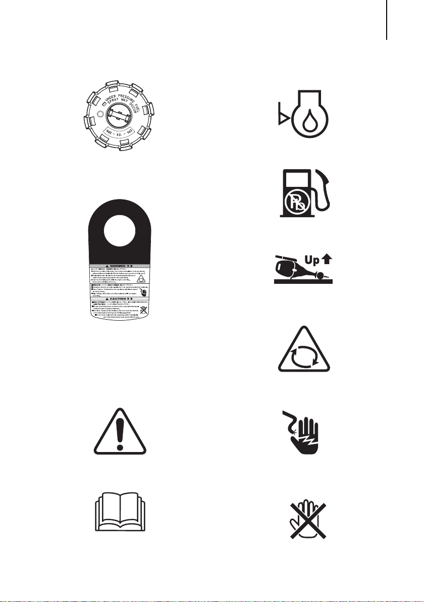
4.
ENOF00012-0
ENOF00254-0
ENOF00114-0
ENOF00115-0
ENOF00117-0
Rotating part, high voltage, high temperature warning label.
LOCATIONS OF WARNING LABELS 13
Check oil level
ENOF00116-0
Use unleaded gasoline only
Lay as indicated
ENOF00203-0
Warning, rotating object
ENOM00204-0
Symbols
Individual symbol marks means as
described below.
Warning/Caution
Read manual thoroughly
ENOF00249-0
Warning, high voltage
ENOF00204-0
Warning, high temperature
ENOF00205-0
14
1
ENOF00207-0
INSTALLATION
ENOM00024-0
1. Mounting the outboard motor on
boat
ENOW00006-0
WARNING
Most boats are rated and certified in terms
of their maximum allowable horsepower,
as shown on the boat’s certification plate.
Do not equip your boat with an outboard
motor that exceeds this limit. If in doubt,
contact your dealer.
Do not operate the outboard motor until it
has been securely mounted on the boat in
accordance with the instructions below.
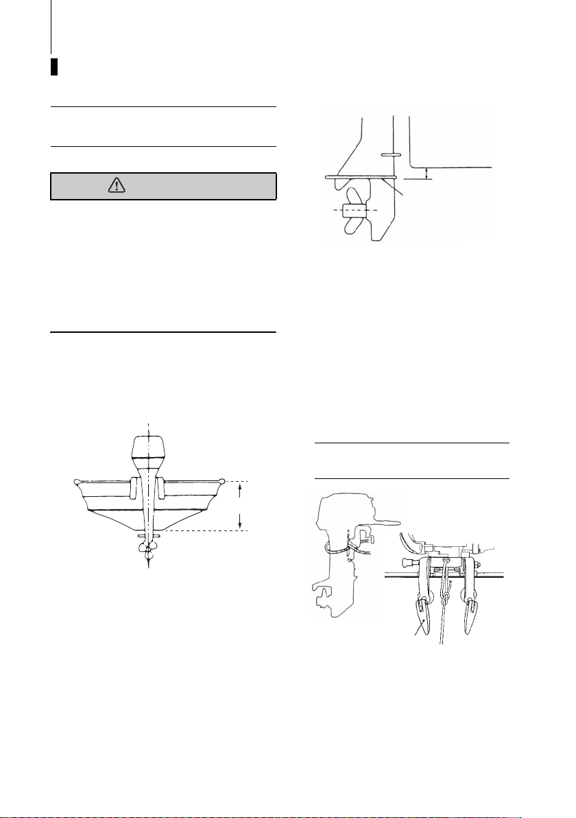
ENOM00025-0
Position ... Above keel line
Set engine at center of boat.
1
1
30–50 mm
(1.2–2 in)
2
ENOF00206-0
1. Bottom of hull
2. Anti ventilation plate
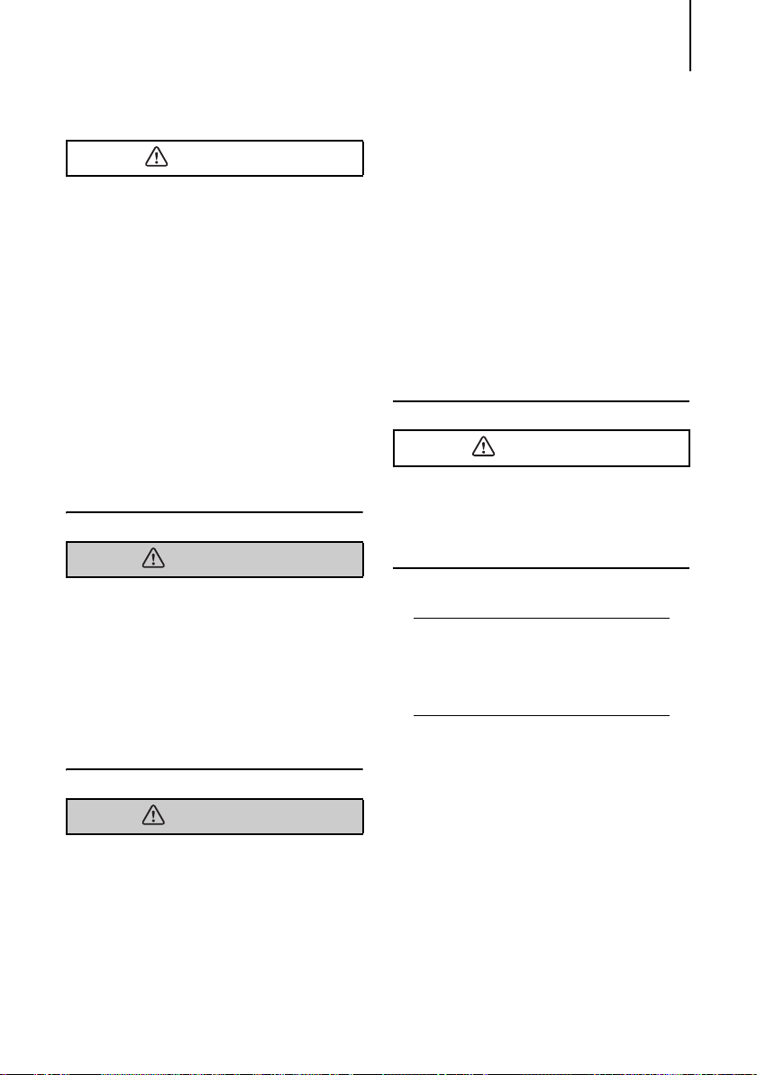
To attach the outboard motor to the boat,
tighten the clamp screws by turning their
handles.
Also, use the bolts to secure the outboard
motor brackets on transom board.
Secure the outboard motor with a rope to
prevent loss overboard.
ENON00002-0
Note
A rope is not included in the standard
accessories.
2
ENOF00014-0
1. Center of boat
2. Boat transom
ENOM00204-0
Transom matching
Be sure that the anti ventilation plate of the
outboard motor is below the water surface.
If the above condition cannot be met due
to the shape of the bottom of your boat,
please consult your authorized dealer.
1. Clamp screw
INSTALLATION 15
ENOW00007-0
CAUTION
Before beginning the running test, check
that the boat with maximum capacity
loading floats on the water in a proper
attitude. Check the position of water
surface on the driveshaft housing. If the
water surface is near the bottom cowling, in high waves, water may enter the
engine cylinders.
Incorrect outboard motor mounting
height or existence of underwater
object(s), such as hull bottom design,
bottom surface conditions or underwater accessories, can cause water spray
possibly reaching the engine through an
opening of the bottom cowling during
cruising. Exposing the engine to such
conditions for extended periods can
lead to severe engine damage.
ENOW00213-0
WARNING
If the length of security line being used is
long enough to allow the outboard to disengage off the boat transom but is too
short to not allow the outboard to submerge behind the boat and stop running,
the outboard could continue running and
propel itself back into the boat with the
propeller rotating under power. This
exposes the occupants to serious injury or
death.
personal injury. Be sure that fasteners
are tightened to the specified torque (30
Nm (3.0 kgf) 13 ft-lb). Check the fasteners for tightness from time to time.
Be sure to use outboard mounting fas-
teners included in the outboard motor
package or their equivalents in terms of
size, material, quality and strength.
Tighten fasteners to the specified torque
(30 Nm (3.0 kgf) 13 ft-lb). Test cruise to
check if fasteners are tightened
securely.
Outboard motor mounting must be per-
formed by trained service person(s)
using lift or hoist with sufficient capacity.
ENOW00008-0
CAUTION
Mounting bolts should be installed with the
bolt head at inside surface of the transom.
Mounting bolts installed with the threaded
end at the inside surface of the transom
can cause personal injury.
ENON00201-0
Notes
1. Apply sealing agent such as silicone
sealed between bolts and transom
board holes before tightening bolts.
2. Be sure to tighten mounting bolt nuts to
specified torque.
ENOW00009-0
WARNING
Mounting the outboard motor without
following this manual can lead to unsafe
conditions such as poor maneuverability, lack of control or fire.
Loose clamp screws and/or mounting
bolts can lead to the release or displacement of the outboard motor, possibly
resulting in lost of control and/or serious
16
PRE-OPERATING PREPARATIONS
ENOW00016-0
DANGER
Consult an authorized dealer for details on
handling gasoline, if necessary.
Gasoline and its vapors are very flammable
and can be explosive.
When carrying a fuel tank containing gasoline:
Close the air vent screw of fuel tank cap,
or gasoline vapor will be emitted
through the air vent screw, creating a
fire hazard.
Do not smoke.
When or before refueling:
Stop the engine, and do not start the
engine during refueling.
Do not smoke.
Be careful not to overfill fuel tank. Wipe
up any spilled gasoline immediately.
When or before cleaning the gasoline tank:
Dismount fuel tank from the boat.
Place the fuel tank away from every
source of ignition, such as sparks or
open flames.
Do the work outdoors or in a well venti-
lated area.
Wipe off gasoline well immediately if
spilt.
After cleaning gasoline tank:
Wipe off gasoline well immediately if
spilt.
If the fuel tank is disassembled for
cleaning, reassemble carefully. Imperfect assembly may cause a fuel leak,
possibly leading to fire or explosion.
Dispose aged or contaminated gasoline
in accordance with local regulations.
ENOM00030-0
1. Recommended gasoline types
ENOW000017-0
CAUTION
Use of improper gasoline can damage your
engine. Engine damage resulting from the
use of improper gasoline is considered
misuse of the engine, and damage caused
thereby will not be covered under the limited warranty.
ENOM00031-0
FUEL RATING
TOHATSU engines will operate satisfactorily when using a major brand of unleaded
gasoline meeting the following specifications:
USA and Canada — having a posted
pump Octane Rating of 87 (R+M)/2 minimum. Premium gasoline (92 [R+M]/2
Octane) is also acceptable. Do not use
leaded gasoline.
Outside USA and Canada — Use
unleaded gasoline with declared octane
rating of 90 RON or over. Use of premium
gasoline of 98 RON is also allowed. Use of
name-brand leaded gasoline may be
allowed only if unleaded gasoline is not
available.
ENOM00205-0
GASOLINES CONTAINING
ALCOHOL
The fuel system components on your
TOHATSU engine will withstand up to 10%
alcohol content in the gasoline. But if the
gasoline in your area contains either methanol (methyl alcohol) or ethanol (ethyl alcohol), you should be aware of certain
PRE-OPERATING PREPARATIONS 17
adverse effects that can occur. These
adverse effects are more severe with
methanol. Increasing the percentage of
alcohol in the fuel can also worsen these
adverse effects. Some of these adverse
effects are caused because the alcohol in
the gasoline can absorb moisture from the
air, resulting in a separation of the water/
alcohol from the gasoline in the fuel tank.
These may cause increased:
Corrosion of metal parts
Deterioration of rubber or plastic parts
Fuel permeation through rubber fuel
lines
Starting and operating difficulties
ENOW00018-0
WARNING
Fuel leakage can cause fire or explosion,
potentially leading to severe injury or loss
of life. Every fuel system part should be
checked periodically, and especially after
long term storage, for fuel leak, change of
hardness of rubber, expansion and/or corrosion of metals. In case any indication of
fuel leakage or degradation of fuel part is
found, replace relevant part immediately
before continuing operation.
If the use of gasoline containing alcohol is
inevitable, or presence of alcohol is suspected in the gasoline, it is recommended
to add a filter that has water separating
capability, and check the fuel system for
leaks and mechanical parts for corrosion
and abnormal wear more frequently.
And, in case any of such abnormality is
found, discontinue the use of such gasoline and contact our dealer immediately.
Damages resulting from the use of gasolines that contain alcohol are not covered
under the limited warranty.
ENOW00019-0
WARNING
Do not fill the fuel tank over capacity. The
rise of gasoline temperature may cause
gasoline to expand which, if overfilled, may
leak through air vent screw when it is open.
Leaking gasoline is a dangerous fire hazard.
ENOW00020-0
CAUTION
When operating a TOHATSU engine on
gasoline containing alcohol, storage of
gasoline in the fuel tank for long periods
should be avoided. Long periods of storage, common to boats, create unique problems. In cars, alcohol blend fuels normally
are consumed before they can absorb
enough moisture to cause trouble, but
boats often sit idle long enough for phase
separation to take place. In addition, internal corrosion may take place during storage if alcohol has washed protective oil
films from internal components.
ENOM00033-0
2. Low permeation fuel hose
requirement
EQUIPPED FOR UNITED STATES AND
CANADA MODEL
Required for outboards manufactured for
sale, sold, or offered for sale in the United
States.
TOHATSU engine has used fuel hoses
for The Environmental Protection
Agency (EPA) requires from January 1,
2011.
 Loading...