

TOHATSU 9.9D, 15D, 18E Owner's Manual
TOHATSU
OUTBOARDS
OWNER’S MANUAL

Copyright © 2007 Tohatsu Corporation. All rights reserved. No part
of this manual may be reproduced or transmitted in any form or by
any means without the express written permission of Tohatsu
Corporation.

YOUR TOHATSU OUTBOARD MOTOR
OWNER REGISTRATION AND IDENTIFICATION
Upon purchasing this product, be sure your dealer* fills out the WARRANTY
CARD correctly and complerely and malls It to the distributor. This card identifies you as the legal owner of the product and serves as your warranty registra-
tion~
If this procedure is not followed, your outboard motor will not be covered by
warranty.
*: In this manual, “dealer” always means an authorized TOHATSU dealer.
PRE-DELIVERY CHECK
Be sure that the product has been checked by the dealer before the delivery.
LIMITED WARRANTY
This TOHATSU product is fully guaranteed against defective materials and
workmanchip for the period from the date of purchase, provided that the pur-
chase has been registered in accordance wth the above.
The limited warranty wdl not apply to the normal wear and tear of pats, adlust-
merits, tune-ups, or to any damage caused by:
I) Uw or operation NOT conforming to the instruction? described in this own-
er’s manual,
2) Participation in or preparation for racing or other competitive activities,
3) Water entering the engine or the engme room,
4) Damage of an accident,, collisions, contact with foreign materials, or submersion.
5) Growth of marine organisms on motor surfaces.
6) Any other careless use or operation.
7) Normal deterioratlon~
The limited warranty does not cover maintenance items. The following items are
some examples not to be covered by the limited warranty.
spark plug?, anode. [rim-tub, propeller, fuel filter, oil filter, carbon brush, starter
rope, shear-pin, split-pin, bolt-nut-wayher, wre cable, lubber goods: pump impeller, oil seal, “0’.ring, fuel pipe, primer bulb, etc., vinyl tube
The warranty will become void iE the product has been altered, modified, or re-
pared by anyone other than a company or service firm authorized by
TOHATSU.
The warranty will cover only your TOHATSU product and will not cc&the
boat the product is mounted on. the trailer, equipment, or accessories associated
with the product.
Serial Number
In the space below, please record the engine’s serial number (indicated both on
the lower motor cover and on the cylinder block). This number will come in
handy in the event of theft or to help in quickly identifying the product type.
Serial Number:
To You, Our Customer:
Thank you for selecting a TOHATSU product. You are now the proud owner of
an excellent outboard engine that will serve you for many years to come.
We would like to point out that carefree usage can only be assured on condition
that this manual is read through in its entirety and the maintenance routines de-
scribed later in this manual are followed carefully. Should difficulty arise with
the engine, please follow the troubleshooting procedures listed at the end of this
manual. If the problem persists, contact an authorized TOHATSU service shop
or your dealer.
We hope you will get much enjoyment from this product and wish you good
luck in your boating adventures.
TOHATSU CORPORATION
NOTICE: DANGER/WARNING/CAUTION/Note
Before operating your outboard motor, be sure to thoroughly read and understand this Owner’s Manual and follow all of the instructions shown. Of particular importance is information preceded by the words “DANGER,”
“WARNING,” “CAUTION,” and “Note.” Always pay special attention to such
information to ensure safer and trouble-free operation at all times.
Failure to observe will result in severe personal injury or death.
I

AWARNING
,,..........: .i_ii
could result in severe personal injury or death.
A
CAUTION
Failure to observe could result in minor personal injury or product or
property damage.
Note:
This instruction provides special information to facilitate the use or
maintenance of the outboard or to clarify important points.
EMERGENCY STOP SWITCH
The stop switch will cut off the engine when the stop switch line is pulled out.
This line can be attached to the body of the operator, effectively preventing inju-
ries from the propeller m case he/she falls overboard.
We highly recommend use of the stop switch line because it can save the life of
the operator if somethings bad happens. However, we would also like to point
out the drawbacks of the switch. Accidental activation of the switch (such as the
line being pulled out in heavy seas) could cause passengers to lose their balance
and even fall overboard, or it could result in loss of power in heavy seas, strong
cunents, or high winds. Loss of control while mooring is another potential hazard.
I
To prevent such hazardous situations, the SO0 mm line is coiled and can extend
to a full 1,300 mm.
WARNINGS
As the operator/driver of the boat, you are responsible for the safety of those
aboard and those in other crafts around yours, and for following local boating
regulations. Therefore you should possess thorough knowledge of correct opera-
tlon of the boat, its accessories, and the engine. To learn about the correct opera-
tion and maintenance of the engine, please read through this manual carefully.
It is very difficult for a person standing or floating in the water to take evasive
action should he or she see a power boat heading in his/her direction, even at a
slow speed. Therefore, when your boat is in the immediate vicinity of people in
the water, the engine should be shifted to neutral and shut off.
SERIOUS INJURY IS LIKELY IF A PERSON IN THE WATER MAKES
CONTACT WITH A MOVING BOAT, GEAR HOUSING, PROPELLER, OR
ANY SOLID DEVICE RIGIDLY ATTACHED TO A BOAT OR GEAR HOUSING.
It is the operator’s responsibility to perform all safety checks and to ensure that
all lubrication and maintenance instructions are complied with for safe operation. It is also the operator’s responsibility to return the unit to the local dealer
for periodic inspection.
Cowct periodic maintenance and good care of this outboard engine will lessen
the chance of problems and keep overall operating expenses at a minimum.
SERVICING, REPLACEMENT PARTS, & LUBRICANTS
Only let an authorized TOHATSU service shop perform servicing or maintenance on this producr. Be sure to use genuine parts and genuine lubricants or
recommended lubricants.
MAINTENANCE
As the owner of this outboard engme, you should be acquainted with its correct
maintenance. Please comply with all instructions on lubrication and maintenance, and return the engine to the dealer or service shop for periodic inspection
at the prescribed intervals.
Troublefree operation cannot be expected unless the engine receives adequate
periodic maintenance. If maintenance is performed periodically, it is not likely
that a costly overhaul wll ever be required.
USE OF SERVICE SHOP
When subjecting your TOHATSU product to a check or repair, please be sure to
use a TOHATSU dealer authorized by TOHATSU or a TOHATSU agent.
CONTENTS
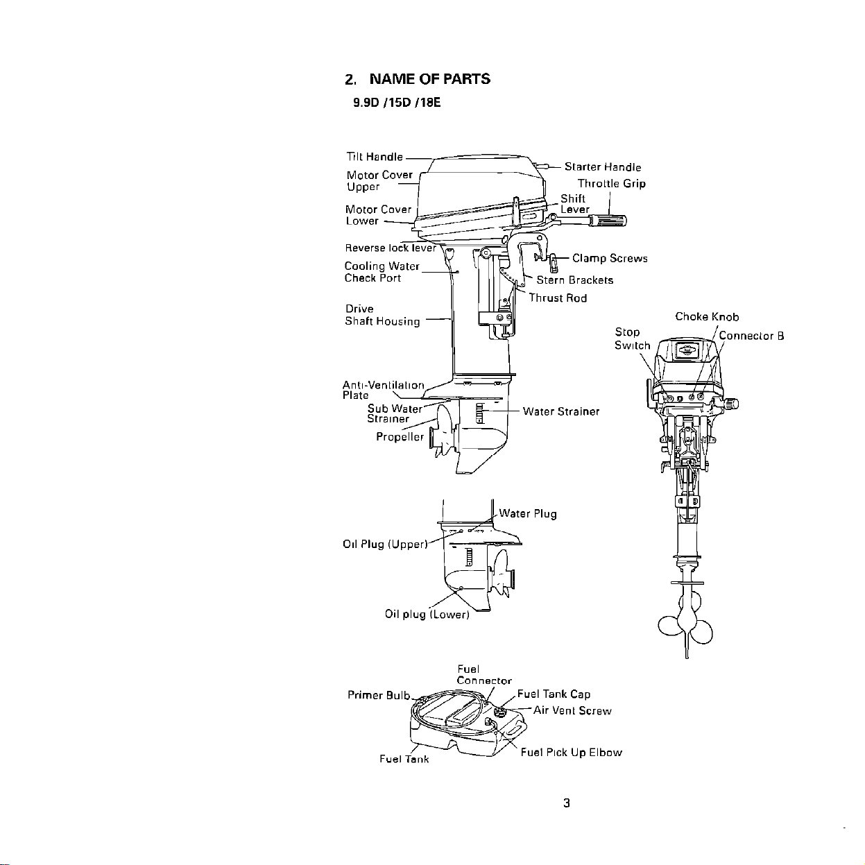
2. NAME OF PARTS
9.9D /15D ll8E
Drive
Shaft Housing -
pl&“’ n t
Sub
Stral
Propeller -\
‘W
-
Choke Knob
S
S,
‘Water Strainer
Tank Cap
ir Vent Screw
Fuel PI& Up Elbow
3
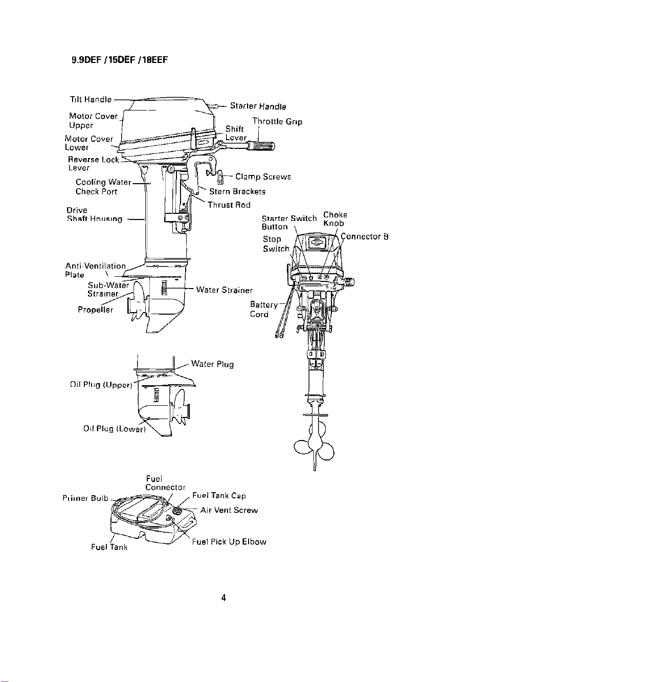
9.9DEF /15DEF /IBEEF
Reverse Lock
Drive
Shaft tiousmg -
Clamp Screws
?I-~
stern BE
Thrust Rod
Primer Bulb
ir Vent Screw
Fuel Pick Up Elbow
4
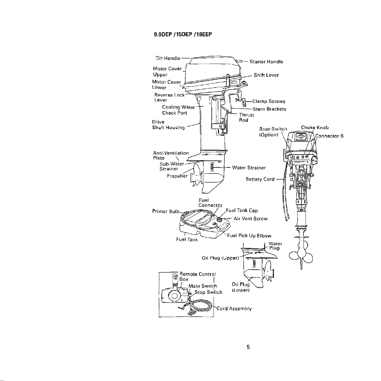
9.9DEP /15DEP /lEEEP
Tilt Handle
Motor Cove
UPPer
Rod
Stoo Switch
(Option)
Choke Knol
I I
I Tank Cap
Air Vent Screw
el Pick Up Elbow

3. INSTALLATION
A
WARNING
Most boats are rated and certified in terms of their maximum horse-
power, and this is shown on the boat’s certification plate. Do not equip
your boat with an outboard that exceeds this limit. If in doubt, contact
your dealer.
Do not operate the engine unit until it has been securely mounted on
the boat in accordance with the instructions below.
3-l. Mounting enginels) on boat
(1) Position above keel line
l
Set engine center of boat
(Fig. I)
l
Distance between engines if
two are mounted approxi-
mately 560 mm (22.8”)
(2) Transom matching
Be sure that the anti-ventila-
tion plate of the outboard is
below the water surface
when running with the
throttle wide open. (Fig. 2)
If the above condition cannot be met due to the shape
of the bottom of your boat,
please consult the dealer.
Bottom of hull
3040mm
c
11.2~2”)
Anti-Ventilation
Fig. 2
(3) To attach the engine to the
boat,
screws by turning their handles. Also, tighten the bolts.
(Fig. 3a)
Make sure the engine is secure (Fig. 3b) to prevent loss
or damage.
tighten the clamp
Washer
6
Fig. 3a
“v
Fig. 3b
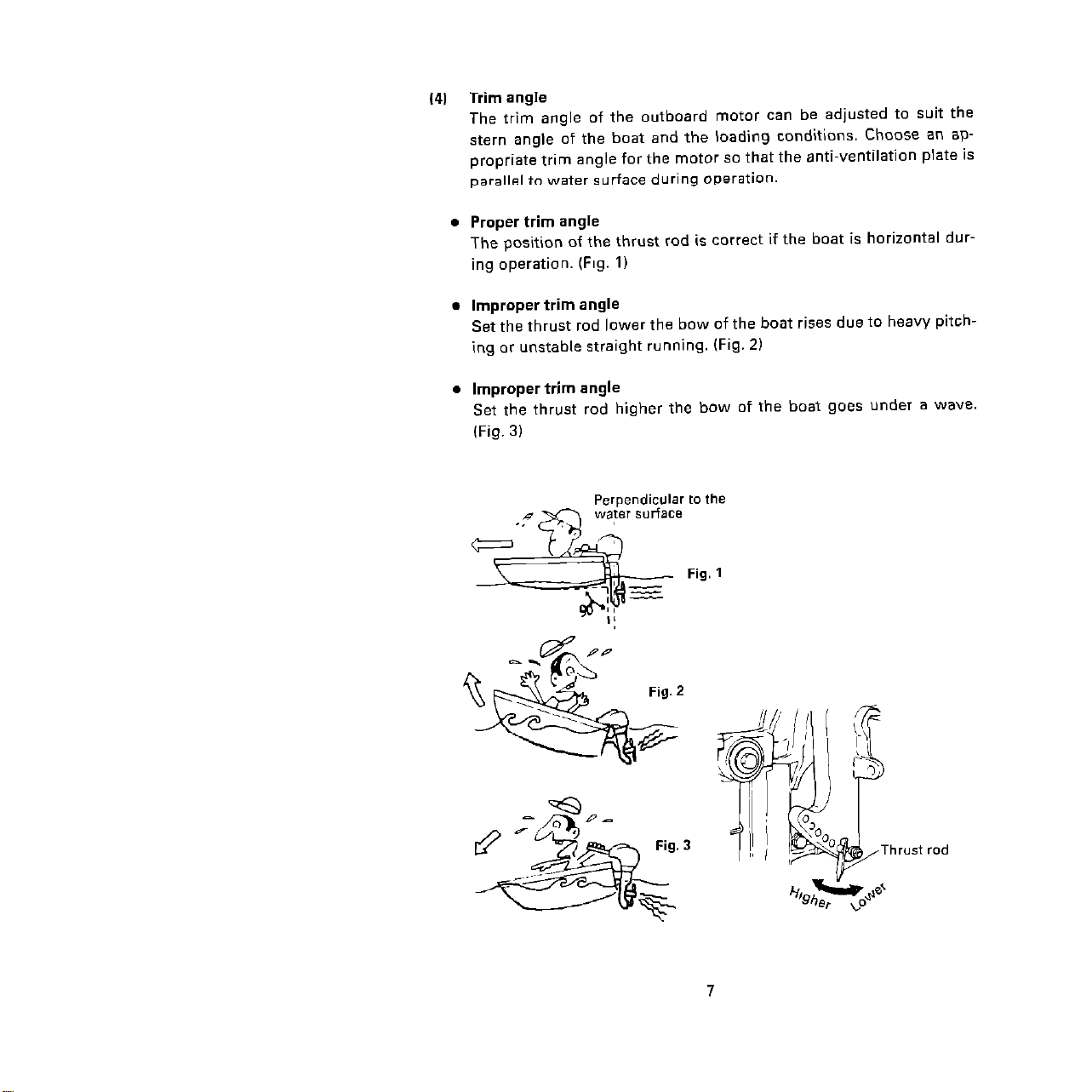
(4) Trim angle
The trim angle of the outboard motor can be adjusted to suit the
stern angle of the boat and the loading conditions. Choose an appropriate trim angle for the motor so that the anti-ventilation plate is
parallel to water surface during operation.
l
Proper trim angle
The position of the thrust rod is correct if the boat is horizontal dur-
ing operation. (Fig. I)
l
Improper trim angle
Set the thrust rod lower the bow of the boat rises due to heavy pitch-
ing or unstable straight running. (Fig. 2)
.
Improper trim angle
Set the thrust rod higher the bow of the boat goes under a wave.
(Fig. 3)
Perpendicular to the
Fig. 1

3-2. Installing the remote control device
The following is an explanation of a right-hand Remote Control Box.
(1) Position of the Remote Control Box and length of the Remote Con-
trol Cable.
@I Decide where to install the Remote Control
Box, there should be no obstruction in operating the Remote
Control Lever or switches.
Check if there is any obstruction for the Remote Control Cables.
(Fig. 1 & 2)
@ The length differs depending on the type of boat.
To determine your length, measure the distance between points
A and B in Fig. 3 and add 300 mm (I foot) to that number. This is
your length. (Fig. 3)
Note:
Do not roll up the Remote Control Cable to a diameter less than 406
mm (16 inches).
See note on Page 12.1
Control lever
Neutral warm-up
Outboard motor
center
Fig. 3
8
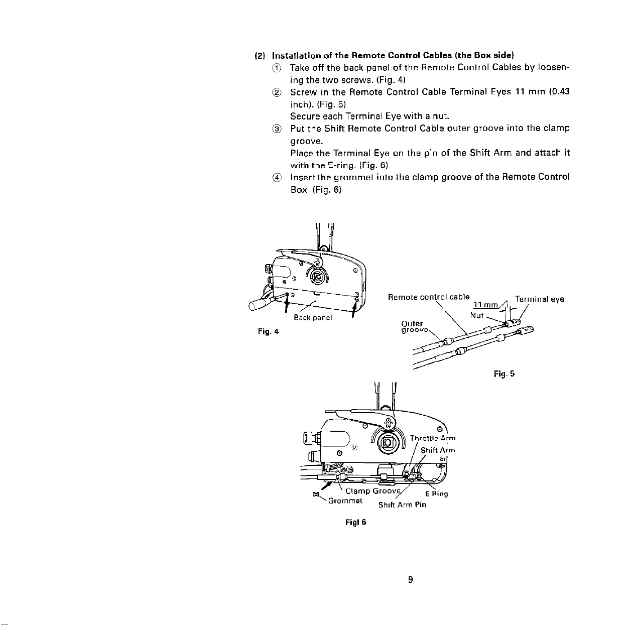
(21 Installation of the Remote Control Cables (the Box side)
0 Take off the back panel of the Remote Control Cables by loosen-
ing the two screws. (Fig. 4)
@ Screw in the Remote Control Cable Terminal Eyes 11 mm (0.43
inch). (Fig. 5)
Secure each Terminal Eye with a nut.
@ Put the Shift Remote Control Cable outer groove into the clamp
groove.
Place the Terminal Eye on the pin of the Shift Arm and attach it
with the E-ring. (Fig. 6)
@ Insert the grommet into the clamp groove of the Remote Control
Box. (Fig. 61
Fig. 4
Fig. 5
3
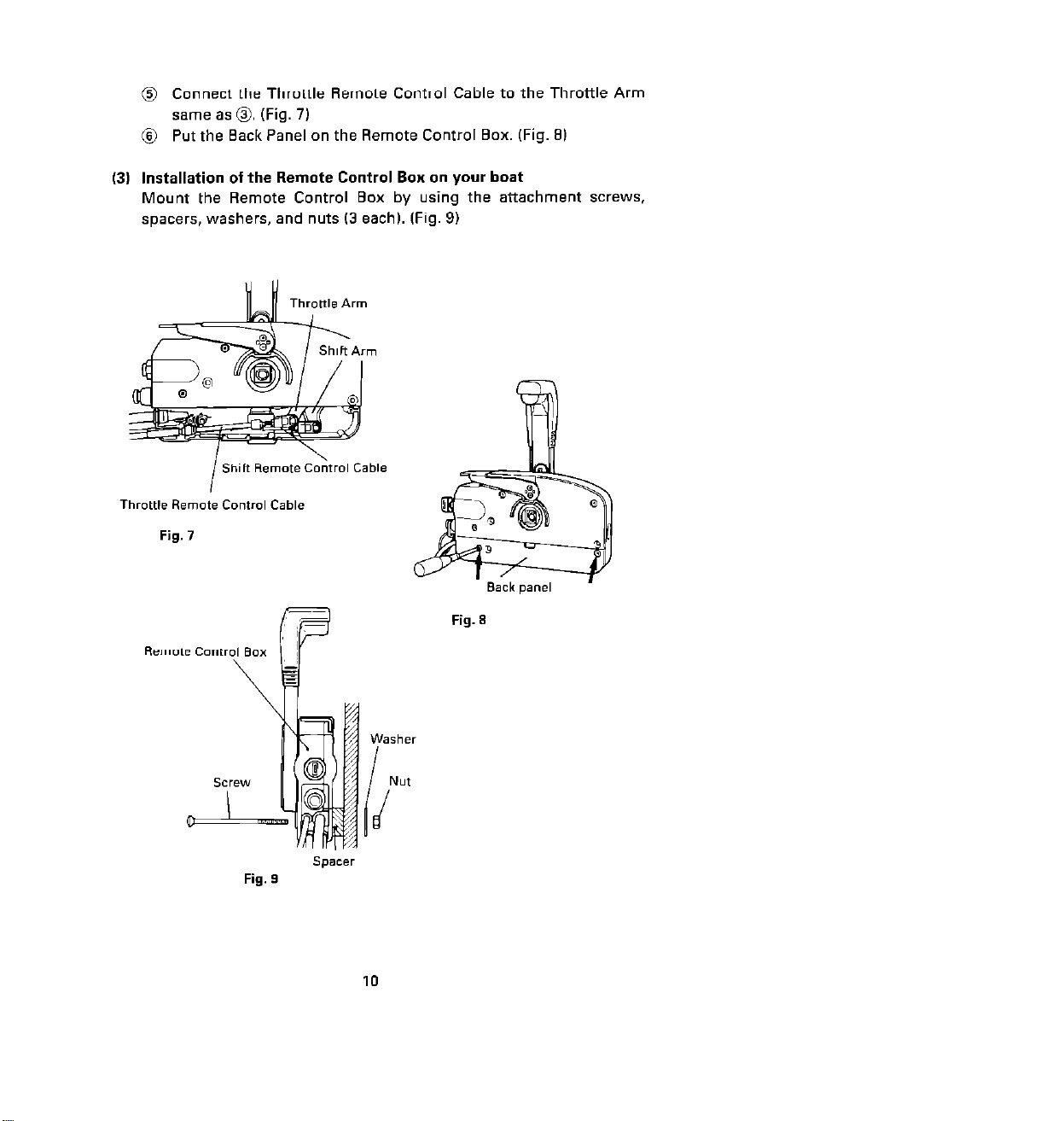
@ Connect the Throttle Remote Control Cable to the Throttle Arm
same as 0. (Fig. 7)
@ Put the Back Panel on the Remote Control Box. (Fig. 91
(3) Installation of the Remote Control Bon on your boat
Mount the Remote Control Box by using the attachment screws,
spacers, washers, and nuts (3 each). (Fig. 9)
m
Throttle Remote Control Cable
Fig. 7
Fig. 9
Fig. 8
10
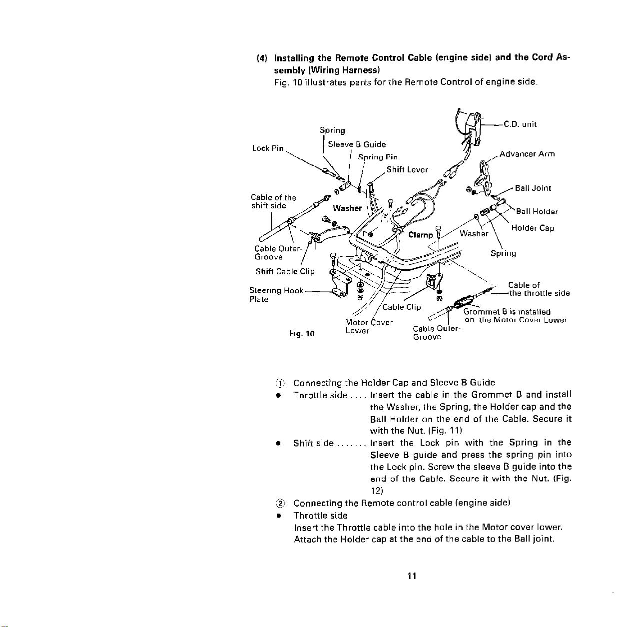
Installing the Remote Control Cable (engine side) and the Cord AS-
14)
sembly (Wiring Harness)
Fig. 10 illustrates parts for the Remote Control of engine side.
Spring
et 8 is installed
e Motor Cover Lower
@ Connecting the Holder Cap and Sleeve B Guide
. Throttle side Insert the cable in the Grommet B and install
the Washer, the Spring, the Holder cap and the
Ball Holder on the end of the Cable. Secure it
with the Nut. (Fig. 11)
l
Shift side .~ Insert the Lock pin with the Spring in the
Sleeve B guide and press the spring pin into
the Lock pin. Screw the sleeve B guide into the
end of the Cable. Secure it with the Nut. (Fig.
12)
@ Connecting the Remote control cable (engine side)
. Throttle side
Insert the Throttle cable into the hole in the Motor cover lower.
Attach the Holder cap at the end of the cable to the Ball joint.
11
 Loading...