

TOHATSU 115 Owner's Manual
TOHATSU
OUTBOARDS
No.00311050-O

Copyright © 2007 Tohatsu Corporation. All rights reserved. No part
of this manual may be reproduced or transmitted in any form or by
any means without the express written permission of Tohatsu
Corporation.

.,;c, ,.:i
i . . pi ,, ,. .,,
i ,... _,,,, ,~,.,.~.., ,~ ,,A ,~,
TOHATSU ENGINE
OWNER REGISTRATION AND INDENTIFICATION
Upon purchasing this product, be sure your dealer fills out the WARRANTY
CARD correctly and mails it to the distributor. completely fdled in. This card
identlfles you as the legal owner of the product and serves as your warranty
registration of the same.
If this procedure is not followed, your outbord will not be covered by warranty.
PREDELIVERY CHECK
Be sure that the product has been checked by an authorized TOHATSU dealer
before the delivery.
Warranty
This Tohatsu product is fully guaranteed against defective materials and
workmanship for the period from the date of purchase. provided that the
purchase has been registered in accordance with the above.
The warranty will not apply to normal worn parts, adjustments, tune-ups or to
any damage caused by:
1) Uses or operations NOT conforming to the instructions described in this
cwnm manual;
2) Participating in or preparing for racing or other competitive activity;
3) Water entering the engine or the engine room,
4) Any other thoughtless use or operation
The warranty will become void if the product has been altered, modified or
repaired by any other than a company or a service firm authorized by
TOHATSU.
The warranty will cover only your TOHATSU product and will not cover the
boat mounted with the product, trailer, equipment or accessories associated to
the product.
Serial Number
Please record the serial number of the engine (indicated on the lower engine
ccwer and cylinder block) in the space below. This number will come in handy
in the event of theft or to quickly help identify the product type.
Serial Number :
TOHATSU ENGINE
To you the Customer
Thank you for selecting a Tohatsu product. You are now the proud owner of an
excellent outboard engine, which will serve you for many years to come.
We would like to point out that carefree usage can only be assured on the
condition that this manual is read through in its entirely and maintenance
routines. as described later in this manual. are followed carefully. Should
difficulty arise with the engine, please check the trouble according to the
troubleshooting list at the end of this manual. and if it can not be remedied.
contact an authorized Tohatsu service shop or your dealer.
We hope you will get much enjoyment from this product and wish you good
luck with your boating adventures.
Tohatsu Corporation
NOTICE
HEED ALL WARNINGS AND CAUTIONS AS SET FORTH HEREIN.
THEY HAVE BEEN INCLUDED FOR YOUR SAFETY AND MUST BE
READ CAREFULLY NEGLIGENCE IN OBSERVING SUCH WARNINGS
AND CAUTIONS COULD RESULT IN SEVERE INJURY OR DEATH.
EMERGENCY STOP SWITCH
The stop switch will cut off the engine when the stop switch line is pulled out.
This line connects to the wrist of the operator, effectively preventing injuries
from the propeller in case he fallen overboad. We highly recommend use of the
stop switch line. since it can save the life of the operator if bad things come to
wane. However, we would also like to point out the drawbacks of the switch to
the operator. Accidental activation of the switch (such as the line being pulled
in heavy seas), could cause passengers to lose their balance, fall overboard, and
could result in loss of power in heavy seas. strong currents or high winds. Loss
of control while mooring is another potential hazards
To prevent such hazardous situation. the line is curled and will extend to a full
1,300mm.
WARNING
As the operator/driver of the boat, you are responsible for the safety of those
aboard, other crafts around you and that local boating regulations are followed.
As such you should possess thorough knowledge of correct operation of the
boat, its accessories and the engine. Thus, to learn about correct operation and
maintenance of the engine, please read through this manual carefully.
TOHATSU ENGINE
WARNING
It is very difficult for a person standing or floating in the water to take evasive
action should he see a power boat heading in his direction, even at a slow
speed. Therefore. it is strongly recommended that when your boat is in the
immediate vicmity of people in the water, the engme be shifted to neutral and
shut off.
SERIOUS INJURY IS LIKELY IF CONTACT IS MADE WITH A PERSON
IN THE WATER BY A MOVING BOAT, GEAR HOUSING, PROPELLER,
OR ANY SOLID DEVICE RIGIDLY ATTACHED TO A BOAT OR
GEARHOUSING.
It is the operator’s responsibility to perform all safety checks and to ensure that
all lubricatmn and maimenance instructions are complied with for safe
operation It is also the operator’s responsibility to return the unit to the local
dealer for periodic inspection.
Correct periodic maintenance and good care of this outboard engine will lessen
the chance for problems and keep overall operating expenses at a minimum.
SERVICING, REPLACEMENT PARTS & LUBRICANTS
Only let an authorized TOHATSU service shop perform servicing or maintenance on this product. Be sure to use genuine parts, and genuine lubricants or
recommended Iubricantx
MAINTENANCE
As the owner of this outboard engine. you should have acquanted yourself with
the correcr maintenance of the same. Please comply with all instructions on
lubrication and maintenance. and return the engme to the dealer for periodic
inspection at the prescribed intervals.
Troublefree operation cannot be expected unless the engine receive conect
periodic maintenance and is taken good care of. Moreover, if such maintenance
is performed periodically. it is not likely that a costly overhaul would ever be
required.
USE OF SERVICE SHOP
When subjecting your TOHATSU product to a check or a repair, please be sure
to use a TOHATSU dealer authorized by the TOHATSU or a TOHATSU agent.
CONTENTS
SPECIFICATIONS ..........................................
Page
.,g
NOMENCLATURE
......................................... -9
1. ENGINE INSTALLATION ON BOAT~--~~~..~~~~.--~~~~I o
2. REMOTE CONTROL BOX
q
Installing the Remote Control Box ...........................
H Connecting the Remote Control Cable to the Remote Control Box
q
Connecting the Remote Control Cable to the Engine
q
Connecting Cords and Cables
3. TRIM ADJUSTMENT
q proper Trim Angle
~lmproperTrimAngle(bowrisestoohigh).~~.--~~~~~~~~~.-~~~~~2 3
q
ImproperTrim Angle (bow dips into the water)
4. MULTI-PURPOSE METER. ...........................
.................................. -22
....................................... .23
5. INSTALLING THE DRAG LINK ASSEMBLY
6. BATTERY
, F,,,== & ENGINE OIL
.
8. Running
............................................. .28
..................................
................................................
............................ .,4
‘14
.. .15
............ .17
............................ ...2 0
................ “23
.24
....... ...2 7
.2g
32
q Break-in
gStafiing
q
Manual Start-in case of trouble with the electric starter motor
q Wam.up ..............................................
CJ. WARNING SYSTEM ...................................
................................................ .32
..............................................
...3 3
...... .36
.3*
.-,9
10. OPERATION OF THE REMOTE CONTROL BOX.....4 1
11. MOORING WITH THE ENGINETILTED
12. DISMOUNTING THE ENGINE FROM THE BOAT
UP...........4 4
. ...4 6
13. ADJUSTMENTS.. _. . -4,
p Remote contra, Lever Load I.. , .4,
q Trim Tab Adjustment I.. . -. .47
14. INSPECTION AND MAINTENANCE ...............----4a
n Dally ,nspection , . . .48
q Periodic [nspection Checklist -. -. -. .53
q Cha”gingGearOil ~........,-~............-..............-~~
q Cleaning Tanks and the Filten ... -55
H Checking and Refilling Oil in the Power Trim &Tilt Unit. . 37
,(j. W,NT,=R STORAGE.. . =,a
16. PRE-SEASON CHECK.. _. -60
17. CHECKING AFTER STRIKING UNDERWATER
OBJECT. . .62
18. IF THE ENGINE BECOMES SUBMERGED
IN WATER.. _. _.
19. PRECAUTIONS IN COLD WEATHER ....“--........63
20. TR(-,,,BLES,,(-,OTlNG , . _. _. _. _. .63
_. -62
2,. ,.,CCESS,-,R\ES
22. OPTIONAL ACCESSORlES _. _. .&j
23. PROPELLER S,==ECTlON
24,
W,R,NG DIAGRAM... . . . . ._.._... . . . . . . . . . . . . . ,.-by
. _. 1. _. -65
. _. ._. . .._. . . . . .68
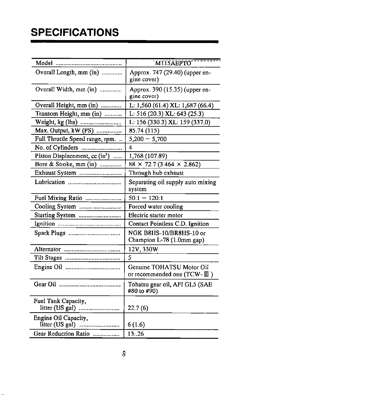
SPECIFICATIONS
Overall Width, mm (in) ._,._,,_,____.
Overall Height, mm (in) .,.,,.,___,,_
Transom Height, mm (in) .._._...
Weight, kg (lbs) . . .._.._.__._._.._......, L: 156 (330.3) XL: 159 (337.0)
Max. Output, kW (FS) ._.........._...
Full Throttle Speed range, ‘pm. _.
No. of Cylinders .,._...._.,_.__._.__..,... 4
Piston Displacement, cc (in’) ..___.
Bore & Stroke, mm (in) _,__,_,,___,__
Exhaust System _...._...._.__.____,.,.....
Lubrication . . . . . . . . . . . . . . . . . . . . .
Fuel Mixing Ratio ._....._._....__.._....
Cooling System _...._..........__.........
Starting System .._.._.__....._.........
Ignition
Spark Plugs ._...._.........._...............
Alternator .._........._....__.......,....,,.,. 12V, 330W
Tilt Stages
Engine Oil _,_......._,.,,_,__,....,.,,..,,,.,
Gear Oil
. . . .._._.._......._....................
. .._._...............
. . . . . . . . . . . . . . . . . . . . . . . . . . . . . . . .
Approx. 390 (15.35) (upper engine cover)
L: 1,560 (61.4) XL: 1,687 (66.4)
L: 516 (20.3) XL: 643 (25.3)
85.74 (115)
5,200 - 5,700
1,768 (107.89)
88 X 72.7 (3.464 X 2.862)
Through hub exhaust
Separating oil supply auto mixing
svstem
5O:l - 12O:l
Forced water cooling
Electric starter motor
Contact Pointless CD. Ignition
NGK B8HS-lO/BR8HS-10 or
Chamoion L-78 fl.Omm eauj
5
Genuine TOHATSU Motor Oil
or recommended one (TCW- Ill )
Tohatsu gear oil, API GL5 (SAE
#80 to #90)
Fuel Tank Capacity,
litter rUS eal) . . . .._...._..............
Engine Oil Capacity,
litter (US gal) . .._....___..........
Gear Reduction Ratio .._._.._.__,_,.__
22.7 161
6 (1.6)
13:.26
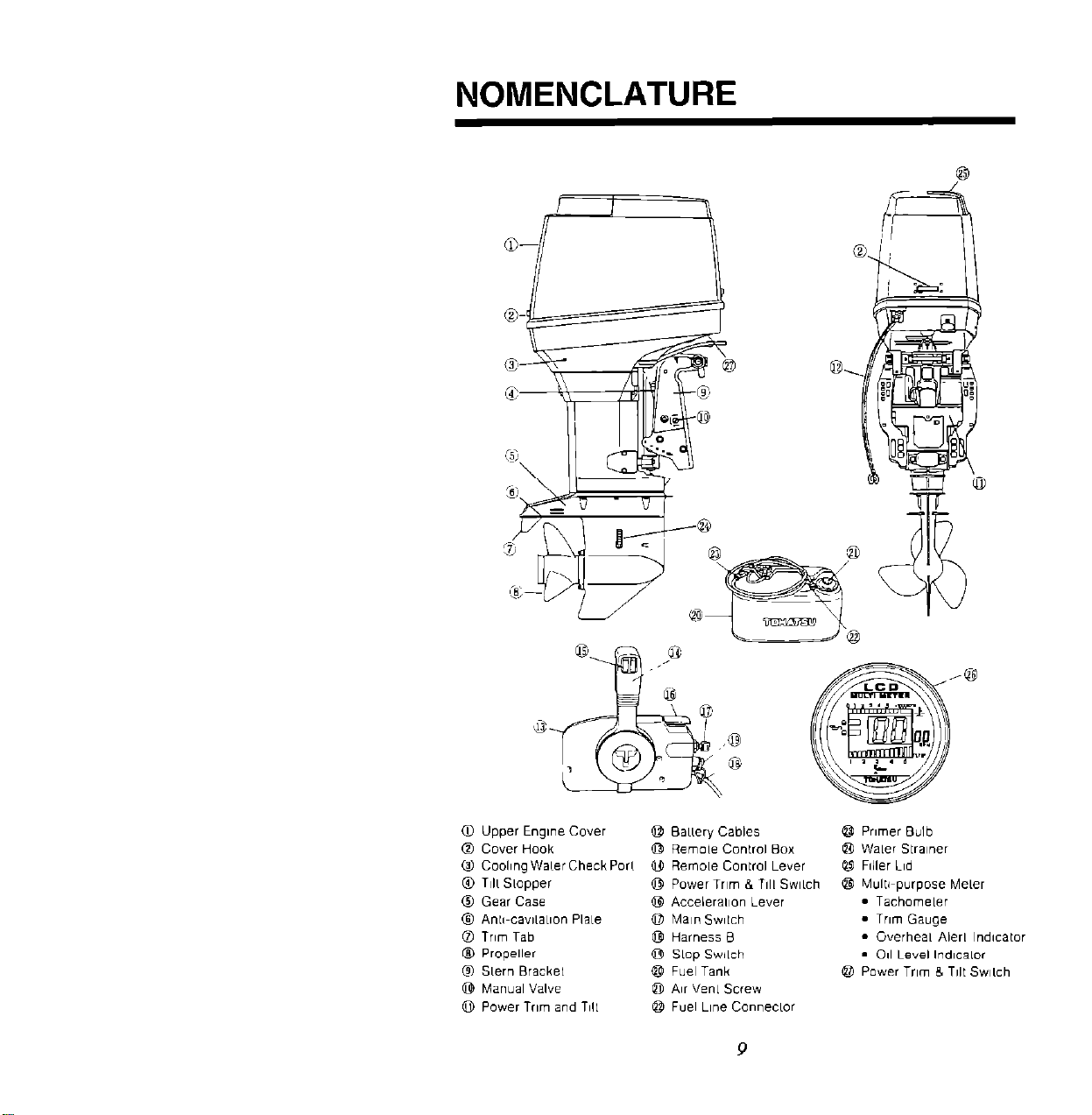
NOMENCLATURE
1. ENGINE INSTALLATION ON BOAT
Most boats are rated and certified in terms of their maximum
horsepower limit, and this is shown on the boat’s certification plate. Do
not equip your boat with an outboard that exceeds this limit. If in
doubt, contact your dealer.
Do not operate the engine until it has been securely mounted on the
boat in accordance with the instruction below.
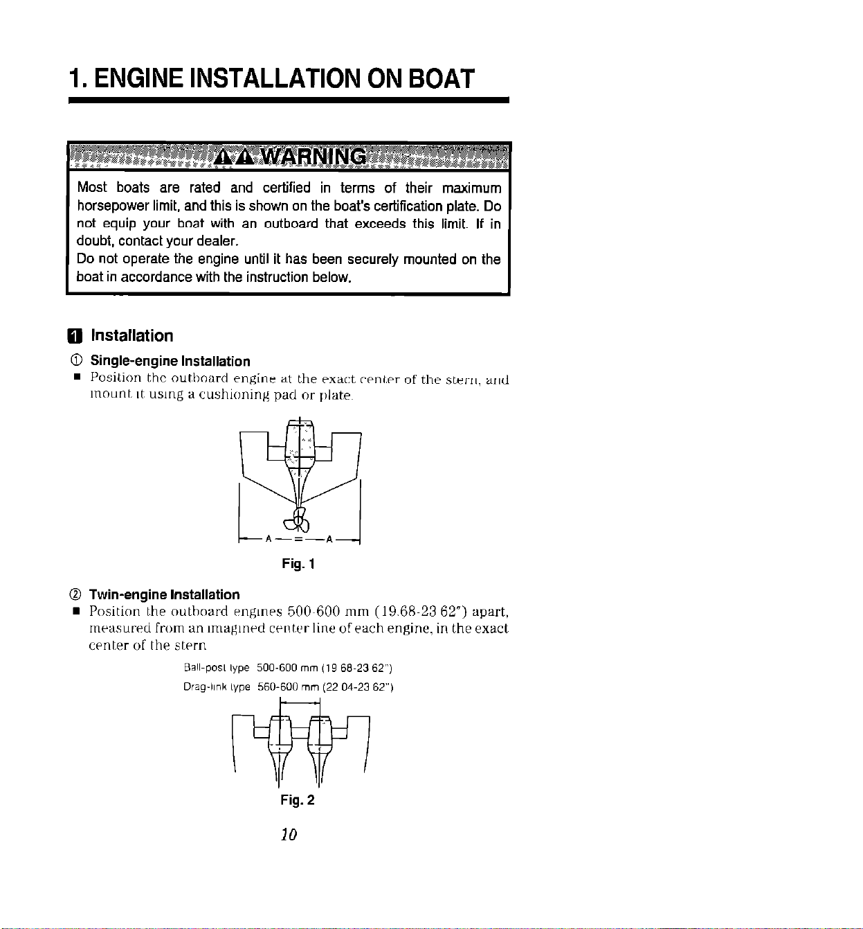
m Installation
0 Single-engine Installation
n
Position t,he out~lmard engine at the rxact, CP~I,W of the stern, and
mount, it, usmg a cushioning pad or plak
Fig. 1
0 Twin-engine Installation
n
Position t,he outhoard mgm?s 500~600 mm (19.68-23 62”) apart,
rnrasurrd from an mlagmrd crnkr line ofeach engine, in the exact
cpntkr of the stkrn
Fig. 2
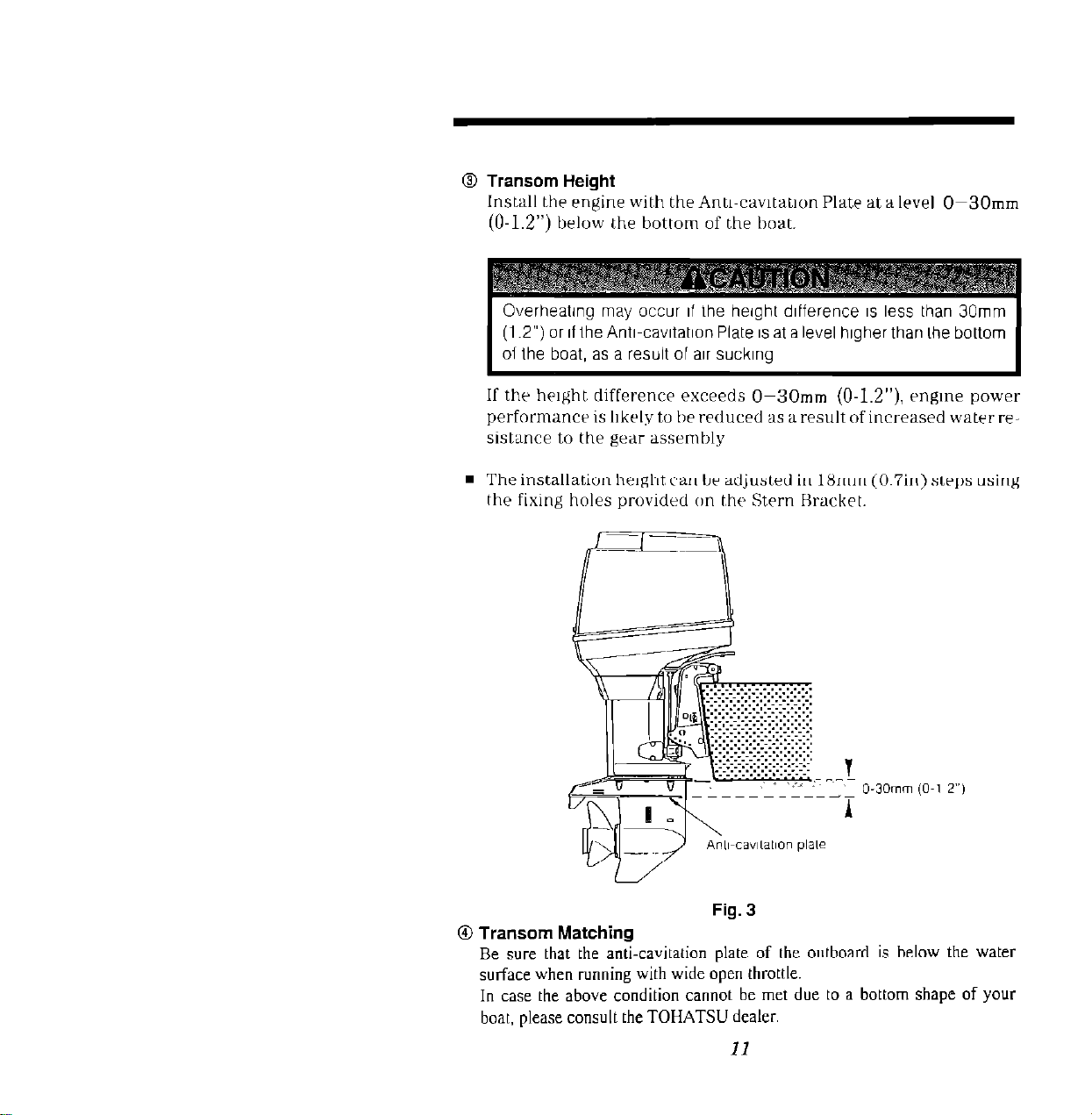
0 Transom Height
Install the ent+$ne
(o-1.2”)
Overheating may occur II the height dltference IS less than 30mm
(1.2”) or If the AntWcawtatlon Plate IS at a level higher than the bottom
of the boat, as a result of air sucking
I
If thr height, difference exceeds O-30mm (O-1.2”), rnglne power
performancr is hkely t,o be reduced as a result of increased water resistance to the gear assembly
. The installat,ion height, can be adjusted in 18mm (0~7in) st?ps using
the fixing holes provided rrn t,he St,ern Hracket.
below the bottom of the boat.
wit,h
the Antl~cawtatlon PIat,? at a level O-30mm
I
-3omm (0 -1 2-i
Fig. 3
0 Transom Matching
Be sure that the anti-cavitation plate of the outboard is below the water
surface when running with wide open throttle.
In case the above condition cannot be met due to a bottom shape of your
boat, please consult the TOHATSU dealer.
11

1. ENGINE INSTALLATION ON BOAT
0 Attaching the Stern Bracket
Aft,er posit,ioning the St,ern Hrackrt. fixthe engine temporarily to the
transom wth b&s (10XWmm, pitch 1.5mm) foreasyattachment.
Bolts are not, included wth the accessones.
Ihll 4 holes in t,he t,ransom board, matching the holes in the Stern
Bracket, and t,hen secure the rngme with the supplied bolts
(Ml%XWmm) and nut,s. He sure to use the washers. The small-diameter washers go w1t.h t,he bolts and the larger diameter washers
go wit,h t.he nuts
The mounting holes may be drilled beforehand by referring to the
dimenslonal drawing below.
Fig. 4
1. We recommend thut the bolt head ofat
inward while the nuts we kept on the outside of the boat to p-e-
2. lkmporady used bolts (10~6Omm) should be removed
the Stem Brackets has bee-n mmerlu installed.
12
least
the upper boltsface
after
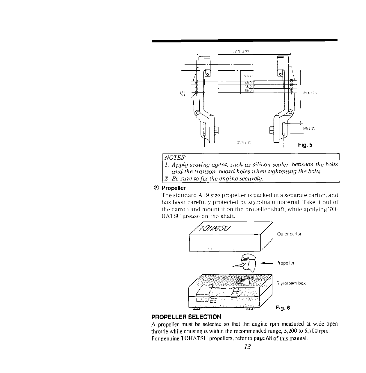
Fig. 6
PROPELLER SELECTION
A propeller must be selected so that the engine rpm measured at wide open
throttle while cruising is within the recommended range. 5,200 to 5.700 rpm.
For genuine TOHATSU propellers, refer to page 68 of this manual.
13
2. REMOTE CONTROL BOX (model RC5E)
The following explains inst,allat,ion for right~hand driving.
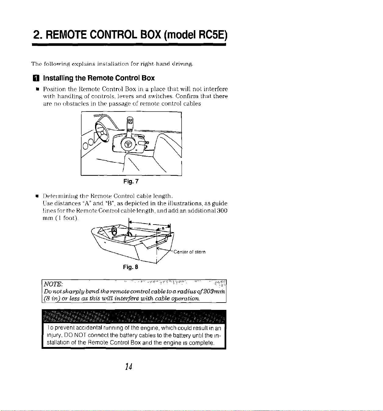
m Installing the Remote Control Box
n
Position the Kernote Control Box in a place that will not interfere
with handling of controls, levers and switches. Confirm that there
are nc obstacles in the passage of remote control cables
Fig. 7
n
Determining the Kernok Control cable length:
Use distances “A” and “B”, as depicted in the illustrations, as guide
lines for the Kemot,e Control cable length, and add an additional 300
mm (1 foot)~
Fig. B
To prevent accidental running of the engine, which could result in an
injury. DO NOT connect the battery cables to the battery until the in-
stallatlon of the Remote Control Box and the enaine
I
IS comolete.
14
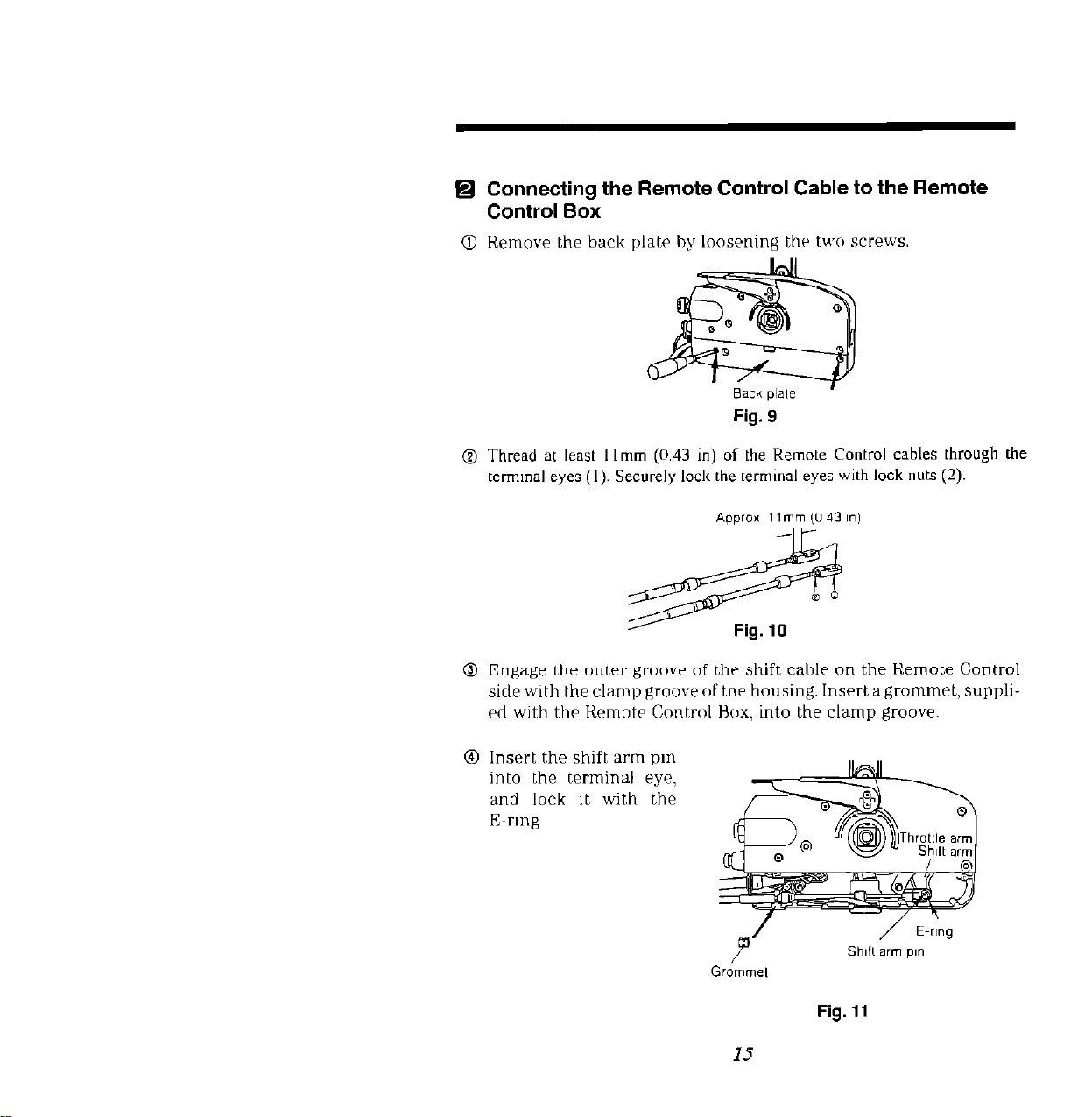
H Connecting the Remote Control Cable to the Remote
Control Box
0 Remove the back plat,e hy loosening thr t,wo screws.
Fig. 9
0 Thread at least I Imm (0.43 in) of the Remote Control cables through the
termmal eyes (I). Securely lock the terminal eyes with lock nutS (2).
@ Engage the outer groove of t,he shift cable on the Remote Control
side with the clamp groove of t,hr housing. Insert a grommet, supplied with the Remote Cont,rol Hex, into the clamp groove.
@ Insert the shift arm pm
into the terminal eye,
and lock It wit,h the
E~rlng
Fig. 11
15
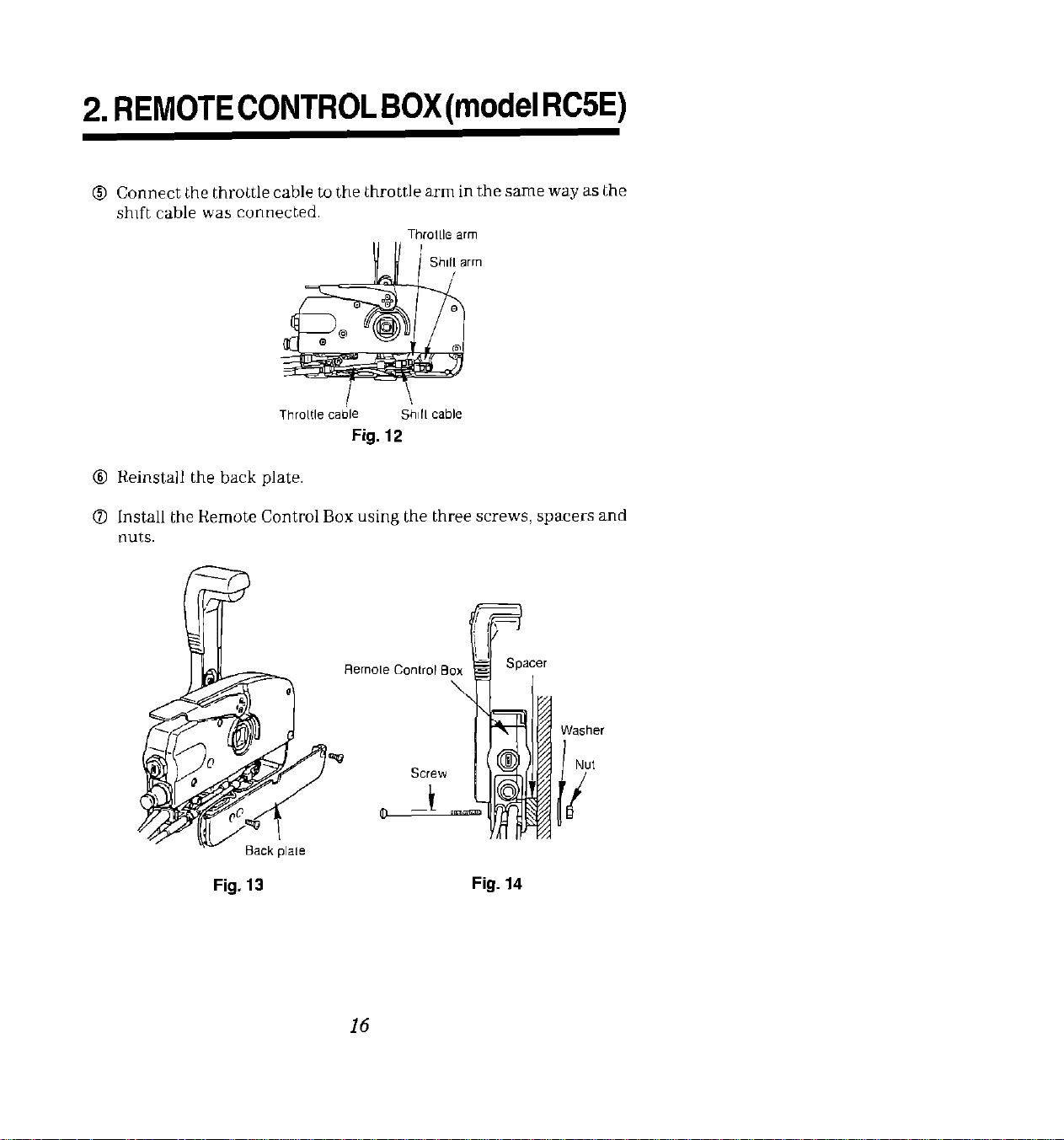
2. REMOTECONTROLBOX(model RC5E)
0 Connect the throttle cable to the throttle arm in the same way as the
shift cable was connected.
Throllle arrr
ShlII cable
Fig. 12
@I Reinstall the back plate.
0 Install the Remote Control Box using the three screws, spacers and
nuts.
Fig. 13
Fig. 14
16
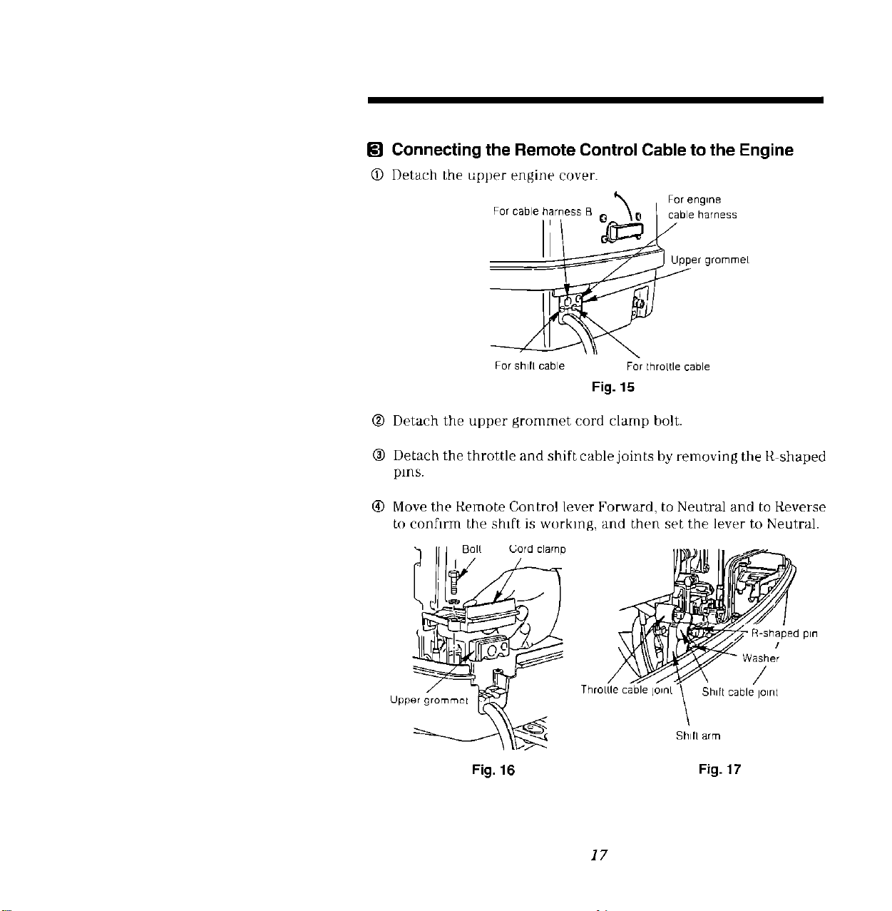
H Connecting the Remote Control Cable to the Engine
0 Detach the upper engine cwer
For lhroltle cable
Fig. 15
0 Detach the upper grommet cord clamp bolt.
@ Detach the throttle and shift cable joints by removing the K-shaped
pins.
@ Move
t,he Kemot,e Cont,rol lever Forward, to Neutral and to l&verse
to confrm the shift is wurkmg, and then set the lever t,o Neutral.
Fig. 16
Fig. 17
17
2. REMOTE CONTROL BOX(model RGE)
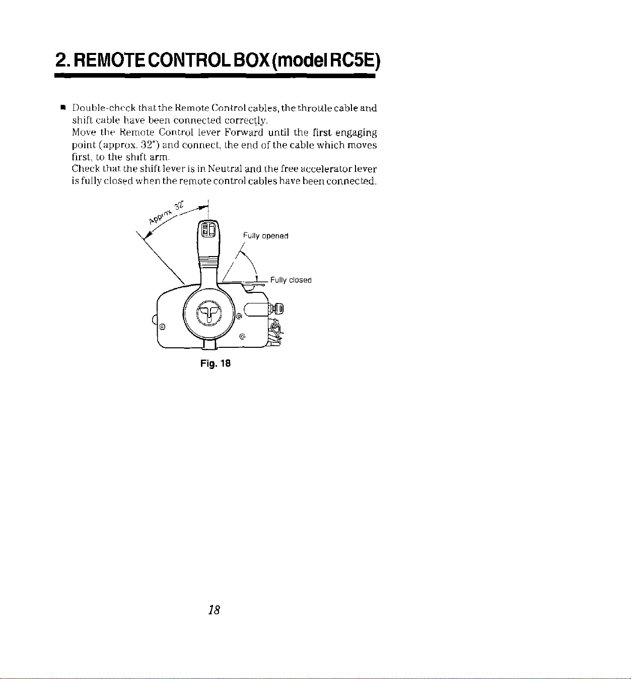
n
Double~check that the Kemot,e Control cables, the throttle cable and
shift cable have been connected correctly.
Move thr Remote Control lever Forward until the first engaging
point (approx. 32~) and connect, the end of the cable which moves
first, to the shift arm.
Check that. the shift lever is in Neutral and t.he free accelerator lever
is fully closed when the remote control cables have been connected.
Fig. 18
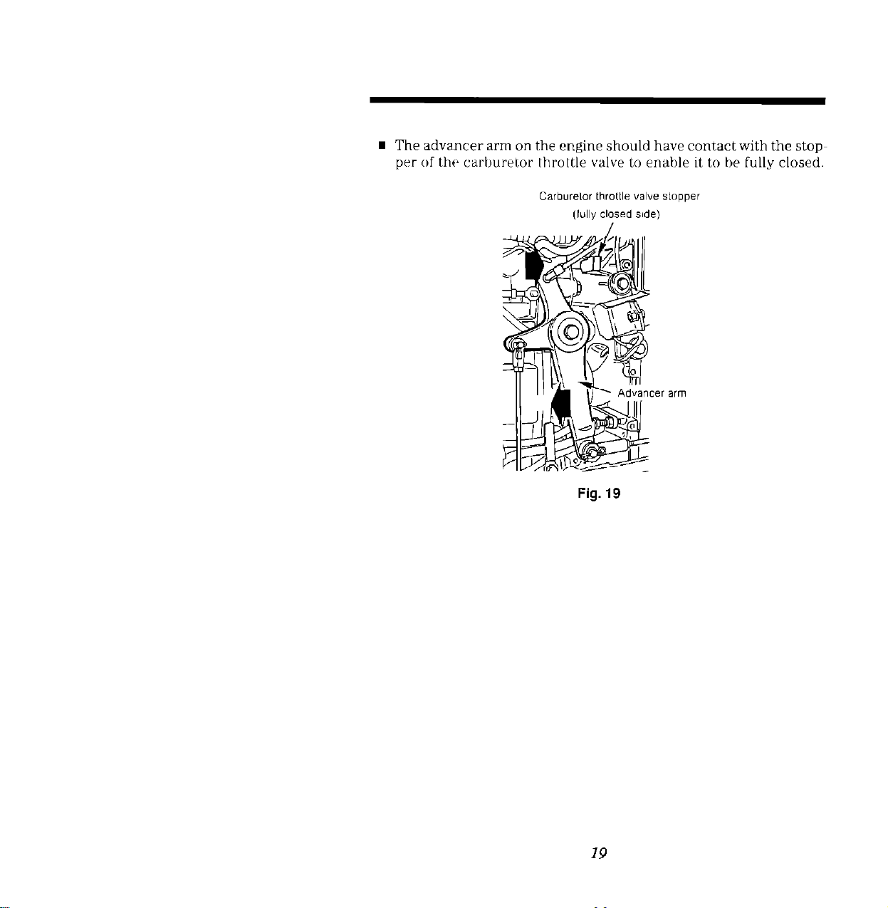
n
The advancer arm on t,he engine should have contact with the stopper of t,hr, carburetor throttle valve to enable it to be fully closed.
arm
Fig. 19
19
2. REMOTE CONTROL BOX(model RC5E)
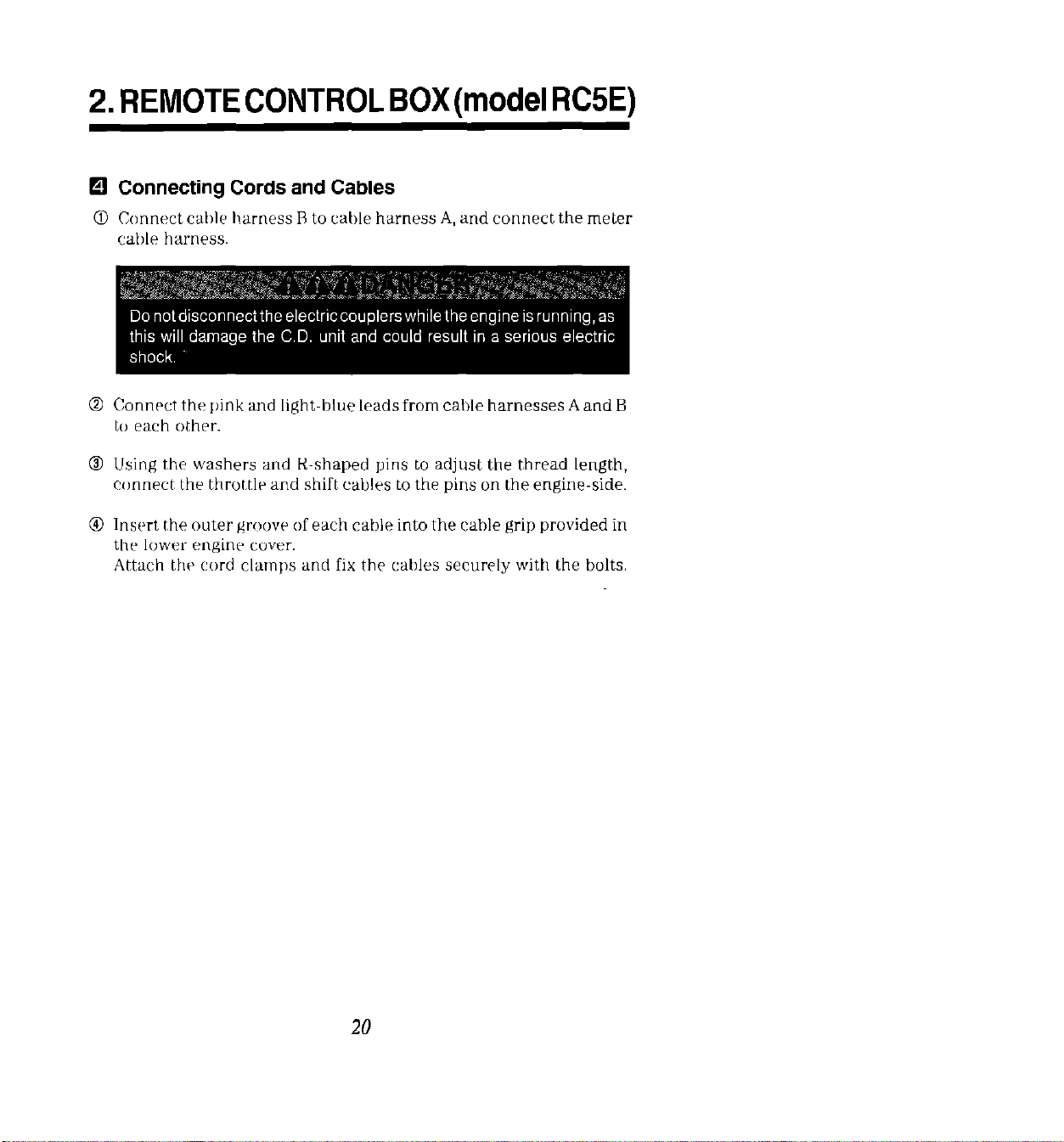
fl Connecting Cords and Cables
0 Connect cable harness R to cable harness A, and connect the meter
catk harness.
0 Connect the pink and light~blue leads from cat& harnesses A and B
to each other.
0 Using t,he washers and t&shaped pins to adjust the t,hread length,
cunnfxT the throt,t,lr and shift, cables to the pins on t,he engine-side.
@ lnwrt, t,he outer ~roow of each cable into the cable grip provided in
the lower engine cover.
At,tach t,tw cord clamps and fix the cables securely with the bolts.
20
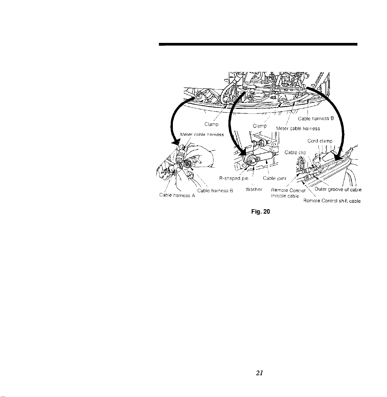
Fig. 20
21
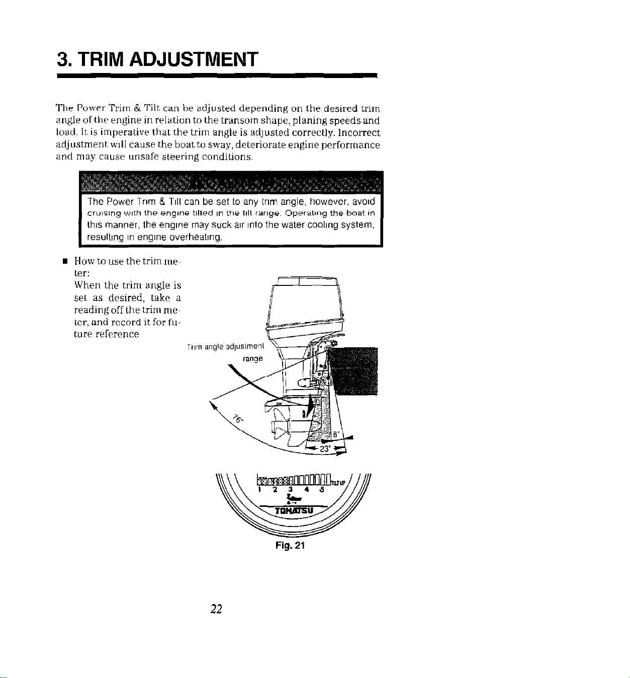
3. TRIM ADJUSTMENT
The Power Trim & Tilt can
angle of
load.
adjustment
t,h?
engine in relation to the transom shape, planing speeds and
It, is imperative that, the
wll cause the boat to sway, deteriorate engine performance
he
adjust,ed depending on the desired trim
trim
angle is adjusted correctly. Incorrect
and may cause unsafe steering conditions.
The Power Trim & Tilt can be set to any trim angle, however. avold
cruising with the engine tilted III the tilt range. Operating the boat in
this manner, the engine may suck air into the water cooling system,
resulting in engine overheating.
n
How to use the trim mew
ter:
When the trim angle is
set as desired, take a
reading off the trim meter,
and record
it for fu-
ture reference
22
Fig. 21
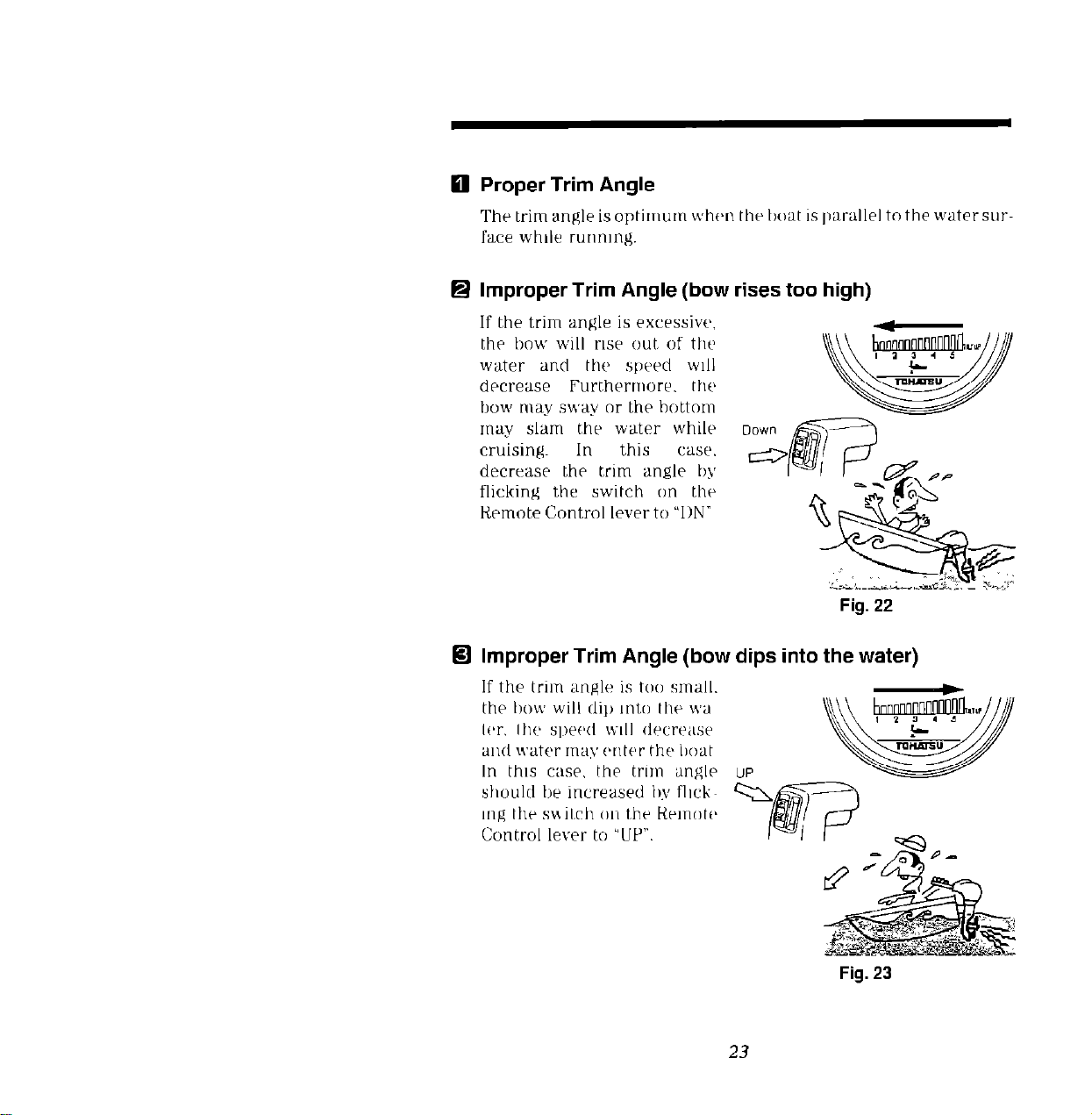
Improper Trim Angle (bow rises too high)
If the trim angle is excessive.
thr t,ou will r,se out of the
water and the sperd Will
drcrease Furt,herrrwre. the
bow may sway or the hottom
may slam t,hr water while
crusing In this case.
decrrasr th? t,rim angle t)>
flicking t,he switch rrn thr
KPmote Control lever to “1)N”
Fig. 22
Improper Trim Angle (bow dips into the water)
23
Fig. 23
 Loading...