

Toggle TOGL2448EL, TOGL2460EL, TOGL2472EL, TOGL3060EL, TOGL3072EL Assembly Instructions Manual
...Page 1
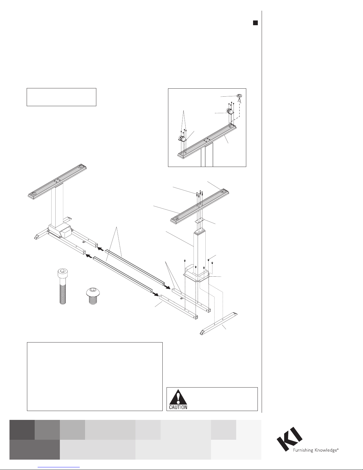
Assembly Instructions
Figure 1
Toggle® Tables
Dual Motor Height Adjustable Base, Model EL
Motor-Operated Furnishing
-FOR COMMERICAL USE ONLY-
M6 x 35
socket head
cap screw
M8 x 12
button-head
machine screw
leg-to-leg
spanners
M6 x 35
socket head
cap screw
foot
leg
column
set screw
holes
cross-support
tube
#10-24 x /
Torx head
screws
Detail A
3
"
8
non-locking
locking
caster
adjustable
caster
glide
April 2017
adjustable
glide
foot
plate
button-head
machine screw
motor housing
end-support
foot
M8 x 12
mounting
flange of
tube
1. Carefully remove contents from
packaging, set out on a soft, clean
surface and refer to Figure 1
to identify the parts required for
assembly.
2. Position two cross-support tubes
(with mounting tabs down and
facing inward), and one
end-support tube out as illustrated.
Place a leg column assembly over
the three tubes, aligning all six
mounting holes on the flange of the
column with the mounting holes on
the three tubes. Using six
M8 x 12 button head machine
screws torqued to 9.5 ft/lbs, secure
the flange of the leg column to the
three base tubes (Figure 1).
3. Mount the foot to the leg column
by first positioning a plastic foot
plate over the mounting location
on the leg column. The plastic foot
plate should be oriented so the
raised flange faces down on the
leg to nest the foot plate in place.
Position a foot over the flat face
of the foot plate, aligning holes
in underside of the foot with the
mounting holes in the column, and
secure foot to column with four
M6 x 35 socket head cap screws.
Torque to 7.5 ft/lbs (Figure 1).
4. If casters are required, twist both
adjustable glides out of the foot.
Locking and non-locking casters
are supplied. Locking casters
should be located toward the
front, user side of the table for
easy access while the non-locking
casters are located to the back.
Using four #10-24 x 3/8” Torx
screws, carefully secure the casters
to the foot (Detail A).
ATTENTION: Following assembly, table must be “zero set”
prior to being placed into service. Failure to do so can cause
table to malfunction.
Table “Zero Setting”: Press and hold the Up button for
two seconds then release. Next, press and hold the Down
button until table has reached its lowest position then release
Down button. Then, press the Down button again and hold for
approximately 10 seconds. The table now re-set at its “Zero
Setting” position and is ready to operate.
Assemble units as described herein only. To do otherwise
may result in instability. All screws, nuts and bolts must be
tightened securely and must be checked periodically after
assembly. Failure to assemble properly, or to secure parts
may result in assembly failure and personal injury.
5. Repeat steps 2 & 3 for second leg
assembly and step 4 if casters are
required (Figure 1).
6. Position two leg-to-leg spanners
with channel opening face up, then
slide both spanners into the open
ends of each base tube of both base
assemblies. Slide bases together,
but do not secure with set screws at
this time (Figure 1).
Page 2

Toggle® Tables - Dual Motor Height Adjustable Base, Model EL
pan head screws
pan head screws
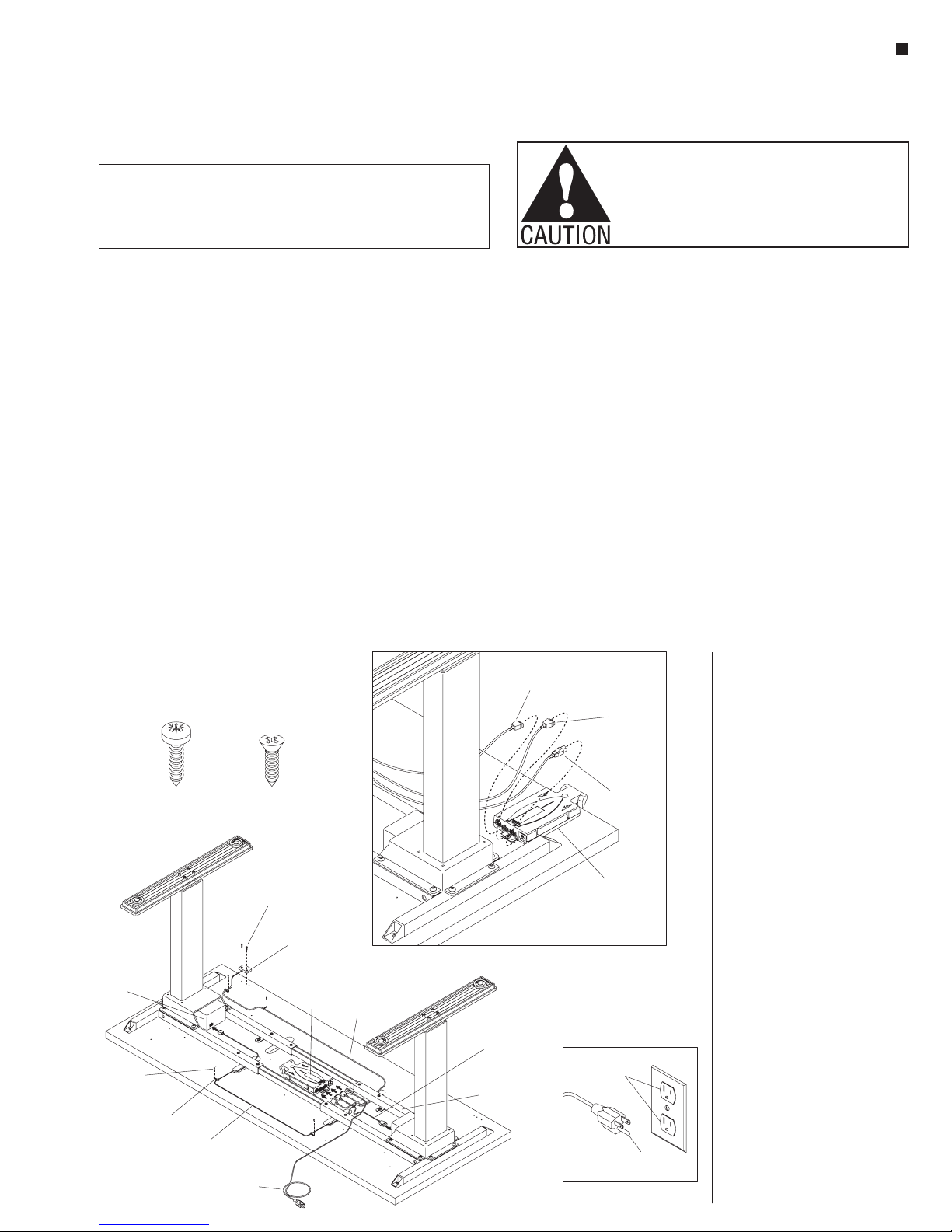
Figure 3 - 30 & 36 Table Depth
””
control
Assembly Instructions
7. Carefully turn table top upside
down on a soft protective surface
and set the base assembly onto
the underside of the top. Position
one base end, so base mounting
holes align with table top
mounting holes, and secure base
to top using four M5.5 x 22 pan
head screws. Slide the other base
end into position to align base
mounting holes to the table top
holes and secure with four
M5.5 x 22 pan head screws.
Insert and tighten eight M10 x 25
set screws as illustrated, through
the cross support tubes and
down to the leg-to-leg spanners.
Torque to 4.5 ft/lbs to secure
(Figure 2).
8. For 24” deep tables, the control
box must be mounted to the
underside of the table top
centered between the cross-tube
assemblies. Position the control
box over the pre-drilled mounting
holes and secure using two
M5.5 x 22 pan head screws
(Figure 2).
Assemble units as described herein only. To do otherwise
may result in instability. All screws, nuts and bolts must be
tightened securely and must be checked periodically after
assembly. Failure to assemble properly, or to secure parts
may result in assembly failure and personal injury.
M5.5 x 22
table top
M10 x 25
set screws
(24 deep)"
Figure 2 - 24 Table Depth”
CAUTION: If Channels (Wire Troughs) are used they are not to be used for routing
extension cords. Power supply cords are not to be routed across or through more
than one complete unit/worksurface.
M5.5 x 22
pan head screws
M10 x 25
set screws
M5.5 x 22
pan head
screws
control
box
leg-to-leg
spanner
9. For 30” & 36” deep tables, the
control box may be mounted
to the underside of the table
top, either at the center of the
top between the cross-tube
assemblies (Figure 2), one of
two locations near the front of
the table (Figure 3), or centered
behind the cross-tube assemblies
(Figure 7). If using one of the two
front locations, the built in switch
on the control box will eliminate
the requirement for the key pad
(Figure 3).
2
M5.5 x 22
M10 x 25
set screws
M5.5 x 22
pan head
screws
table top
(30 or 36 deep)””
M10 x 25
set screws
cross-tube
assembly
M5.5 x 22
pan head screws
box
Page 3
Toggle Tables - Electric Base
Assembly Instructions
Table Wiring
Note: Control cables can be routed
differently than shown. Illustration is for
reference only (Figure 3).
Note: When plugging leg control cord
ends in, make sure to push in straight to
avoid bending any pins in the electrical
control box or leg motor. The plug will
click when it is locked into place.
Note: If plug needs to be removed,
make sure power cord is un-plugged
from power source outlet first. Then
push down on release tab on the
control cable plug while simultaneously
pulling on the end to remove from the
socket.
1. : Plug the longer legLong Leg Cord
control cord into outer most hole
labeled “1” on control box. ThenLA
route cord to leg farthest from control
box. Use cut outs in table to route under
cross tubes. Plug other end into open
hole on leg motor (Figure 3).
2. The next hole toShort Leg Cord:
the right on the control box will be
utilized by the shorter leg control
cord. Plug short leg cord into control
box at the hole labeled “2” andLA
route to the leg motor socket that is
closest to the control box. Use cut
outs in table to route under the cross
tubes. Plug other end into open hole
on leg motor
(Figure 3).
3. The key pad can beKey Pad:
mounted in two locations. Both
locations are on the front side of
table top and opposite of electronic
control box (Figure 3). Using pre-
drilled holes, secure key pad to table
top with
M4.2 x 19 flat head screws. Once
key pad is mounted, route attached
cord to control box. Use Figure 3 for
cord routing reference and for the
optimal usage of zip tie points. Once
the key pad cord is routed to control
box, plug cord into the smallest hole
on box labeled “”(Figure 3).RC
Note: Make sure all cables are routed
correctly and plugged into correct
holes on control box and leg motor
locations before installing zip-ties.
4. Zip-ties: Included are four zip-ties
for use to keep cords tight to table.
Using Figure 3 for reference, wrap
the zip ties around the loose cords
and then mount the zip-tie to the
table top with a M5.5 x 22 pan head
screw into the pre-drilled holes. The
zip-ties have a built in mounting hole
which has to lay flat onto surface.
Make sure zip-ties and cables are
snug before moving to next step
5. The final cordPower Cord:
installed is the power cord. Plug
power cord into remaining open hole
which is elevated higher on the
control box then the rest. This hole is
labeled “ 110-120V”. Cord shouldAC
not be zip-tied or routed through cut
outs on table (Figure 3). Do not plug
in into power source at this time.
6. With two people, carefully turn
table to the upright position. Adjust
glides on feet to get table level. Plug
Power cord into power source and
test the height adjustable table. If
table is experiencing issues see the
trouble shooting guide in this
instruction.
Detail
GROUNDING INSTRUCTIONS
This product is for use on a nominal 120-volt circuit and has a grounding plug
that looks like the plug illustrated in Detail C. Make sure that the product is
connected to an outlet having the same configuration as the plug. No adapter
should be used with this product.
Table Wiring
Note: Control cables can be routed
differently than shown. 24” deep
tables must have the control box
mounted between the cross-tube
assemblies, which requires
installation of the “optional key pad”
(Figure 4). All 30” & 36” tables may
have the control box mounted either
between the cross-tube assemblies,
at one of the two locations behind
the cross-tube assemblies or one of
two locations at the front of the table
(Detail A). Mounting to the front of
the table does not require the use
of the “optional key pad”. Follow
directions appropriate to control box
mounting location.
Note: When plugging leg control
cord ends in, make sure to push in
straight to avoid bending any pins
in the electrical control box or leg
motor. The plug will click when it is
locked into place.
M5.5 x 22
pan head screws
leg motor
M5.5 x 22
pan head screws
(six)
zip-ties
(six)
leg control cord
(long)
Figure 4
M4.2 x 19
flat head screw
M4.2 x 19
flat head screw
(max torque is 1.5 ft/lbs)
key pad
(optional)
control
box
power
cord
Toggle® Tables - Dual Motor Height Adjustable Base, Model EL
Note: If any plug needs to be
removed, make sure power cord
is un-plugged from power source
outlet first. Then push down
on release tab on the control
cable plug while simultaneously
pulling on the end to remove
from the socket.
1. Leg Cord - Long: Plug the
longer leg control cord into one
of the two rectangular sockets on
the control box, then route cord
to the leg farthest from control
box. Use cut outs in the table
to route under the cross tubes
and/or use zip ties secured with
screws at pre-drilled locations.
Plug other end of the longer leg
control cord into the open socket
on leg motor (Figure 4).
Detail B - 30 & 36 Table with Front Control Box""
key pad
cord
2. Leg Cord - Short: The next
3. Optional Key Pad: The key pad
pre-drilled holes, secure key pad
flat head screws at 1.5 ft/lbs.
leg control cord
(long)
leg control cord
(short)
cross-tube
assembly
Assemble units as described herein only. To do otherwise
may result in instability. All screws, nuts and bolts must be
tightened securely and must be checked periodically after
assembly. Failure to assemble properly, or to secure parts
may result in assembly failure and personal injury.
rectangular socket on the control
box is utilized by the shorter leg
control cord. Plug short leg cord
into control box and route to the
leg motor socket that is closest
to the control box. Use cut outs
in table to route under the cross
tubes. Plug other end of the
shorter leg control cord into open
socket on leg motor (Figure 4).
can be mounted on the front side
of table top (Figure 4). Using
to table top with two M4.2 x 19
Note: Do not overtighten screws.
Once key pad is mounted, route
attached cord to control box. Use
Figure 4 for cord routing reference
leg control cord
(short)
power
cord
control
box
grounded
outlet
grounding
C
pin
Assembly Instructions
and for the optimal usage of
zip-tie points. Once the key pad
cord is routed to control box, plug
cord into the round socket on box
(Figure 4).
Note: Make sure all cables are
routed correctly and plugged into
correct sockets on control box
and leg motor locations before
installing zip-ties.
4. Zip-ties: Six zip-ties are included
for keeping cords tight to table,
but it is not necessary to use all
six. Using Figure 4 for reference,
wrap the zip-ties around the loose
cords and then mount the zip-tie
to the table top with a M5.5 x 22
pan head screw into the
pre-drilled holes. The zip-ties
have a built in mounting hole
which must lay flat onto surface.
Make sure zip-ties and cables are
snug before moving to next step.
5. Power Cord: The final cord to
be installed is the power cord.
Plug power cord into remaining
open socket which is tri-lobe in
shape. Cord should not be
zip-tied or routed through cut outs
on table (Figure 4). Do not plug it
into power source at this time.
6. If optional wire trough was
specified for installation, go now
to page 4. If no wire trough is
specified, carefully turn table to
the upright position with the help
of another person. Adjust glides
on feet to level the table. Plug the
power cord into a grounded outlet
power source (Detail C). Note:
Power cord must have enough
slack so the table can cycle
through its entire range of motion.
7. The table must be “zero set”
prior to being placed into
service. Refer to table “zero
setting” instructions in the
trouble shooting guide on
page 6.
8. If the table is not operating
properly, see the trouble shooting
guide in this instruction.
3
Page 4
Toggle® Tables - Dual Motor Height Adjustable Base, Model EL
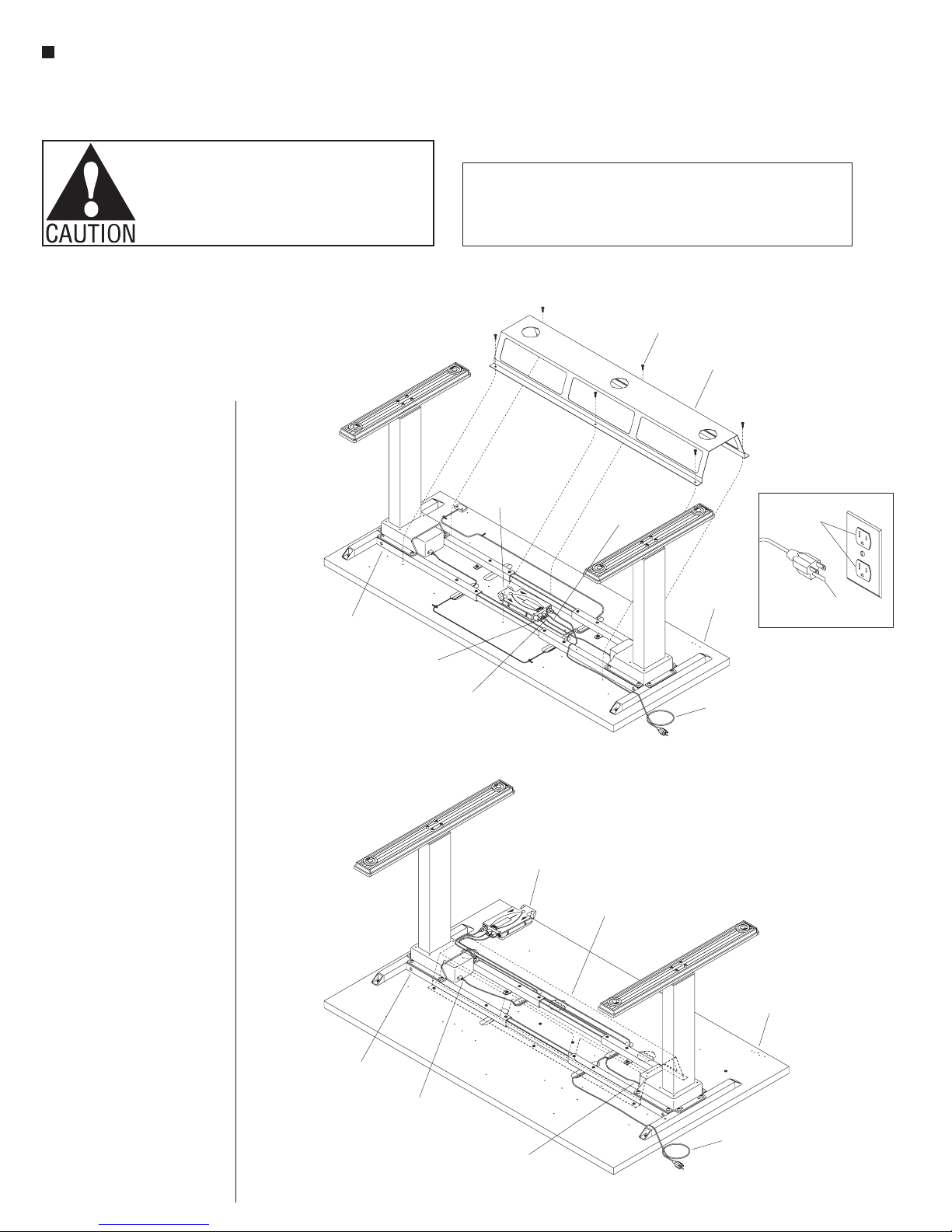
Figure 5 - Centered Wire Trough with Control Box Between Cross-Tube Assembly
Detail
Figure 6 - Centered Wire Trough with Control Box Front User Side, 30” or 36”Table Depth
Assembly Instructions
Assemble units as described herein only. To do otherwise
may result in instability. All screws, nuts and bolts must be
tightened securely and must be checked periodically after
assembly. Failure to assemble properly, or to secure parts
may result in assembly failure and personal injury.
Wire Trough (Optional)
Note: The wire trough is an
optional part that must be
ordered separately.
Note: Control cables can be
routed differently than shown.
The control box can be mounted
to the underside of table tops
24” in depth at one location,
between the cross-tube
assembly (Figure 5). Control
boxes mounting under table
tops 30” or 36” in depth can
mount in one of five mounting
locations, one being the same
as the control box mounted
between the cross-tube
assembly on 24” table tops
(Figure 5). If the control box is
mounted between the cross-tube
assembly, reference figure 5 for
placement of the wire trough.
A 30” or 36” depth table top
is the only depth which will
allow a control box to be in
the following locations. If the
control box is mounted to the
front user side of the table,
reference figure 6. Mounting
to the front of the table does
not require the use of the
“optional key pad” (Figure 6).
If the control box is mounted
behind the cross-tube assembly,
reference figure 7.
9. Align the wire trough holes to
the appropriate holes in the
table top. Using six #10 x 5/8”
pan head screws, secure the
wire trough to the table top as
illustrated (Figure 5, 6, & 7).
in the trouble shooting
guide on page 6.
12. If the table is not operating
properly, see the trouble
shooting guide in this
instruction.
cross-tube
assembly
key
pad cord
(optional)
GROUNDING INSTRUCTIONS
This product is for use on a nominal 120-volt circuit and has a grounding plug
that looks like the plug illustrated in Detail C. Make sure that the product is
connected to an outlet having the same configuration as the plug. No adapter
should be used with this product.
5
#10 x /”
8
pan head
screw
wire
trough
control
box
leg control
cord (short)
control
box
leg control
cord (long)
table top
power
cord
wire
trough
grounded
outlet
grounding
pin
C
10. With help from another person,
carefully turn table to the upright
position. Adjust glides on feet to
level the table. Plug the power
cord into a grounded outlet power
source (Detail F). Note: Power
cord must have enough slack so
the table can cycle through its
entire range of motion.
11. The table must be “zero
set” prior to being placed
into service. Refer to table
cross-tube
assembly
leg control
cord (short)
leg control
cord (long)
“zero setting” instructions
4
table top
power
cord
Page 5
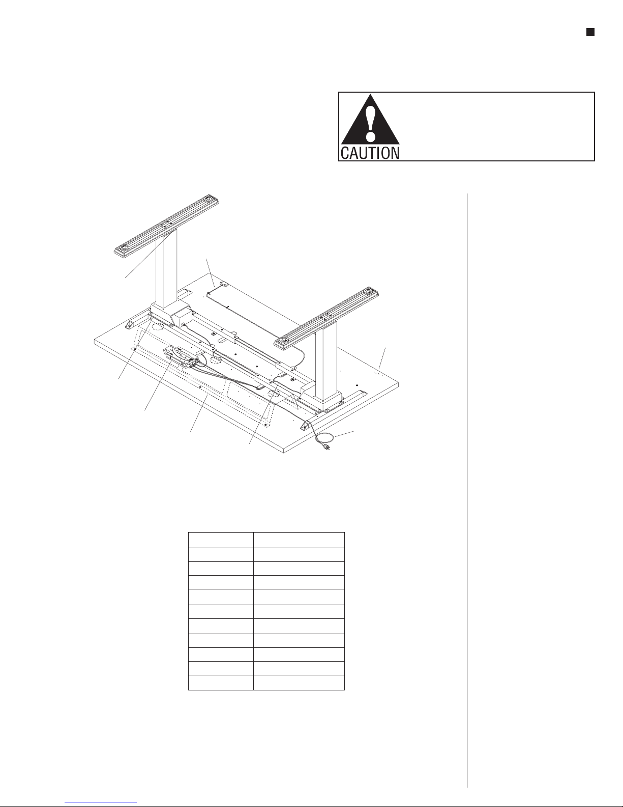
Figure 7 - Behind Cross-
able Depth
table top
leg control
cord (short)
cross-tube
assembly
control
box
Toggle® Tables - Dual Motor Height Adjustable Base, Model EL
key
pad cord
(optional)
wire
trough
Tube Assembly Wire Trough, 30” or 36”T
Model Number Operating Load Capacity
TOGL2448EL 220 lbs.
TOGL2460EL 210 lbs.
TOGL2472EL 200 lbs.
TOGL3048EL 210 lbs.
TOGL3060EL 200 lbs.
TOGL3072EL 185 lbs.
TOGL3648EL 200 lbs.
TOGL3660EL 185 lbs.
TOGL3672EL 170 lbs.
TOGLC3048EL 180 lbs.
Table Operating Capacity Chart
leg control
cord (long)
power
cord
Assembly Instructions
Assemble units as described herein only. To do otherwise
may result in instability. All screws, nuts and bolts must be
tightened securely and must be checked periodically after
assembly. Failure to assemble properly, or to secure parts
may result in assembly failure and personal injury.
Wire Trough (Optional)
Note: The wire trough is an
optional part that must be
ordered separately.
Note: Control cables can be
routed differently than shown.
The control box can be mounted
to the underside of table tops
24” in depth at one location
between the cross-tube
assembly (Figure 5). Control
boxes mounting under table
tops 30” or 36” in depth can
mount in one of five mounting
locations, one being the same
as the control box mounted
between the cross-tube
assembly on 24” table tops
(Figure 5). If the control box is
mounted between the cross-tube
assembly, reference figure 5 for
placement of the wire trough.
A 30” or 36” depth table top
is the only depth which will
allow a control box to be in
the following locations. If the
control box is mounted to the
front user side of the table,
reference figure 6. Mounting
to the front of the table does
not require the use of the
“optional key pad” (Figure 6).
If the control box is mounted
behind the cross-tube assembly,
reference figure 7.
5
Page 6
Toggle® Tables - Dual Motor Height Adjustable Base, Model EL
Assembly Instructions
Assemble units as described herein only. To do otherwise
may result in instability. All screws, nuts and bolts must be
tightened securely and must be checked periodically after
assembly. Failure to assemble properly, or to secure parts
may result in assembly failure and personal injury.
Electrical Rating:
Input: 120V/60HZ/5A Output: 216VA/24V
WARNING: Risk of Injury-Do not exceed recommended operating loads. See Table
Operating Capacity Chart on page 5.
Duty Cycle: 10% per hour. (2 minutes “ON” and 18 minutes “OFF” at continuous
operation under load.
This table is not designed for continuous operation. Table operation
must not exceed duty cycle.
IMPORTANT SAFETY INSTRUCTIONS
When using an electrical furnishing, basic precautions should always be
followed, including the following:
Read all instructions before using (this furnishing).
DANGER: To reduce the risk of electric shock:
1. Always unplug this furnishing from the outlet before cleaning.
WARNING: To reduce the risk of burns, fire, electric shock, or injury to
persons:
1. Unplug from outlet before putting on or taking parts off parts.
2. Close supervision is necessary when this furnishing is used by, or near
children, invalids, or disabled persons.
3. Use this furnishing only for its intended use as described in these
instructions. Do not use attachments not recommended by the manufacturer.
4. Do not use outdoors.
5. WARNING: Risk of Electric Shock-Connect this furnishing to a properly
grounded outlet only. See Grounding Instructions.
SAVE THESE INSTRUCTIONS
Toggle Troubleshooting Guide
** Table “Zero Setting”
Press and hold the Up button for two seconds then release. Next, press and hold the Down button until table has reached its lowest position then release Down button. Then, press
the Down button again and hold for approximately 10 seconds. The table now re-set at its “Zero Setting” position and is ready to operate. Note: Intellect System Protection (ISP)
detection is disabled during “Zero Setting” Operation.
Warning: In spite of Intellect System Protection (ISP) being in place, there may still be a risk of pinching in exceptional cases, as it is not only the control unit, but also the
interaction between the mechanical and electrical systems that is responsible for cutting out the motor. In addition, the mechanical components, motor and ambient conditions all
affect cut-out sensitivity. KI and the control unit manufacturer, cannot therefor eliminate this residual risk completely or accept any liability.
Symptom Reason Corrective Measure
Table does not move. • Incorrect or no voltage.
• Verify there is power to the table. Make sure the table is properly
plugged into a functioning power source. Make sure the power cord is
fully engaged into the socket on the control box.
• Table requires “Zero Setting”.
• One of more component connectors has come disconnected
or not fully connected.
• Perform Table “Zero Setting” **.
• Verify all connectors are securely connected to legs and to control
box. Disconnect and re-connect each one to ensure it is properly
seated, then preform a Table “Zero Setting” **.
Table Base moves erratically
or is tilted (one leg moves,
• Damaged components or connectors.
• Table has exceeded its duty cycle.
• Control box is not properly synchronized with the legs. • Ensure that all cables connections are fully seated. Then perform a
• Check for visible damage to all connectors and connector receptacles.
• Allow table to cool.
Table “Zero Setting” **.
one does not).
Table base stops and will
only move down (or up).
• Table may be at its highest (or lowest) position (range 26” at
the lowest to 52” at the highest) and then can only go down
• Press the other switch button.
(or up).
• Table or an object on the table is colliding with an obstruction.
• Table is overloaded or the weight on the table is not evenly
distributed.
• Control box is not properly synchronized with the legs.
• Perform a visual check and clear any obstructions.
• Reduce load and attempt to adjust the table.
• Ensure that all cable connections are fully seated. Then perform a
Table “Zero Setting” **.
All above corrective
measures have been applied
• Control Box is damaged. • Forward the part number (P/N) off the control box label (located next
to receptacles) to your Customer Service Representative.
and table still does not move.
Table does not reach its
• Table limits may need to be programmed. • Contact your customer service representative.
correct highest (52”) or
lowest (26”) position.
6
Page 7

Toggle® Tables - Dual Motor Height Adjustable Base, Model EL
Assembly Instructions
7
Page 8

Toggle® Tables - Dual Motor Height Adjustable Base, Model EL
Assembly Instructions
1330 Bellevue Street • P.O. Box 8100 • Green Bay, WI 54308-8100 • Tel 1-800-424-2432 • www.ki.com
© 2017 Krueger International, Inc. All Rights Reserved • Code KI-62527R7/KI/PDF/0417
 Loading...