

TOC AVIATION 35% Yak 54 User Manual
TOC AVIATION
35% Yak 54
W;’’’kllingspWingspaFlying Weight: 30lbs
Specification:
Wingspan :107”
Length: 95”
Flying weight:30 lbs
Wing area: 2223 sq. inches
Engine: 100 gas engine
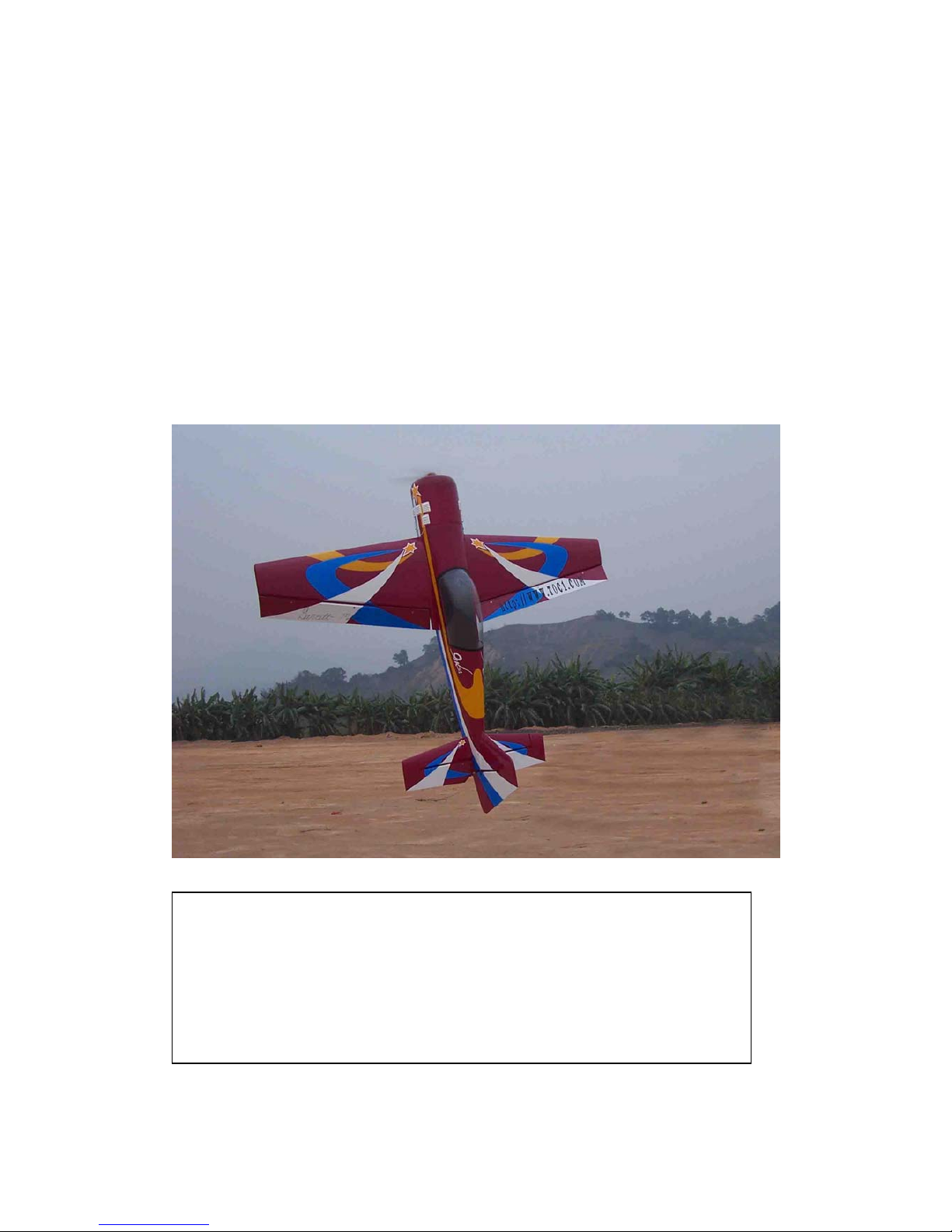
1. Servo installation:
Locate the servo bay holes and cut the
covering back. Take your covering iron
and tack the covering around the edges.
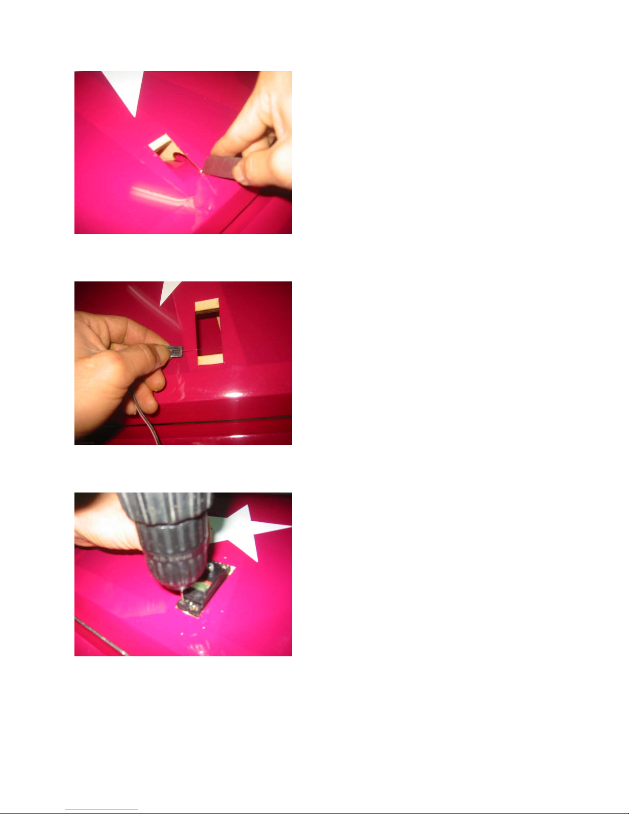
2. Servo installation:
Use the fishing line to feed your servo
lead through the wing ribs out to the roo
t
of the wing.
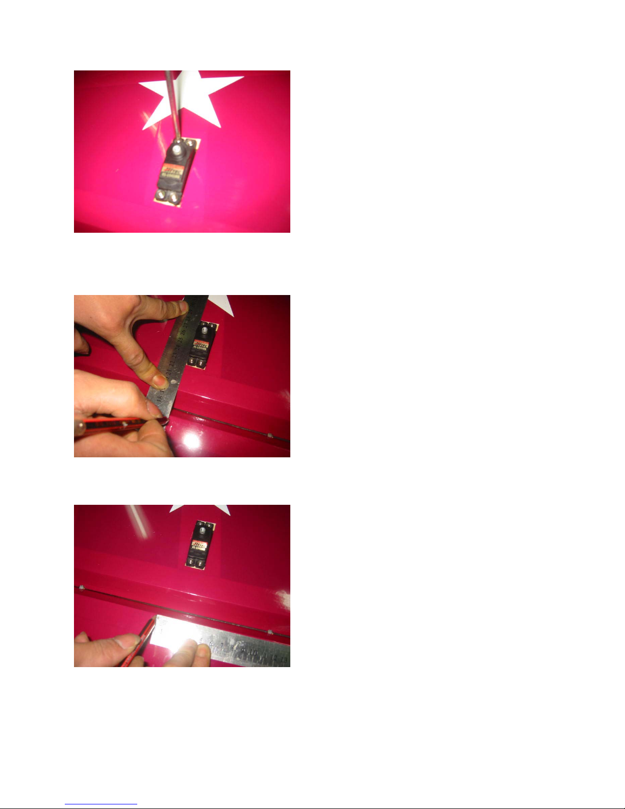
3.Servo Installation:
After placing the servo into the bay, drill the
servo mounts and then use the servo
mounting screws that are provided with
your servo.
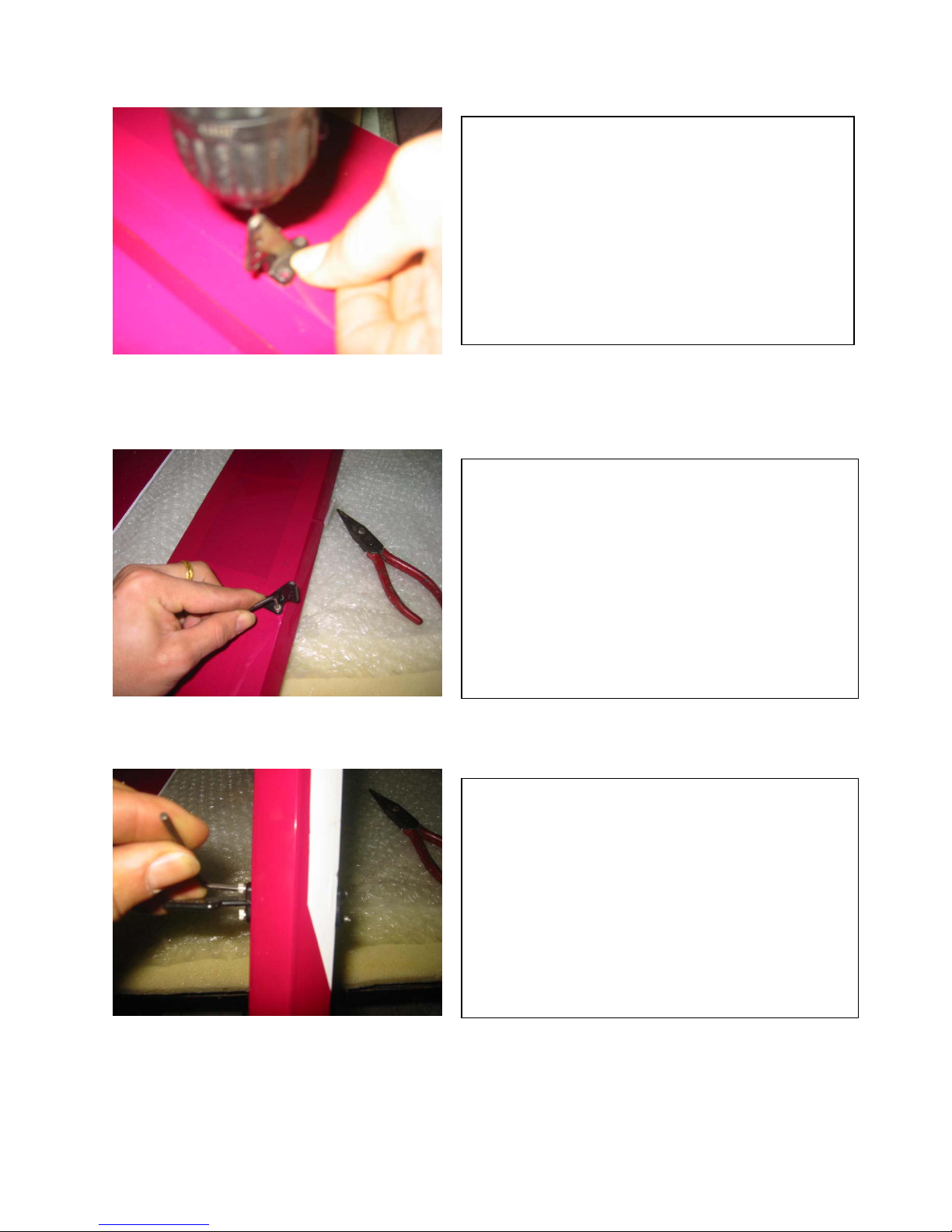
4. Once the servo is mounted, it shoul
d
look like the picture provided. Fo
r
finial assembly you may want to add
a
drip of thin CA to the screw holes an
d
re-drill. This will provide a secure
mount.
5. Once the servo is installed measure
the length of the push rod.
6. Make sure your control horn is place
d
5mm toward the root of the wing. This
measurment is taken from the edge o
f
the servo.
7. Center the aileron and position the control horn as close to
the leading edge as possible. Pre-drill the holes and use the
allen screws provided to mount the control horn. Make
sure to use a drip of thin CA in the hole to provide a stronge
r
mount.
8. Tighten the allen screws, once complete the control hor
n
should look like the picture provided.
9. Make sure that the allen bolt goes through the entire
aileron and into the mounting back plate.
10. Hinge installation
Mix the proper amount of epoxy and coat the hinge
hole.(This is a very important step so make sure you have
p
lenty of epoxy in the hole).
Fig.10
11. Wipe the excess glue away from the hinge and off of the
covering once the surfaces are taped together.
12.Installing pushrods:
Use some type of clamp to help center the
aileron.
13.Measure the length of the pushrod and mark.
Make sure you have plenty of threads left tha
t
will be able to screw into the ball link an
d
control horn (provided).
14. Once you have the proper length, cut the
p
ushrod and install.
15.Place the servo arm back onto the servo an
d
tighten the screw. Make sure the arm is at a
90-degree angle to servo with the control
surface at center.
16.Main Landing Gear Installation:
Use the four 1/4×20 bolts provided to mount the
gear to the gear plate. Back the bolts from the
inside with the four lock nuts. Once the locknuts
are tight you may move to the next step.
17.Tail Wheel Installation:
Install your preferred tail wheel to the hard woo
d
at the rear section of the fuselage. Here is an
example of our installation.
18. Install the blind-nuts needed for the tail wheel
through the acess hatch in the rear portion of the
fuse.
 Loading...