

Operating Instructions
TVT-S8S Tobin Video Transfer
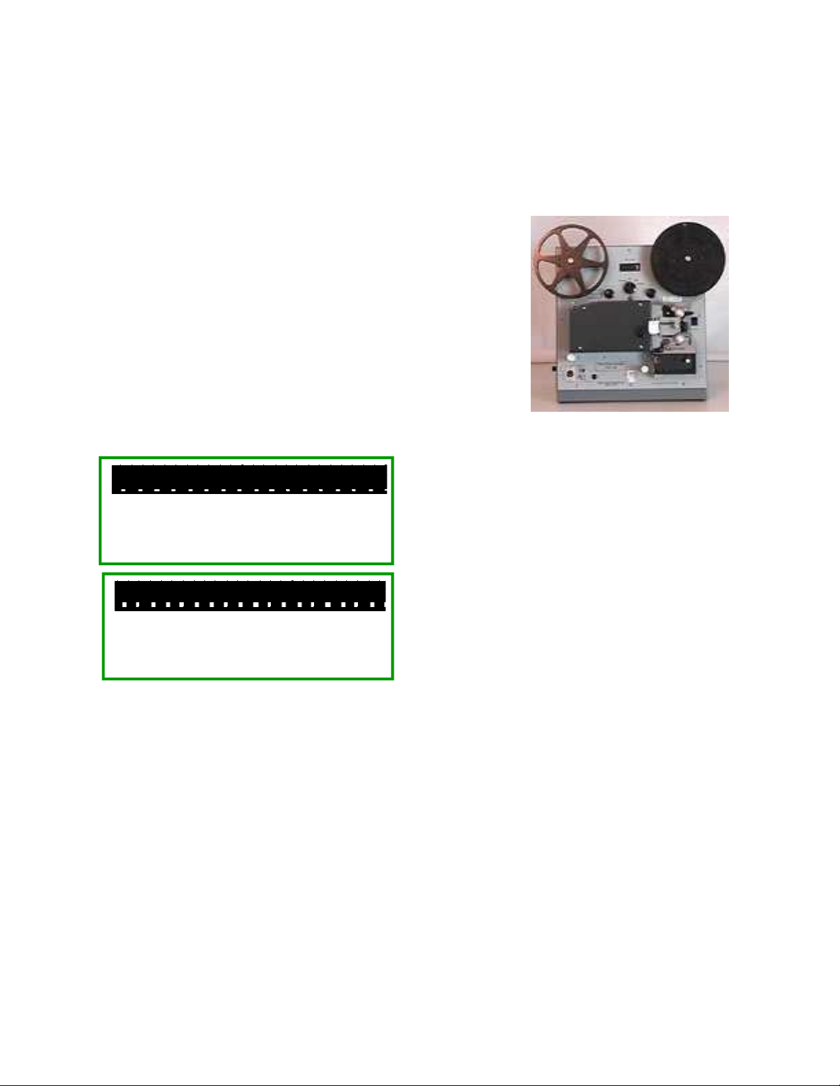
Super-8 Sound
Basic Operation
Turn on the power with the switch on the right rear of
the TVT-S8S. Check that the left-hand switch is in the “Peak
Auto” position, the knob to the right of it is in the upper “Auto”
position or pointing towards the right, and the right-hand rotary
switch is in the “Normal Speed” position.
(Note: see page 9 for identification of the items on the
front panel.)
Switch the unit to “Still” and note that there are no hairs
or lint visible in the picture on the underscanned video monitor.
If there are any, swing open the film gate and brush or blow out
the hairs. Switch back to “Stop” and close the film gate.
Super-8
Regular-8
reel hub with the spokes in the reel spindle. If the reel is correctly prepared, the perforations
(sprocket holes) in the film will be towards you, with the emulsion side (the side with the
picture) facing to the right, while the film is hanging down from the right-hand side of the reel.
There should be about 4 feet (1.25m) of leader before the first picture. If any of this is not the
case, return the film reel to the preparation department for correction.
If the leading edge of the film is mangled, trim it straight across in between perforations
and make extremely small bevels on the corners with scissors, if the film preparation
department hasn’t already done so. If it is bent or curled, flatten it.
Set the Speed knob to 0.5 or half speed. Switch to “Forward”. While constantly holding
down the “Push” lever with your left hand, feed the film into the upper channel with your right
hand.
NOTE: There are two clear plastic windows below the film gate area. You should be
able to see the white leader pass straight down past the left hand window. If it jams and starts to
bunch up, immediately stop and switch to Reverse to back the film out for repair or flattening.
NOTE: After the film is seen to go straight down past the left hand window, a couple of
Check that the film is in fact Super-8. If it
is magnetic sound film, the film itself (but not
necessarily the white leader) will have a brown
stripe on each edge, on the side facing to the left.
Super-8 film has small sprocket holes and
normally comes on a reel with a 1/2" (12.7mm)
diameter center hole. Regular-8 film has larger
sprocket holes and normally comes on a reel with a
5/16" (8mm) diameter center hole.
Threading:
Place the full reel of film on the right-hand
“Supply Reel” spindle, matching up the slots in the
1

seconds later you should see the film through the right hand window pass curving to the right.
After the film emerges from the bottom channel, release the “Push” lever. At this time
you can increase the speed to the normal running rate, and lead the film until about 3 feet (1m)
has emerged. (If you accidentally let go of the Push lever too soon, stop the machine and back
out the film, to begin over.)
NOTE: Avoid contact with the take-up reel and the Manual Advance knob as they will
be turning rapidly.
NOTE: After releasing the Push lever, you will see through the left-hand window that
the white leader has formed a free loop curving over to the right and back. This free loop is
necessary to isolate the intermittent film movement through the film gate, from the smooth
movement required when it is passing over the sound playback head. If the free loop is the
wrong size, the sound will not be in sync with the picture. See page 9.
Switch to “Still.” (You can carefully apply a braking force to the take-up reel to slow
down its spin, without sticking your fingers in the spokes.) Attach the film to the take-up reel,
turning the reel clockwise a couple of turns, after leading it around the two round plastic guides.
Turn the Manual Advance knob counter-clockwise a few turns to ensure that the film
advances intermittently through the film gate. Switch to “Forward” to preview the film. It
should be right way up (people’s heads and the sky at the top). The frameline (the dividing line
between pictures on the film) should not be visible; if it is, adjust the “Framer” knob or screw
while running, until it is not seen.
Switch to “Reverse” and run until the picture is all back on the supply reel and there is
about 1 foot (.3m) of leader film between the supply reel and the film gate, then switch to
“Stop.” Push the “Reset” button to zero the footage counter. Note that while running in reverse
you will likely get blurring or travel ghost, as the shuttering is optimized for running forward.
Start the video recorder. Switch the TVT-S8S to “Forward” and you will be recording
the film on video.
Loop Loss:
The film should be inspected, repaired and cleaned before it comes to you for transfer.
In case a bad splice or multiple damaged perforations causes loss of the lower film loop and an
increased upper loop, this will cause a chattering noise and the picture will start jumping up and
down, along with garbled sound. Turn the “Loop Restorer Knob” sharply to the right and let it
fall back, to reset the loops. If this doesn’t work, turn to “Stop” and also stop the video recorder.
Turn the Ratcheting Sprockets to reset the upper film loop to midway between the clear plastic
guide rails, and so that the lower film loop is curving to the right and back again as seen
through the left-hand window as set with the Loop Restorer Knob. Then resume the transfer.
For a high grade transfer, running the repaired film should resume from an earlier scene change
in the film, doing a video “assembly edit” using a video recorder with a flying erase head. Note
that it may take about a foot for the picture and sound to become steady, so back up the film to
a foot before the start of the desired scene.
At the end of the film, switch to “Stop” and stop the recorder. Record the film length
count for billing purposes, if your company charges by the foot or meter.
Attach the end of the film straight across to the supply reel, without going through the
sprockets and gate, and turn the reel a couple of turns counter-clockwise. Switch the Rewind
“On” and monitor closely because the film rewinding is very fast, and when the film is fully
2

rewound turn the Rewind switch “Off” immediately. Remove the supply reel after it stops, and
you are now ready to transfer the next reel.
Installation
Connect the TVT-S8S machine to a suitable video recorder. This is often a Mini-DV
(digital video) or else DVD (digital video/versatile disc) recorder, or less commonly these days
a VHS (video home system) machine. There are two video output jacks on the front of the
machine. Both can be used at the same time if desired:
•
The S-Video (“Separate”-video) Y/C output may give a cleaner video signal in many cases,
as the luminance (brightness or Y) and chrominance (color or C) signals are sent through
separate wires and will not interfere with each other, and thus not cause odd artifacts to
appear in the picture. This preferred connection is with the Mini-DIN 4-pin cable supplied.
•
The conventional video output is used in case the recorder lacks an S-Video input. The jack
is a professional BNC type, so use the supplied BNC to BNC locking cable to connect to
commercial video equipment. Use the BNC to RCA phono type cable or adapter supplied,
to connect to consumer equipment.
Audio Pitch Correction:
Because of technical video requirements, the TVT-S8S 1CCD telecine runs the film at
speeds that are a bit adapted from the original filming rate. For the happiest customers, the
audio should be routed through a Harmonizer or Pitch Shifter (not included) so the pitch of
voices and music is normalized. In use, the pitch is increased for 18 FPS films and reduced for
24 FPS films, as the former are run a bit slow and the latter are run a bit fast. The external
device is set so the Dry (uncorrected) output is zero and only the Wet (corrected) signal is used.
For NTSC machines, at Normal speed raise the pitch by 5.1% and at Pro speed lower
the pitch by 6.6%.
For PAL units, at Normal speed raise the pitch by 8% and at Pro speed lower the pitch
by 4%.
•
For most equipment, use the supplied RCA phono cable to connect the audio out of the TVT
-S8S to the pitch corrector. To record the mono audio on both channels of the usual stereo
recorder, plug the recorder end of the pitch corrector output into the jack of the supplied Ycord which has two audio plugs.
•
For broadcast equipment, use an XLR cable (not supplied) to send balanced high level audio
from the 3-pin XLR male jack on the TVT-S8S to a suitable input on the other equipment.
Plug the TVT-S8S into a source of 100 to 240 volts AC (alternating current) at 50 or 60
Hz (Hertz, or cycles per second.) For safety and to minimize electrical interference the third
wire should be grounded (earthed.) Turning on the unit will cause the footage counter to light
up, and for black video to be output.
Monitoring
A color video monitor should be used to help you best oversee the transfer operation.
We recommend that the picture monitor be connected to the output of the recorder, so the tape
or disc playback can be spot-checked for quality. We also suggest the use of an “Underscan
Monitor” which enables the entire video signal to be seen by the operator. Such a monitor can
3

be recognized by an Underscan-Normal switch. (In the
underscan position, the active video area is bordered
with black.)
This is because ordinary monitors and TV sets
have varying degrees of “overscan.” The picture is
larger than the picture tube, so the edges are cut off. The
amount of underscan is not well standardized, may not
be centered, may be out of adjustment, and may hide
defects that could be seen on a different TV set. For
Conventional TV
or Monitor Cuts
Off Picture
Underscanned
Monitor Shows
All The Video So
No Surprises
example, the film may be out of frame so that the
frameline is visible on some receivers but not others. Or, a piece of lint may be lodged on the
edge of the aperture and working its way into the frame. To guarantee that the frameline or
hairs will not be visible to anyone, no matter how their TV set may be adjusted, the transfer
process should be watched with an underscan monitor so the entire video signal can be seen.
There can be small artifacts on the extreme edges, such as dirt specks stuck to the aperture,
which will not be a problem as the customer will not see the entire video frame on his TV set.
When demonstrating the process or results to the public, the monitor should be switched
back to the Normal position to prevent misunderstandings or long explanations.
If an Underscan monitor is not available, you can manage with one having Pulse Cross
(Pulse Delay.) This puts the corners of the picture in the middle of the screen. It is possible to
use this function to check for framing and hairs although it is less convenient and can be
confusing.
It is also possible to use a device called a Line Doubler or Scaler, and a conventional
SVGA CRT computer monitor with size adjustments, to accomplish a similar underscanned
result instead of buying a more expensive underscanning video monitor. However, there will
not be a single button for switching between the underscan position and normal, and the left or
right edge of the picture may be missing some of the area that would be visible on a true
underscanned video monitor.
Other Needs
Film will be received from the public in various states of disrepair, with bad splices,
winding turned over on the reel, being mounted on the wrong type reel or the wrong way out,
no leaders, etc. and a facility must be provided for making the footage ready for transfer. This
requires at the minimum a pair of film rewinds, with adapters if needed for super-8 reels, a
supply of film leader and empty reels, a film splicer, and a way of cleaning excess dirt off the
film. Ideally there will be a light box for looking through the film, and a light above the editing
bench to reflect light off the film.
Refer to the first section of these instructions for a description of how the film should be
wound on the reel. There should be at least 4 feet of leader in good condition on the start for
proper threading of the TVT-S8S, and enough leader on the end to thread the film cleaning
device. Torn film sprocket holes and crooked splices should be removed to prevent transfer
problems.
Small rolls should be spliced together for fast and efficient transfer. A properly made
cement splice, using fresh cement, is preferred. The smoothest transit of splices occurs when
you have made a beveled splice using an (unfortunately discontinued) Agfa or Bolex splicer,
4

where the total thickness at the splice is about the same as unspliced film. (Fuji Single-8 and KMart Focal film was on polyester base and must be tape spliced.) When making tape splices,
ensure that the sprocket holes are not covered up and the tape is on straight, on both sides of the
film.
NOTE: The multiple bends in the film path of the TVT-S8S puts greater demands on the
integrity of cement splices. If they are weak owing to using old cement, or not being fully
scraped, these are more likely to pop apart than in most silent equipment with a simpler path.
We suggest using 400 foot (122 meter) reels, and cans or 7" size white 1/4" audio tape
boxes. Usually if 8 small 50' rolls of super-8 film is wound on each reel, this will enable two of
the reels to fit on each 1 hour tape or disc with minimum waste and no need for time-consuming
tape editing or overlaps. Mark the leader on the head (beginning) of the reel with the customer’s
name or job number, and the reel number, to avoid mixups. Leader with a matte finish can be
written on with pencil, while shiny leader can be marked with a Sharpie or India ink. Ensure
that that the cleaning step does not remove the reel identification. Storage cans should be
ventilated for slight air circulation, to prevent film deterioration from “vinegar syndrome.”
Advise the customer to keep his film in a cool, dry, dark place to prevent fungus growth. You
want the film to be in good condition so you can transfer it again when the next super
generation of video equipment formats makes the present transfer obsolete. :-)
NOTE: Super-8 mechanisms are fussy about splices, compared to regular-8 ones. If
your cement splices of super-8 cause lost loops, change the direction of splicing by winding the
film right to left on the bench while splicing, instead of left to right, so you are scraping the
outgoing film instead of the incoming one. Having the splice accordingly lap the other way (so
the sharp leading edge of the thick splice rubs against the mechanism’s pressure plate instead of
hitting the bottom of the minimally undercut aperture plate opening) will give more reliable
running.
After each reel is spliced and repaired, it is rewound through the film cleaner device on
to the proper reel, which restores the reel to being heads (beginning) out instead of tails (foot or
end) out, and sent to the transfer room. Note: When using a liquid cleaner, view the rewinding
film by reflected light to make sure it is dry again before it is wound up, or else the film may
dry with “shoreline” marks on it. You can wind quite fast if not using an excessive amount of
solvent.
IMPORTANT NOTE: Film that is not lubricated will cause noisy unsteady running
and can lead to film damage. Even some newly processed films are returned unlubricated,
owing to laxity or environmental concerns by the processing lab. The cleaning fluid should
have a small amount of wax dissolved in it to provide lubrication for smooth transport through
the TVT-S8S or through the customer’s projector. A suggested amount is a lump of candle wax
or beeswax the size of a pea ground up and dissolved in a pint (half liter) of solvent. Cleaning
solvents that are widely used include methyl chloroform (toxic fumes), perchloroethylene (dry
cleaning fluid) (toxic fumes), Freon TF (ozone depleting), or 99% isopropanol (isopropyl
alcohol) (flammable). There are also commercially mixed film cleaners with lubricant. Cleaning
must take place in a ventilated area. Some users report that using Pledge Beeswax furniture
polish sprayed on a rag, with the film wound through it while still damp, does an excellent job
of lubrication.
Exposure Correction
The correction uses your choice of Peak or Center-Weighted Averaging sensing, for
5

optimum results from a variety of original moderate over- and under-exposure conditions. This
is selected with the Peak - Manual - Average switch to the left of the rotary Auto - Manual
knob. Peak sensing is recommended for reasonably well-composed film, maintaining the mood
of the film. Average sensing is used for film that is strongly backlit (shooting into the sun) or
that is dark and also has a light source (movie light or bright window) near the edge of the
screen, or that is very badly overexposed. A minimum brightness level can be set with the
Manual knob, to prevent over-reacting to flashbulbs going off and the like.
For critical transfer for fussy customers who are willing to pay extra, the brightness can
also be set fully manually. This latter option usually means that the video must be edited later,
to remove the overlap when starting and stopping the TVT-S8S for each brightness correction.
Theory of Operation
The conventional means of film to video transfer uses a projector with a specific
number of shutter blades, attached to the mechanism and rotating with it. One blade is used to
obscure the film while it is being quickly pulled down to the next frame; additional equal blades
are used to get the desired interruption rate, which must be a whole multiple of the video field
rate. The blade complement might be either 2, 3, 4 or 5, depending on speed and video
standard. That is, for 24 FPS (frame per second) transfers to NTSC (USA type) video the
projector will have 5 blades. For running at 20 FPS you would need 3 blades. This type
machine will usually give more or less flickerless results at only one speed. Some old
equipment requires that the operator frequently tune the speed to minimize flicker and
complaints. Usually the running speed is quite inaccurate compared to the original amateur
filming rate, leading to complaints. Flutter from the stretchable drive belt and claw return spring
gives some residual flicker even if the speed is nominally correct. Take-up and rewind spindles
are friction coupled and will eventually wear out. Lamps are expensive and can be hard to find,
and frequently burn out. The unit has no, or a poorly performing, exposure correction ability,
leading to complaints.
In the TVT-S8S 1CCD however there is specially timed electronic shuttering in place of
a physical shutter. This permits precise multiple speeds to be obtained without any flicker.
The NTSC (USA video) models run at 8.571, 17.126 and 25.689 FPS (frames per
second.) The PAL (European video) models run at 8-1/3, 16-2/3 and 25 FPS.
Sound movies were mostly filmed at 18 FPS however. Sound film audio should be
looped through an external harmonizer or pitch shifter (not included) to correct pitch, so that
voices of family members are heard with normal pitch, although the pacing will still be a bit off.
Individual direct drive torque motors are used for take-up and reverse/rewind reel
functions, eliminating slipping clutches.
The light source is a wide-spectrum white LED (light emitting diode) that should last for
years. The output is of all wavelengths of visible light, and there is little or no IR (infrared) or
UV (ultraviolet) radiation present to heat, fade or burn the film. Its brightness is controlled to
automatically even out badly exposed film. (There is however no hope for the very worst film
you will see!)
Speed Change:
The Speed is changed with the rotary switch on the panel. The Normal speed is used for
6

18 FPS home movies, sound or silent. The Pro speed refers to 24 FPS film that was shot by
cameramen with commercial applications in mind.
Note that you will need to also change the setting of the external harmonizer or pitch
shifter, to suit the different running speed. See the Installation section above.
Other Information
The TVT-S8S has a “Mechanism Hours” timer to measure how long the main drive
motor and the mechanism have been running. This only advances in the Forward and Reverse
modes. The count is remembered without need for batteries when the unit is turned off. A time
interval for servicing the drive motor, magnetic head and mechanism has not yet been
established.
Cleaning the sound parts:
If the audio has a muffled quality, there may be a dirt buildup on the magnetic head. To
reach it, remove the sound cover. To clean, push down and hold the “Push” autoloading lever to
raise the black plastic pressure pad from the head, then clean the head with a cotton swab that
has been moistened with a mild solvent such as isopropyl alcohol.
A dirt or oil buildup on the rubber roller can cause “wows” in the sound. To clean it,
give it a spin and lightly apply the cotton swab and solvent while it is turning by flywheel
action.
If cleaning the head does not cure muffled audio from a sound film that is known to be
good, the head may need adjusting or replacement.
Service adjustments:
• After long use, the white balance of the LED and camera module could change. To reset the
white balance, turn to “Still” and “Peak Auto” without film but with a 0.7ND neutral filter in
the light path that includes a small amount of cyan and blue filtering. Observe the C output on
an oscilloscope or waveform monitor and adjust the two left-hand pots on the back of the
Camera module for minimum color subcarrier. Be very careful when adjusting these tiny and
delicate pots so they are not damaged or torn loose.
• Automatic exposure setting should be quite stable. Current optimum factory setting is .90
volts p-p with no film in the gate. Average film will then reach about 100 IRE while “all white”
overexposed film will peak around 85 IRE. The “Average” setting is for .70 volts with no film.
Voltage readings are peak to peak, and will be double if measuring an unterminated output.
• Focus, centering and magnification are factory set and locked in place, and should not be
disturbed. A focus jig is available from TCS for re-setting these. Do not disturb the sound head
adjustments.
• In case of odd symptoms, first check the output voltage of the switching power supply
modules. These should be +12, —12 and +24 volts DC, ±5%. The voltage should change little
no matter what settings are made to the operating controls. The 24 volt supply may sag
momentarily while the drive motor starts running.
• If dust accumulates on the optics it should be removed with a clean camel’s hair brush or air
blower. Fingerprints must be removed immediately with lens cleaner and lens tissue, following
the instructions included with them. There should be no need to open the light source module.
• After long use, if the fixed plastic film guides show excess wear, they can be loosened, rotated
7

1/5 or 1/4 turn and re-tightened to get a fresh wearing surface. This can be done three or four
times.
Suggested Sources of Supplies
Super-8 400' reels in boxes of 200 pieces:
Tayloreel Corp. www.tayloreel.com 770-503-1612
Super-8 400' reels (8mm SMD component reels 7") in boxes of 100 pieces, Item VP-A708-08: Media Distributors,
formerly Plastic Reel Corp (PRC) 800-929-1637 or (818) 980-9916 Attn: Mario in West, 800-772-4748 in East
White boxes for 7" diameter 1/4" audio tape reels in boxes of 180 pieces:
Protape Northwest 800-331-6107 and probably other suppliers
Super-8 Kodak White Movie Leader in 50’ roll: # 191 0116
Super-8 Kodak White Movie Leader in dispenser box of 1000' (more economical): # 882 7362
Kodak Professional Film Cement 16 oz: #195 6176, 1 gallon: #195 6150, both plus $20 hazardous shipping fee.
Kodak ordering toll-free number: 1-800-621-3456 (1-800-621-FILM)
The former Kodak Presstapes are now sold by Urbanski Film, (708) 460-9082 http://www.presstapes.com
Some kinds of leader cannot be cement spliced. Ask before buying.
Christy’s (equipment, leader, reels in small quantity) 800-468-6391
Neumade (manufacturer of rewinds, leader) 203-270-1100
MPE (equipment, leader, reels in small quantity) 212-245-0969
Starex (leader) 201-997-1555
FCA (leader) 818-845-7651
ECCO makes a film cleaning device that is mounted between a pair of rewinds. These are sold by several dealers.
Film cleaning fluid is made by several companies or else you can use Freon TF, 99% isopropyl alcohol, etc. with a
small amount of wax dissolved in it for lubrication.
8

Function
Switch
Push and Hold for
Auto Threading
Counter
Reset
Optics
Cover
Attaching
Screws
Film Gate
Emitter
Socket
Manual
Advance
Knob
(Hidden)
Model, Serial,
Special Feature
Badges
Take-Up
Reel
Exposure
Controls
Film
Counter
Supply
Reel
Insert Film
Here
Rewind
Switch
Hours
Counter
(Hidden)
Speed Knob
Upper
Sprocket
Light
Emitter
Lower
Sprocket
Threading
Check
Windows
Loop
Restorer
Balanced
Audio
Normal
Audio
Composite
Video
— Signal Outputs —
http://www.TobinCinemaSystems.com
Guide Posts Y/C S-
Video
Framer
Screw
Cover
Screw
Emitter Advisory Tag
(Remove After Installation)
On rear cover (not shown): Power (mains) Inlet Jack, Power Switch
Tobin Cinema Systems, Inc.
TVT-S8S 1CCD Instr Rev 6-17-08
9
Sound
 Loading...