


Operating Instructions for models with Videology camera:
TVT-D8C, TVT-S8C Tobin Video Transfer
Dual-8 or Super-8 “My Own Telecine”
Basic Operation
Connection. The telecine does not have a power switch. The 3-wire plug goes into line
(mains) voltage of 100 to 240 volts AC, 50 or 60 Hz. The third grounding pin is for electrical
safety, and to minimize any electrical interference that could be generated or received by the
TVT. The video output is through a 4-pin MiniDIN Y/C S-video socket on the rear of the
camera housing. This connects to the DVD, Mini-DV or S-VHS recorder or computer of your
choice. Note that unlike competing units no computer is required. The recorder output should
connect to an underscanned video monitor. See below for an explanation.
Before Threading. Note: The operating controls are shown on Page 8. Check that there
are no hairs or lint visible in the picture on the underscanned video monitor. If there are any,
swing open the film gate and brush or blow out the hairs.
Film Format. Check that the film format is correct for the present TVT machine setup:
Super-8
Regular-8
below. Besides the basic Claw setting there are optical adjustments needed.
Video Standard. There are no “NTSC” or “PAL” designations on the TVT, the video
type can be inferred from the type of power (mains) plug. NTSC is used in North America, PAL
is used in Europe. Units shipped to North America with a USA power cord will be NTSC, and
units shipped to Europe with the European power cord will be for PAL, unless otherwise
specified when ordering.
Threading. Place the full reel of film on the right-hand “Supply Reel” spindle,
matching up a slot in the reel hub with a key in the reel spindle. If the reel is correctly prepared,
the perforations (sprocket holes) in the film will be towards you, with the emulsion side (the
side with the picture) facing to the right, while the film is hanging down from the right-hand
side of the reel. There should be about 4 feet (1.25m) of leader before the first picture. If any of
this is not the case, return the film reel to the preparation department for correction.
Threading the TVT-D8C. The TVT-D8C requires film reels that are not unbalanced,
and that are not bent and pinching the film edges.
The TVT-D8C has easy partly manual threading. This sprocketless design prevents the
•
The TVT-S8C is only for Super-8 silent
film. It will not accept Regular 8.
• Your TVT-D8C is set for Super-8 film
when the Claw lever is in the Super-8 (upper)
position and the 1/2" (12.7mm) supply reel spindle
adapter is installed.
• Your TVT-D8C is set for Regular 8mm
film when the Claw lever is in the Regular-8
(lower) position and the 5/16" (8mm) supply reel
spindle is uncovered.
The film will not advance through the gate
if the Claw setting is wrong. If the setup is wrong,
change to the other TVT-D8C setup as explained
1
film damage that could otherwise occur if a bad
splice sticks in the film gate and film sprockets
continue to drag the film through. Threading is
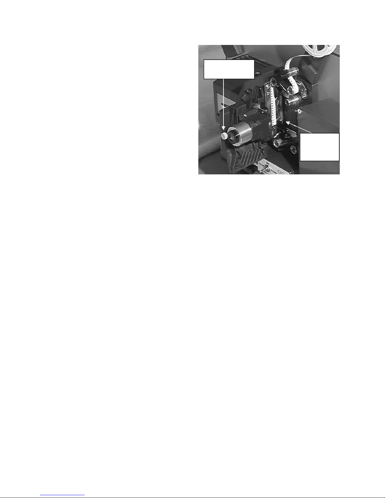
Magnification
Adjust Knob
done as follows.
Lift up the Rewind lever to minimize
drag on the running film. Swing open the lens
holder to reveal the film gate. Pull about 10
inches (1/4 meter) of leader past the film gate
area and insert it into the film gate. Route the
film around the three upper sprung rollers as
shown. Place the beginning of the leader just
below the second sprung edge guide, and make
sure it is in the proper channel. Close the film
Second
Sprung
Guide
gate. (Note: a rubber feed roller, if present, is not
used and can be disregarded.)
Threading the TVT-S8C. Push and hold down the clear plastic Autoload film guide,
run Forward, and insert the beginning of the film leader into the slot. Keep holding the guide
until the film emerges from the bottom sprocket. At this time you can release the guide.
Finishing the threading on both: Run the TVT in Forward, and it will automatically
go the rest of the way towards the take-up reel. Attach the beginning of the leader to the take-up
reel, turning the reel clockwise a couple of turns. It may attach automatically if using the correct
type of original reel, if one is available.
Preview the film. It should be right way up (people’s heads and the sky at the top). The
frameline (the dividing line between pictures on the film) should not be visible; if it is, adjust
the Framer knob until it is not seen. The film must be running to make the adjustment on the
TVT-S8C. The film can be stationary to make the adjustment on the TVT-D8C, but make sure
the film has not stopped in the middle of a pull-down cycle to the next frame. After previewing,
back up the film to before the first picture.
Recording. Start the video recorder. Switch the TVT to “Forward” and you will be
recording the film on video. Exposure errors in the film can be compensated with the Exposure
knob on the front of the TVT. See the note below about the Bias Light knob.
The film should be inspected, repaired, cleaned and lubricated before it comes to you for
transfer. A bad splice or multiple damaged perforations can cause the film to stick in the film
gate. On the TVT-D8C it may free itself momentarily, or you may have to help the film through
by pulling on it at the take-up reel. On the TVT-S8C it may lose the loops and give a blurred
picture. Pushing down briefly on the Autoload film guide may reset the loops. In a severe case,
you might have to stop for a second and rotate the knobs on the end of the sprockets to adjust
the loops so they are not hitting the plastic guides. You will hear a ratcheting noise when
turning the stiff sprocket knobs, this is normal and not harmful.
At the end of the film, switch to “Stop” and stop the recorder. Raise the take-up reel
arm. Attach the end of the film straight across to the supply reel, without going through the
rollers and gate, and turn the reel a couple of turns counter-clockwise. Switch to Reverse and on
the TVT-D8C engage the Rewind lever. When the film is fully rewound turn the switch “Off”
immediately. Do not stick your finger into the reel spokes or grab the edge of a plastic reel
while it is spinning, as this may cause injury. Remove the supply reel after it stops, lower the
take-up reel arm to normal, and you are now ready to transfer the next reel.
2
TVT-D8C Film Format Changeover
Claw Change: Move the Claw lever all the way up to Super-8 to center it for super-8 film.
Move the claw lever all the way down to Regular-8 to center it for regular-8 film.
Feed Reel Spindle Change: the Super-8 reel spindle adapter slides on and off. S8 film uses the
1/2" (12.7mm) spindle and R8 film reels have the 5/16" (8mm) size hole. (The “wrong” spindle
can be installed to suit film that is wound on the wrong type non-standard reel.) If available, an
original black plastic spindle adapter will be provided. If not available, an alternative adapter
will be furnished and this may require a rubber reel retainer to prevent the reel from falling off.
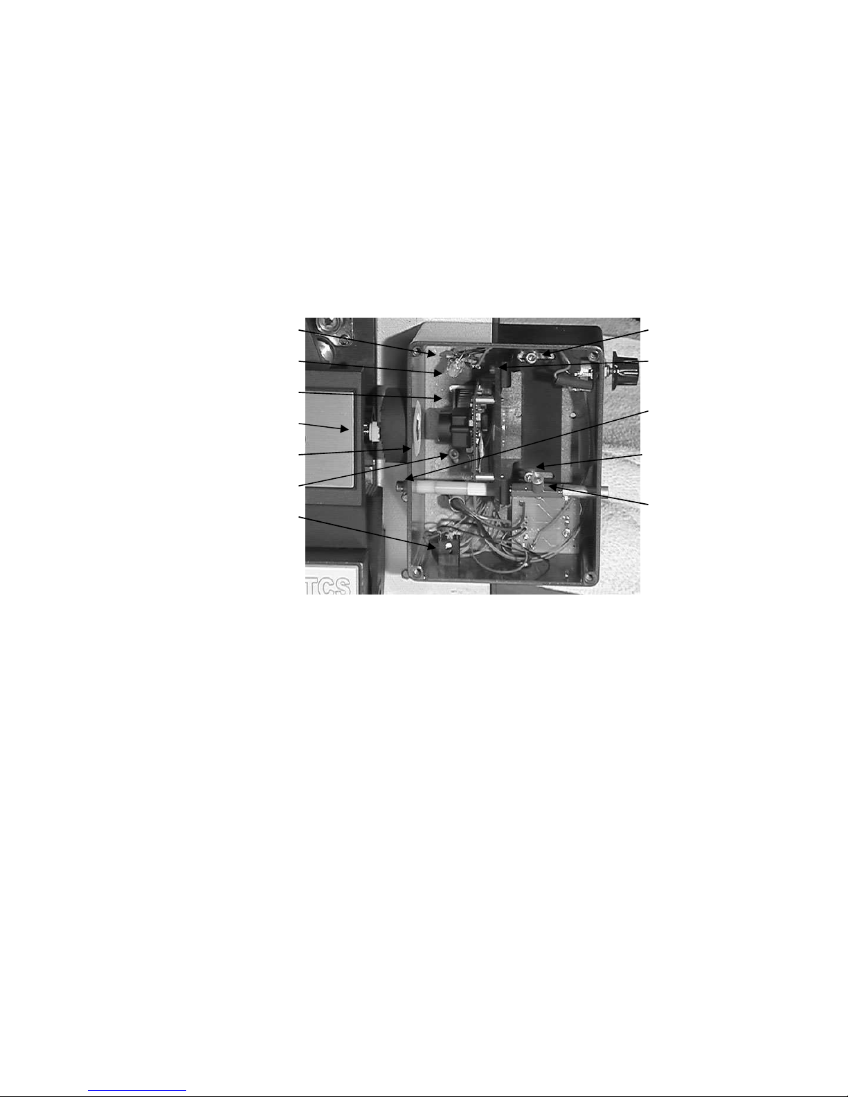
Coarse Framing Lock
Bias Light
Camera
Magnification Adjust Knob
Bias Light Reflector
Coarse Framing Lock
Camera Programming Port
Focus Lock
Centering
Lock
Left Focus
Slide Lock
Focus Lock
Right Focus
Slide Lock
Handle
Magnification Change: The effects of this and the following adjustments should be judged on
your underscanned monitor. The lens can be removed by fully unscrewing the Magnification
adjusting knob. An internal spring presses the lens against the adjustment. For Super-8 film, the
end of the lens with the retaining ring should face the film. For regular-8 film, the end of the
lens with the retaining ring should face the camera. For Super-8, adjust the Magnification screw
so the right end of the lens is protruding from the lens holder by about .2 inches or about 5mm.
For regular 8, reverse the lens end for end so the retaining ring is on the left, and slide the lens
so the right end extends only about .12 inches or about 3mm past the right side of the lens
holder. (When adjusting the TVT-D8C to match the aperture of a particular film camera, this
setting can be modified. Moving the lens to the left will further magnify the film (zoom in);
moving it right will reduce the size (zoom out). If you “zoom in” too much you will cut off
people’s heads and feet more often. If you “zoom out” too much you will have to change the
Framing Adjustment more frequently while working, and you are more likely to see and deal
with hairs and dirt around the edges of the camera’s filming aperture.)
Note: the following steps use the 7/64" Allen hex driver, with camera cover removed, and you
can best see what is happening if the room lights are very dim.
Centering Change: Run the film to be copied to a few feet past the end of the head leader. Pick
a spot with lots of fine detail or that is grainy, for easier focusing (below). If the film frame is in
3

the middle of a pulldown cycle, remove the lamp cover and turn the timing pulley counterclockwise so the film advances once and then is stationary. Loosen the Right hand part of the
Focus Slide a turn or two. Loosen the Left part of the Focus Slide by about a turn. Loosen the
Centering Lock Screw on the front of the camera plate by 1/8 of a turn, and slide the camera
plate in or out on the elongated holes to center the image. (Do not disturb the 3 small screws
that mount the camera module to the metal plate.) Tighten the Centering Lock Screw. Tighten
the left part of the Focus Slide. Tighten the right part of the Focus Slide.
Framing Adjustment: The Framer knob adjusts the framing of the image. If there is not
enough range, you can loosen the two Framing Coarse screws inside the camera case and move
the camera box up or down.
.
Focus Adjustment. Loosen the two Focus Lock screws slightly. Manually slide the camera
plate left and right to find the best focus. Re-tighten the two Focus Lock screws.
Monitoring Notes
A color video monitor should be used to help
you best oversee the transfer operation. We recommend
that the picture monitor be connected to the output of
the recorder, so the tape or disc playback can be spotchecked for quality. We also suggest the use of an
“Underscan Monitor” which enables the entire video
signal to be seen by the operator. Such a monitor can be
Conventional TV
or Monitor Cuts
Off Picture
Underscanned
Monitor Shows
All The Video So
No Surprises
recognized by an Underscan-Normal switch. (In the
underscan position, the active video area is bordered with black.)
This is because ordinary monitors and TV sets have varying degrees of “overscan.” The
picture is larger than the picture tube, so the edges are cut off. The amount of underscan is not
well standardized, may not be centered, may be out of adjustment, and may hide defects that
could be seen on a different TV set. For example, the film may be out of frame so that the
frameline is visible on some receivers but not others. Or, a piece of lint may be lodged on the
edge of the aperture and working its way into the frame. To guarantee that the frameline or
hairs will not be visible to anyone, no matter how their TV set may be adjusted, the transfer
process should be watched with an underscan monitor so the entire video signal can be seen.
There can be small artifacts on the extreme edges, such as dirt specks stuck to the aperture,
which will not be a problem as the customer will not see the entire video frame on his TV set.
The Underscan monitor is necessary when correctly adjusting the magnification,
centering, framing and focus when changing over between the S8 and the R8 settings.
When demonstrating the process or results to the public, the monitor should be switched
back to the Normal position to prevent misunderstandings or long explanations.
If an Underscan monitor is not available, you can manage with one having Pulse Cross
(Pulse Delay.) This puts the corners of the picture in the middle of the screen. It is possible to
use this function to check for framing and gate hairs although it is less convenient.
4

Other Needs
Film will be received from the public in various states of disrepair, with bad splices,
winding turned over on the reel, being mounted on the wrong type reel or the wrong way out,
no leaders, etc. and a facility must be provided for making the footage ready for transfer. This
requires at the minimum a pair of film rewinds, with adapters for regular-8 and super-8 reels, a
supply of film leader and empty reels, a film splicer, and a way of cleaning excess dirt off the
film. Ideally there will be a light box for looking through the film, and a light above the editing
bench to reflect light off the film.
Refer to the first section of these instructions for a description of how the film should be
wound on the reel. There should be 4 feet of leader on the start for proper threading of the TVT,
and enough leader on the end to thread the film cleaning device. Torn film sprocket holes and
crooked splices should be removed to prevent transfer problems.
Small rolls should be spliced together for efficient transfer, also the TVT-D8C
sometimes does not like small 50' reels. A properly made cement splice, using fresh cement, is
preferred. The smoothest transit of splices occurs when you have made a beveled splice using
an (unfortunately discontinued) Agfa or Bolex splicer, where the total thickness at the splice is
about the same as unspliced film. (Fuji Single-8 and K-Mart Focal film was on polyester base
and must be tape spliced.) When making tape splices, ensure that the sprocket holes are not
covered up and the tape is on straight, on both sides of the film.
We suggest using 400 foot (122 meter) reels, and cans or 7" size white 1/4" audio tape
boxes. Usually if 7 small 50' rolls of regular-8 film, or 8 small 50' rolls of super-8 film, is
wound on each reel, this will enable two of the reels to fit on each 1 hour tape or disc with
minimum waste and no need for time-consuming tape editing or overlaps. Mark the leader on
the head (beginning) of the reel with the customer’s name or job number, and the reel number,
to avoid mixups. Leader with a matte finish can be written on with pencil, while shiny leader
can be marked with a Sharpie or India ink. Ensure that that the cleaning step does not remove
the reel identification. Storage cans should be ventilated for slight air circulation, to prevent
film deterioration from “vinegar syndrome.” Advise the customer to keep his film in a cool,
dry, dark place to prevent fungus growth. You want the film to be in good condition so you can
transfer it again when the next super generation of video equipment formats makes the present
transfer obsolete. :-)
NOTE: The TVT-D8 has the super-8 claw position, above the gate, when running both
S8 and R8 films. Such mechanisms are fussy about splices, compared to regular-8 only ones
with the claw below the gate. If your cement splices cause excessive jamming in the film gate,
change the direction of splicing by winding the film right to left on the bench while splicing,
instead of left to right, so you are scraping the outgoing film instead of the incoming one.
Having the splice accordingly lap the other way (so the sharp leading edge of the thick splice
rubs against the mechanism’s pressure plate instead of hitting the bottom of the minimally
undercut aperture plate opening) will give more reliable running.
After each reel is spliced and repaired, it is rewound through the film cleaner device on
to the proper reel, which restores the reel to being heads (start) out instead of tails (foot or end)
out, and sent to the transfer room. Note: When using a liquid cleaner, view the rewinding film
by reflected light to make sure it is dry again before it winds up, or else the film may dry with
“shoreline” marks on it. You can wind quite fast if not using an excessive amount of fluid.
5

Important note on lubrication: Some film types are not lubricated in processing and
will give an unsteady image and noisy running until lubricated. This includes the current
Ektachrome 64T film as well as some private brand films made by other manufacturers. The
cleaning fluid should have a small amount of wax dissolved in it to provide lubrication for
smooth transport through the TVT-D8 or through the customer’s projector. A suggested amount
is a lump of candle wax or beeswax the size of a pea ground up and dissolved in a pint (half
litre) of solvent. Cleaning solvents that are widely used include methyl chloroform (toxic
fumes), perchloroethylene (dry cleaning fluid) (toxic fumes), Freon TF (ozone depleting), or
99% isopropanol (isopropyl alcohol) (flammable). There are also commercially mixed film
cleaners with lubricant. Cleaning must take place in a ventilated area.
Some users have adopted a modified means of lubrication. They spray Pledge Beeswax
furniture polish on to a rag, and wind the film through it while still damp.
Bias Light Adjustment
The TVT models with the Videology camera have a bias light to increase the amount of
detail that is visible in shadow areas of the film.
Block the normal exposure light with a piece of black construction paper or equivalent
in the image path, so the video monitor shows just black. Turn the Bias Light control fully
counterclockwise. Advance the Bias Light slowly clockwise until there is a just noticeable
lightening of the black on the monitor.
This is the approximate normal setting for transfers. It can be reduced at will to increase
the contrast of overexposed film, or increased to make a hazy, flat dream sequence for example.
Running Speeds
The TVT-D8C and TVT-S8C models run at one speed. This is 19.98 FPS (frames per
second) for NTSC video models, and 16-2/3 FPS for PAL video models. This design feature
gives smooth screen motion and the greatest degree of exposure correction for dark film. The
TVT gives frame by frame scanning in real time, with each film frame going to three video
fields. This gives smoother screen motion than duplicating entire video frames via computer.
Other Information
Routine service:
• After long use, the Claw Pivot and cams may need greasing. Instructions for this will be furnished on request.
Service adjustments and information:
• After long use, the white balance of the LED and camera module could change. To reset the white balance,
with no film in the gate, set the Exposure knob so the video level is 10-20% below the clipping point. Push the
“White Balance” pushbutton on the back of the camera. It will cycle between several color setting
combinations and finally settle down with a neutral white balance. Note that some cameras require that a
slightly colored filter be placed in the light path when setting the white balance, to get a neutral white when
actually doing a transfer. If so your camera requires this filter: _______________________.
• In case of replacing the timing belt, it will be necessary to reset the “Shutter Phase.” When the claw is in about
the start of a pulldown cycle, the top edge of the interrupter disc slot should be about at the center of the optointerrupter. The disc position can be changed when the TVT is stopped, by loosening the screw on the end of
the motor shaft. If there is residual travel ghost, move the disc relative to the shaft as follows: For a ghost
extending above a light object, turn the disc counter-clockwise a little. For a ghost extending below a bright
6

object, turn the disc clockwise a little. Then re-tighten the screw and re-check.
• Camera setup settings such as shutter speed, gain, white balance type and mirror function are all done at the
Tobin Cinema factory with a special jig and software program, and cannot be altered by the user. Do not
attempt to connect anything to the camera programming port on the bottom of the camera housing as no good
can come from this.
• In case of odd symptoms, first check the output voltage of the switching power supply. The voltage should be
15.6 volts DC.
• The TVT may malfunction if the Ground pin on the power cord is not connected.
• If dust accumulates on the optics it should be removed with a clean camel’s hair brush or air blower.
Fingerprints must be removed immediately with lens cleaner and lens tissue, following the instructions
included with them.
Suggested Sources of Supplies
http://www.urbanskifilm.com/
7

Take-up
Reel
Spindle
Lamp
Cover—Pull
straight out
to remove
Framer
Knob
Rewind
Lever
Behind
Reel
Supply Reel
Spindle
Film Gate—
Pull here to
swing open
Power cord and serial number nameplate are on the rear.
Tobin Cinema Systems, Inc.
http://www.tobincinemasystems.com
Exposure
Control
Claw Shift
Lever
8
Forward Still
Reverse
Switch
Video Output
On Rear
Film Leader
Trimmer
TVT-D8C, TVT-S8C Instr.pub for Videology rev 3-2-09
 Loading...