

Page 1

The car alarm S230S230 or S231S231 has to be individually programmed to the different flashings of the indicator
lights of the car's remote controlled central locking, thus on such remote commands automatically enabling the
car-alarm to be activated when central locking closes, and to be deactivated when central locking opens.
NOTE: The car alarm S230S230 or S231S231 cannot be fitted into cars, whose central locking does not confirm its
remote controlled opening or closing by blinker signals or confirms both by identical blinker signals.
.. electronical siren for acoustical alarm signals and for status-messages
.. protection .. of doors, boot and bonnet-contacts
.. of engine-electrics (ignition plus)
.. optionally by additional sensors with negative alarm output
.. additional devices can be de-/activated (if consuming max. 200 mA) together with the S230
• i.e. devices for automatically closing of the windows
• i.e. additional sensors with negative alarm output
.. emergency key 2 pcs., to switch off the car alarm, i.e. in case of loss of car's remote key
.. flashing LED for status-messages (alarm is switched on or off, is activating itself)
.. beep confirmation to confirm switching on / off of the car alarm - beeps can be excluded
.. self-powered siren only S231only S231: to power the siren in case of disconnection of car's battery
Additionally connectable surveillance sensors are for example: .. anti-lift sensor to protect wheels and....,
.. ultra-sonic sensor to detect intrusion into the closed cabin, .. shock sensor to detect ramming of the parked
vehicle, .. microwave sensor to protect i.e. the open cabin of a cabrio.
Read complete instructions before starting installation.
Observe the security-directions and injunctions prescribed by handicraft, and by producers of car as well as of device to be connected.
When working on the car's electrics, first - if possible - disconnect battery's minus-pole (negative) to prevent short circuit risks.
NOTE: On account of disconnecting car's battery-minus all transitory memories will or may loose their programmed data, and will
require a re-programming or new input or adaptation (car- and engine-management, clocks, radios, heaters, etc.)
Verification of electrical voltages and polarities has to be performed by digital diode-volt-tester or voltmeter, only. Traditional test-lamps
consume too high currents - hence electrical or electronic components of the car could be damaged or triggered unintentionally.
Power supply of additionally installed electrical or electronic components requires connections to properly fused car's wires.
All electrical connections must be pinch- or solder-connections, and must be insulated and protected against mechanical strain and stress.
Wires have to be fixed along their ways by wiring-ties or insulating tape in a way, that they will not be squeezed or bruised or broken.
All components have to be secured properly, and to be assembled tightly. Its strictly forbidden to mount any component within the airbag's deployment zone, at the steering wheel or within passenger head's collision zone (risk of passenger injury).
When drilling (as far as drilling is required at all) be aware of existing wires, tubes - and of sufficient space for the drill's leaving.
If not common with car's electrics, it is recommendable to let the car alarm be installed by an expert workshop.
Producer's liability does not cover any damage caused by incautious use of the car alarm device or caused by non-proper functions,
which result from installation-deficiencies or surpassing of technical data or non-observance of these directions. Product liability only
covers guaranty claims, which consider the car alarm device itself.
COMPONENTS SUPPLIEDCOMPONENTS SUPPLIED:: [3] ground-contact-switch for bonnet or door [6] bracket to mount siren
[1] alarm-unit in siren-housing (mm: 90 · 80 · 90) [4] LED with double-wire [7] bracket screws
[2] wiring (with 6-pin-plug, and 8 wires) [5] 2 emergency keys
TOOLS AND ADDITIONAL MATERIALSTOOLS AND ADDITIONAL MATERIALS: Nippers and pinch-tongs, digital 12V-diode-volt-tester or voltmeter, pinch-
connectors. If necessary: solder and soldering-iron. 5mm drill, and three 5mm-screws to mount the siren. Wiring-ties and/or insulating
tape to fix the wires along their ways, If necessary, additionally: fuses (7,5A + ....), diodes, and additional sensors.
RECYCLING DIRECTIONSRECYCLING DIRECTIONS: Electronic devices contain a lot of recycable and/or (environmental) harmful components. Take
care that these components will be deposited according to the regulations. In case of any doubt, please contact the supplier.
© TOBÉ GmbH Aachen (10/2003) S230/S231 p.1/4
Alarm to be switched on / off by remote control of car's central locking
S230S230 or S231S231
Car-alarm for a vehicle, whose remote controlled central locking
confirms its closing and its opening by different blinker signals
A-00 0056
e24
INSTALLATIONINSTALLATION
INSTRUCTIONSINSTRUCTIONS
GENERAL SECURITY DIRECTIONS FOR INGENERAL SECURITY DIRECTIONS FOR INSTALLATIONSTALLATION
Page 2
(
(1) Switch OFF alarm device by emergency key
(2) Switch ON ignition (+15)
(3) Switch ON alarm device by emergency key: 1 beep confirms
(4) switch OFF ignition (+15): 1 beep confirms
(5) CLOSE central locking BY REMOTE CONTROL: 3 beeps confirm activation of alarm device
------------ 2 - 3 seconds afterwards:----------------
(6) OPEN central locking BY REMOTE CONTROL: 1 beep confirms deactivation of alarm device
[Take your seat, shut the doors, and switch ignition on and off.]
The remote control of car's central locking
now switches on and off the alarm device simultaneously, too
© TOBÉ GmbH Aachen (10/2003) S230/S231 p.2/4 + p.3/4
supplies negative (max.
200mA), as long as the
central locking is closed,
in order to power the LED,
additional sensors,
window closer, .....
(7,5A)
fuse
LED
wiring connector to be clipped tightly with wiring-plug
cover of wiring socket to be fixed tightly.
NOTE: Protect alarm-unit against water in case of
washing with high pressure machine.
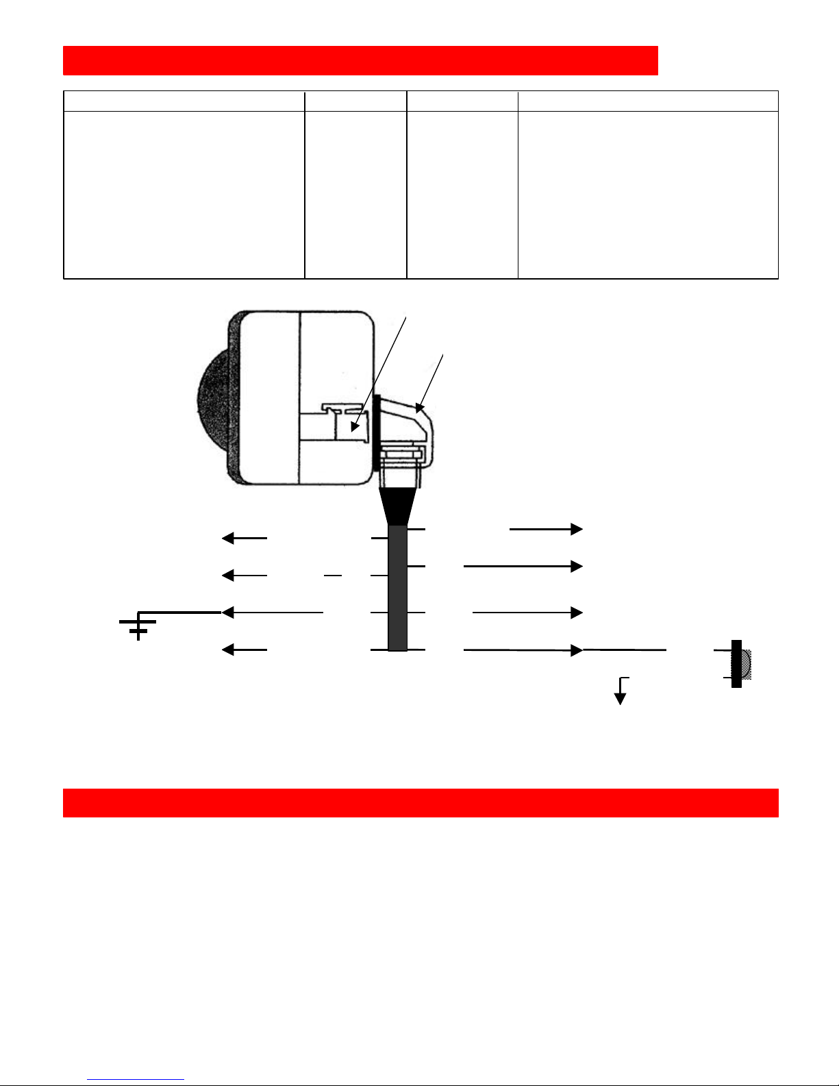
S230 / S231 - ELECTRICAL CONNECTIONSS230 / S231 - ELECTRICAL CONNECTIONS
function wire's colour specification examples for connection (explanation)
recognises application of ignition plus yellow-green (+15) +12 ±3V to be connected to ignition plus (+15)
supplies +12V to the alarm unit red (+30) +12 ±3V via 7,5A-fuse to battery-plus (+30)
ground connection of the alarm black (-31) ground to car's body, protect against oxidation
adaptation to the car's remote control yellow-white positive input to one of the direction indicator cables
recognises opening of doors grey-black negative input to the doors' ground-contact-switches
recognises opening of boot or bonnet pink negative input to the contact-switch of boot or bonnet...
surveillance by additional sensors violet negative input to the sensor's negative alarm output
supplies negative to supplementaries max. 0,2 A neg. to LED and to negative power-input of
as long as central locking is closed
}
{ output additional sensors, window closers,....
grey-black
pink
with black coating
violet
blue
black
red or white
+12V (+30)
red
black
yellow-white
yellow-green
ground contact
switches of doors * **
+15 ignition plus
+30 batterie plus
-31
ground
blinker
ground contact switch
of boot or bonnet *
negative alarm outputs
of additional sensors
installation
position
mount and fix the
device tightly,
far away from
heat sources,
mechanical
moving parts,
high voltage
elements, ....
NOTE:
*
ground contact switches supply
negative as long as door or boot is open.
NOTE: **Some cars require single connection
to each contact-switch, with each connection
to be separated by diode from the other
one of car's wires, that switches
by +12V a direction indicator
light to signal closing / opening
of central locking (thus enabling
now adaptation of the alarm to
the car's remote control)
blue
ADAPTATION OF ALARM TO CAR'S REMOTE CONTROLADAPTATION OF ALARM TO CAR'S REMOTE CONTROL
Page 3

..USER MANUALUSER MANUAL..
ARMING THE CAR ALARM
Close the car's central locking by its remote control.
The car alarm confirms by flashing LED (and by 3 beeps) to have been activated now.
After a inhibition time of 30 seconds the car alarm is armed.
FUNCTION TEST: During this inhibition time each surveillance sensor can be tested, since its
triggering (for example by opening door or bonnet) will be indicated by a beep.
IMPORTANT: It is not possible to arm the system, as long as the blinker (for example the
parking light function or emergency hazard) is switched on.
DISARMING THE CAR ALARM:
Open the car's central locking by its remote control.
The car alarm confirms by switching off its LED (and by 1 beep) to have been deactivated and
disarmed.
NOTE: Alarm-memory: In case the alarm has been triggered in an armed period (and not been
switched off by emergency key), this will be indicated now by a quicker 4 beep sequence
NOTE: A delay of 2 - 3 seconds between arming and disarming operations is advisable.
NOTE: In any case of emergency the car alarm can be disarmed by emergency key.
SWITCHING OFF THE SIREN-ALARM BY EMERGENCY KEY
In case alarm is triggered and siren is still signalling alarm, this siren sound can be switched off
only by switching OFF the car alarm by emergency key.
In order to disarm now the car alarm definitively, after switching it ON again by emergency key,
now open the car's central locking by its remote control.
Exclusion of beep signals: Reactivation of beep signals:
1. Switch OFF the car alarm by emergency key 1.Switch OFF the car alarm by emergency key
2. Switch ON ignition (+15) 2.Switch ON ignition (+15)
3. Switch ON the car alarm: 1 beep confirms 3.Switch ON the car alarm: 1 beep confirms
4. Switch OFF the car alarm: 1 beep confirms 4.Switch OFF the car alarm: 1 beep confirms
5. Switch ON the car alarm: 1 long beep confirms 5.Switch ON the car alarm: 1 long beep confirms
From now on, the arming and disarming From now on, the arming and disarming
will not be indicated by beep-signal. will be indicated again by beep signals.
© TOBÉ GmbH Aachen (10/2003) S230/S231 p.4/4
installation
date:
by:
TECHNICAL CHARACTERISTICS
activation and inhibition time 30 seconds
alarm duration 30 seconds
alarm cycles 10
recycling time 5 seconds
trigger delay 4 seconds
power consumption disarmed 7 mA
armed 11 mA
alarm triggered:0,8 A
power supply 12 V dc (±1V)
 Loading...