

Page 1

Medium Duty Counterline
INSTALLATION - OPERATION - MAINTENANCE
Griddle Models TMDG-24, TMDG-36
(shown) and TMDG-48
Charbroiler Models TMDC-24,
TMDC-36 (shown) and TMDC-48
Open Top Models TMDO-12,
TMDO-24 and TMDO-36 (shown)
Middleby Philippines Corporation
113 Technology Ave., Laguna Technopark Inc., Binan, Laguna, Philippines 4024
Phone (632) 5208170 - Fax (632) 5208191 - www.middleby.com
~
MANUAL MDC 0804-MDO-MDC
Page 2
SAFETY PRECAUTIONS
Before installing and operating this equipment, be sure everyone involved in its operation is fully trained and
aware of precautions. Accidents and problems can be caused by failure to follow fundamental rules and
precautions.
The following symbols, found throughout this manual, alert you to potentially dangerous conditions to the
operator, service personnel, or to the equipment.
DANGER
WARNING
CAUTION
NOTICE
This symbol warns of immediate hazards that will result in serve injury or death.
This symbol refers to a potential hazard or unsafe practice that could result in
injury or death.
This symbol refers to a potential hazard or unsafe practice that could result in
injury, product damage, or property damage.
This symbol refers to information that needs special attention or must be fully
understood, even though not dangerous.
WARNING
FIRE HAZARD
FOR YOUR SAFETY
Do not store or use gasoline or other flammable vapors and liquids in the vicinity of this or any
other appliance.
Keep area around appliances free and clear of combustibles.
Purchaser of equipment must post in a prominent location, detailed instructions to be followed in
the event the operator smells gas. Obtain the instructions from the local gas supplier.
Be sure this Operator’s Manual and important papers are given to the proper authority to retain
for future reference.
Toastmaster
WARNING
Asphyxiation can result from improper ventilation. Do not obstruct the flow of combustion and
ventilation air to and from your cooking equipment.
NOTICE
®
PAGE 2
Page 3
MEDIUM DUTY COUNTERLINE
Congratulations! You have purchased one of the finest pieces of commercial cooking equipment on the
market.
You will find that your new equipment, like all Toastmaster equipment, has been designed and manufactured to meet the toughest standards in the industry. Each piece of toastmaster equipment is carefully
engineered and designs are verified through laboratory tests and field installations. With proper care and
field maintenance you will experience years of reliable, trouble-free operation. For best results, read
this manual carefully.
TABLE OF CONTENTS
RETAIN THIS MANUAL FOR FUTURE REFERENCE.
Table of Contents
Specifications 4
Installation 9
Operation 12
Cleaning 14
Adjustments 16
Troubleshooting 18
Parts 21
Read these instructions carefully before attempting installation. Installation and initial startup should be
performed by a qualified installer. Unless the installation instructions for this product are followed by a
qualified service technician (a person experienced in and knowledgeable with the installation of commercial gas an/or electric cooking equipment) then the terms and conditions on the Manufacturer’s Limited
Warranty will be rendered void and no warranty of any kind shall apply.
In the event you have questions concerning the installation, use, care, or service of the product, write to:
MIDDLEBY COOKING SYSTEM
Philippine Factory : 113 Technology Ave., Laguna Technopark, Binan
Laguna, Philippines, 4024 * Tel. Nos. (632) 520-8170 to 79 Fax No.: (632) 520-8191
USA Factory : 1400 Toastmaster Drive, Elgin, IL 60120 Tel. (847) 741-3300
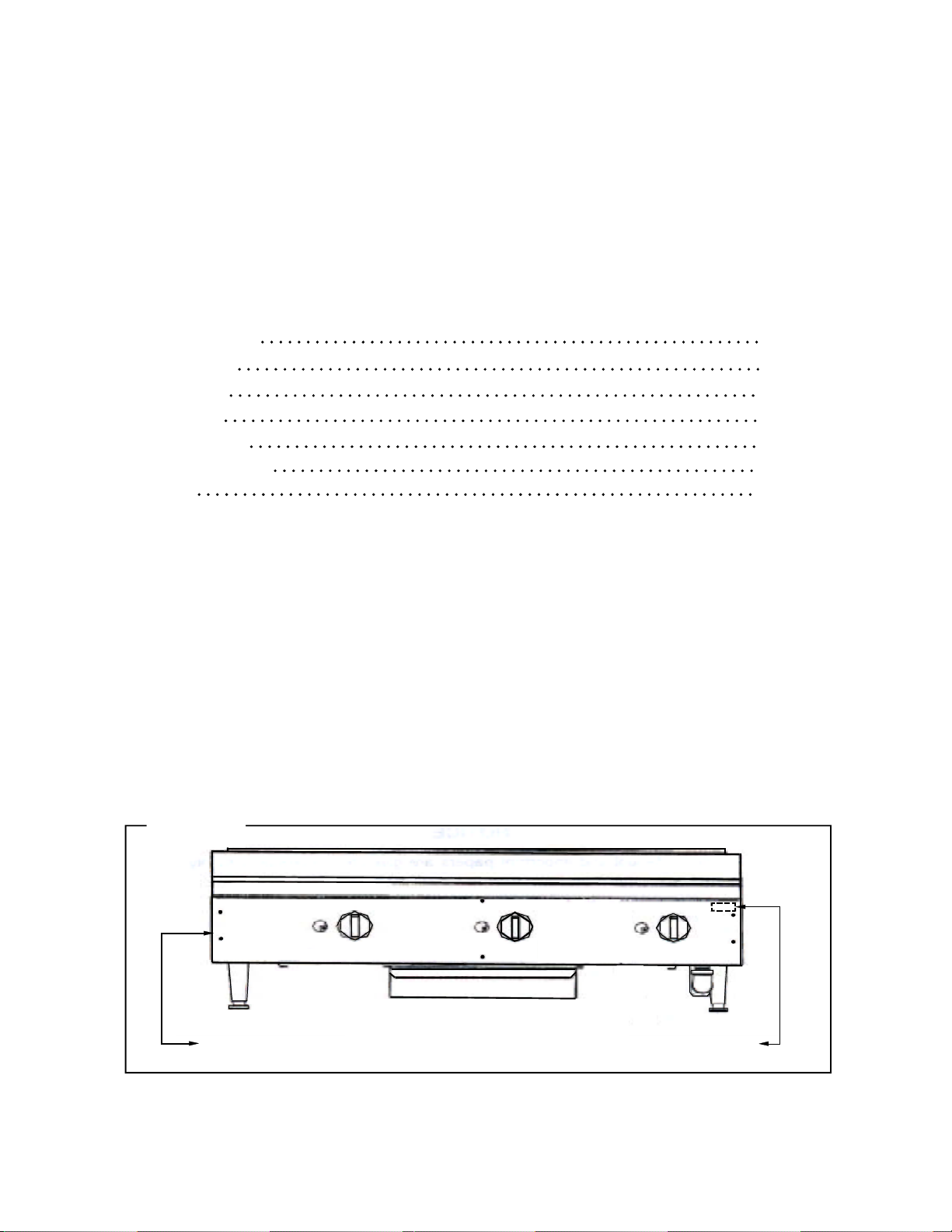
The serial plate is located on the interior side of the valve panel, as shown below:
~
Figure 1
PAGE3
Serial plate is located on the outer left side and upper right side of front panel
Toastmaster
®
Page 4
SPECIFICATIONS
MEDIUM DUTY COUNTERLINE
SPECIFICATIONS
NOTICE
Installation must comply with National Fuel Gas Code, ANSI Z223.1, Natural Gas Installation Code,
CAN/CGA-B149.1, or the Propane Instalation Code, CAN/CGA-B149.2, as applicable.
Local codes regarding installation vary greatly from one area to another. The National Fire Protection Association, Inc. states in its NFPA 96 latest edition that local codes are the “authority” having
jurisdiction” when it comes to installation requirements for equipment. Therefore, installations should
comply with all locals codes.
Toastmaster reserves the right to change specifications and product design without notice. Such
revisions do not entitle the buyer to corresponding changes, additions, or replacements for previously purchased equipment.
This product is intented for commercial use only, not for household use.
GAS SUPPLY
The Serial Plate is located on the interior side of the valve panel (see Figure 1 on page 3). It indicates the
type of gas the unit is equipped to burn. All Toastmaster equipment is adjusted at the factory. Check type
of gas on serial plate.
These models are design-certified for operation on natural or propane gases. The unit is shipped configured for natural gas. A kit for conversion to using propane gas is included (see instructions in kit or page 9
of this manual).
This appliance should be connected ONLY to the type of gas for which it is configured.
An adequate gas supply is imperative. Undersized or low pressure lines will restrict the volume of gas
required for satisfactory performance. Fluctuations of more than 25% on natural gas or 10% on propane
gas will create problems and affect burner operating characteristics. A 1/8” pressure tap is located on the
manifold to measure the manifold pressure.
An adequate gas supply line to the unit should be no smaller than the inside diameter of the pipe from the
unit to which it is connected.
Purge the supply line to clean out dust, dirt, or other foreign matter before connecting the line to the unit.
All pipe joints and connections must be tested thoroughly for gas leaks. Use only soapy water for testing
on all gases. NEVER use an open flame to check for gas leaks. All connections must be checked for
leaks after the unit has been put into operation. Test pressure should not exceed 14” W.C.
CAUTION
THIS APPLIANCE AND ITS INDIVIDUAL SHUTOFF VALVE MUST BE DISCONNECTED FROM
THE GAS SUPPLY PIPING SYSTEM DURING ANY PRESSURE TESTING OF THAT SYSTEM
AT TEST PRESSURES IN EXCESS OF 1/2 PSIG (3.45 kPa).
THIS APPLIANCE MUST BE ISOLATED FROM THE GAS SUPPLY PIPING SYSTEM BY CLOSING ITS INDIVIDUAL MANUAL SHUTOFF VALVE DURING ANY PRESSURE TESTING OF THE
GAS SUPPLY PIPING SYSTEM AT TEST PRESSURES EQUAL TO OR LESS THAN 1/2 PSIG
(3.45 kPa).
SPECIFICATIONS
Toastmaster
®
PAGE 4
Page 5
MEDIUM DUTY COUNTERLINE
SPECIFICATIONS
CLEARANCES
WARNING
There must be adequate clearance between units and adjacent construction. Clearance must also
be provided for servicing and for operation.
Minimum Clearances from COMBUSTABLE construction:
Griddle Models Open Top Models
Sides 4” 6”
Back 4” 6”
Bottom 4” 6”
Minimum Clearances from NON-COMBUSTABLE construction:
Griddle Models Charbroiler Models Open Top Models
Sides 0” 4” 0”
Back 0” 4” 0”
Bottom 4” 4” 4”
VENTILATION
WARNING
Improper ventilation can result in personal injury or death. Ventillation which fails to propely remove
flue products can cause headaches, nausea, or could result in death.
All units must be installed in such a manner that the flow of combustion and ventilation air are not
obstructed. Provisions for adequate air supply must be provided. Do not obstruct the front of the
unit at the top by the control panel as combustion air enters these areas.
NOTICE
Proper ventillation is the owner’s responsibility. Any problem due to improper ventilation will not be
covered by the warranty.
All units must be installed in such a manner that the flow of combustion and ventillation air are not obstructed. Provisions for an adequate air supply must be provided. Do not obstruct the front or rear of the
unit, as combustion air enters through this area. Be sure to inspect and clean the ventillation system
according to the ventillation equipment manufacturer’s instruction.
In case of unsatisfactory performance on any appliance, check the appliance with the hood exhaust fan in
the “OFF” position. Do this only long enough to check equipment performance. Then turn the fan back on
and left it run to remove any exhaust that may have accumulated during the test.
SPECIFICATIONS
PAGE 5
Toastmaster
®
Page 6
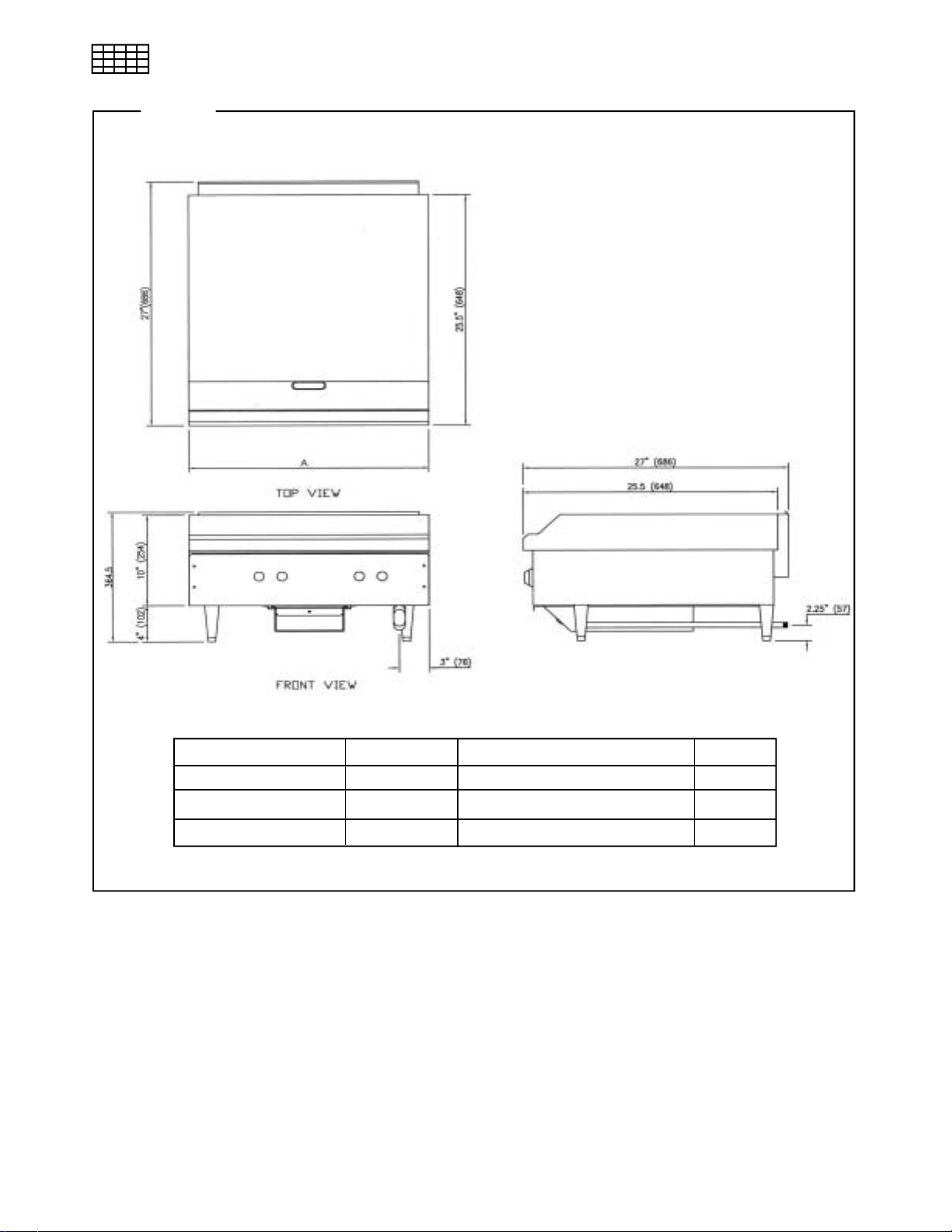
SPECIFICATIONS
Figure 2
DIMENSIONS OF GRIDDLE
MEDIUM DUTY COUNTERLINE
Toastmaster
TMDG-24
TMDG-36
TMDG-48
®
Model
“A” (Width) Number and Size of Burners
24”
36”
48”
2@30,000
3@30,000
4@30,000
Total BTU
60,000
90,000
120,000
SPECIFICATIONS
PAGE 6
Page 7
MEDIUM DUTY COUNTERLINE
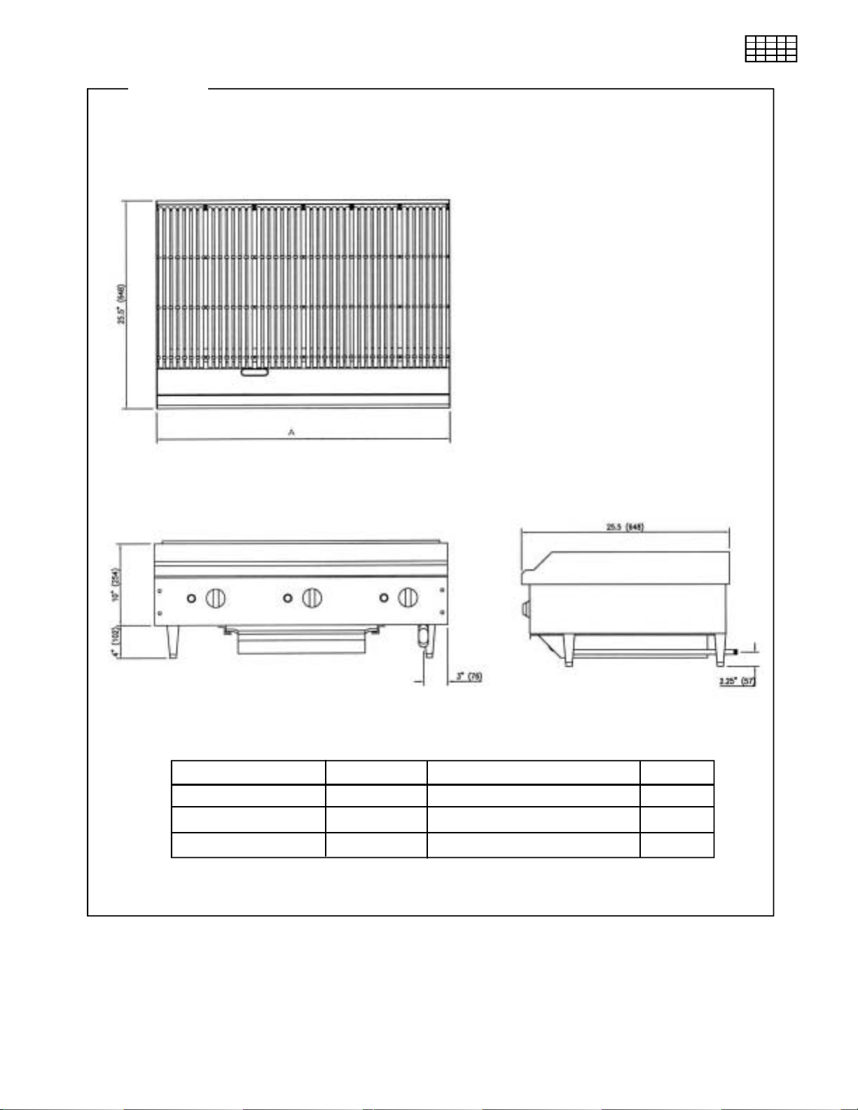
Figure 3
DIMENSIONS OF CHARBROILER MODELS
SPECIFICATIONS
SPECIFICATIONS
PAGE 7
Model
TMDC-24
TMDC-36
TMDC-48
“A” (Width) Number and Size of Burners
24”
36”
48”
2@30,000
3@30,000
4@30,000
Total BTU
60,000
90,000
120,000
Toastmaster
®
Page 8
SPECIFICATIONS
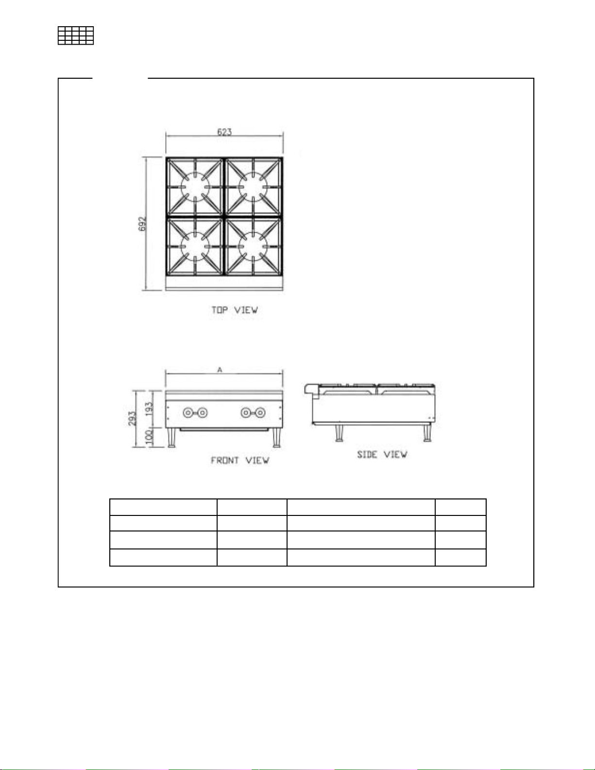
Figure 4
DIMENSIONS OF OPEN TOP MODELS
MEDIUM DUTY COUNTERLINE
Toastmaster
Model
TMDO-12
TMDO-24
TMDO-36
“A” (Width) Number and Size of Burners
12.25”
24.375”
36.50”
2@20,000
4@20,000
6@20,000
Total BTU
40,000
80,000
120,000
SPECIFICATIONS
®
PAGE 8
Page 9

EDIUM DUTY COUNTERLINE
M
Installation
INSTALLATION
NOTICE
Installation must comply with National Fuel Gas Code, ANSI Z223.1, Natural Gas Installation Code,
CAN/CGA-B149.1, or the Propane Instalation Code, CAN/CGA-B149.2, as applicable.
These installation procedures must be followed by qualified personnel or warranty will be void.
Local codes regarding installation vary greatly from one area to another. The National Fire Protection Association, Inc. states in its NFPA 96 latest edition that local codes are the “authority having
jurisdiction” when it comes to installation requirements for equipment. Therefore, installations should
comply with all locals codes.
Step 1: Unpack
IMMEDIATELY INSPECT FOR SHIPPING DAMAGE
All containers should be examined for damage before and during unloading. The freight carrier has
assumed responsibility for its safe transit and delivery. If damaged equipment is received, either
apparent or concealed, a claim must be made with the delivering carrier.
Apparent damage or loss must be noted on the freight bill at the time of delivery. The freight bill must
then be signed by the carrier representative (Driver). If the bill is not signed, the carrier may refuse
the claim. The carrier can supply the necessary forms.
A request for inspection must be made to the carrier within 15 days if there is concealed damage or
loss that is not apparent until after the equipment is uncrated. The carrier should arrange an inspection. Be certain to hold all contents plus all packing material.
1. Uncrate carefully. Report any hidden damage to the freight carrier IMMEDIATELY.
2. Do not remove any tags or labels until unit is installed and working properly.
Step 2: Convert Unit to Use Propane Gas (if necessary)
Each unit is shipped equipped with fixed orifice hoods appropriate for use with natural gas. If propane gas
will be used, convert the unit for use with propane gas by the following procedure:
1. Remove the front panel by removing the knobs and screws on the front.
2. For charbroiler and open top models, remove the grates and burners to access the orifices from
above. For griddle models, slide the burner toward the rear of the unit to access the orifices (see
diagram on page 22), OR remove the griddle plate to access the orifices by removing two nuts at the
rear of the unit.
3. Remove the natural gas orifices and install the furnished propane orifices.
4. Re-install the burners.
5. Re-install the front panel.
6. Remove the hex-threaded plug from the pressure regulator. Inside is a removable insert. Pull the
insert out, turn it around, and put it back in so that the end with the letters “LP” is now facing you.
INSTALLATION
Re-attach the hex-threaded plug. The pressure regulator is now set for 10” (25.4cm) water column.
7. Check the pressure.
PAGE 9
Toastmaster
®
Page 10

INSTALLATION
Provided orifices are size #45 for natural gas and #55 for propane gas. For special gas mixtures, and for
altitudes above 2,000 feet, consult factory for appropriate orifice sizes.
MEDIUM DUTY COUNTERLINE
Step 3: Connect Gas Supply
All units are shipped from the factory equipped for use with natural gas. If the unit is to be used
with propane gas, the orifices must be replaced and the pressure regulator converted (see Step
2 on previous page).
If this equipment is being installed at over 2,000 feet altitude and that information was not specified when
ordered, contact the appropriate authorized Toastmaster Service Representative of the Toastmaster Service Department. Failure to install with proper orifice sizing in poor performance and may void the warranty.
The Serial Plate is located on the interior side of the valve panel (see Figure 1 on page 3). It indicates the
type of gas the unit is equipped to burn. All Toastmaster equipment is adjusted at the factory. Check type
of gas on serial plate.
These models are design-certified for operation on natural or propane gases. For natural gas,
the convertible regulator is set to deliver a 4”W.C. pressure to the manifold. For propane gas, it
is set to deliver 10” W.C.
If applicable, the vent line from the gas appliance pressure regulator shall be installed to the outdoors in
accordance with local codes or, in the absence of local codes, with the National Fuel Gas Code, ANSI
Z223.1, Natural Gas Installation Code, CAN/CGA-B149.1, or the Propane Installation Code, CAN/CGAB149.2, as applicable.
This appliance should be connected ONLY to the type of gas for which it is equipped.
An adequate gas supply is imperative. Undersized or low pressure lines will restrict the volume of gas
required for satisfactory performance. Fluctuations of more than 25% on natural gas or 10% on propane
gas will create problems and affect burner operating characteristics. A 1/8” pressure tap is located on the
manifold to measure pressure.
An adequate gas supply line to the unit should be no smaller than the I.D. of the pipe from the unit to which
it is connected.
Purge the supply line to clean out dust, dirt, or other foreign matter before
Use pipe joint compound that is suitable for use with LP gas on all threaded connections.
connecting the line to the unit.
CAUTION
ALL PIPE JOINTS AND CONNECTIONS MUST BE TESTED THOROUGHLY FOR GAS LEAKS.
USE ONLY SOAPY WATER FOR TESTING ON ALL GASES. NEVER USE AN OPEN FLAME
TO CHECK FOR GAS LEAKS. ALL CONNECTIONS MUST BE CHECKED FOR LEAKS AFTER THE UNIT HAS BEEN PUT INTO OPERATION. TEST PRESSURE SHOULD NOT EXCEED 14” W.C.
Step 4: Position Unit for Operation
1. Check that the unit is level. The length of each leg is adjustable by screwing the bottom portion of the
leg in or out. The unit must be level for proper operation!
INSTALLATION
2. Check for adequate clearances around the unit (see page 5).
3. Check for adequate ventilation (see page 5).
Toastmaster
®
PAGE 10
Page 11

M
EDIUM DUTY COUNTERLINE
Installation
Step 5: Adjust Air Shutters and Pilot Heights
All units are adjusted at the factory. However, burner air shutters and pilot heights should be checked at
installation and adjusted if necessary. On new installations, start with the burner of the unit(s) furthest from
the gas input to the manifold. This will purge the system of air.
1. Turn main gas supply “ON”.
2. Follow the instructions on pages 12 to 13 light the pilots and burners.
3. If the burner flame is strong but lifting from the burner, loosen the screw on the air shutter and close
the shutter a little at a time until the flame settles back onto the burner.
Step 6: Condition Griddle Surface
For griddle and thermostatic-griddle models, the new griddle surface should be carefully tempered and
cared for in order to avoid possible damage. To break in a new griddle, first wipe it clean. Next, light all the
griddle burners and turn them to low for one hour. Then gradually bring each griddle up to frying temperature. Next, spread three or four ounces of beef suet, or as a substitute, baking soda, to season it. Never
allow water on a hot griddle and never wash it with soap and water.
INSTALLATION
PAGE 11
Toastmaster
®
Page 12

OPERATION
MEDIUM DUTY COUNTERLINE
OPERATION
DANGER
EXPLOSION HAZARD
Purchaser of equipment must post in a prominent location, detailed instructions to be followed in the
event the operator smells gas. Obtain the instructions from the local gas supplier.
CAUTION
To eliminate gas build up which could result in an explosion, in the event of main burner ignition failure
a five minute purge period must be observed prior to re-establishing ignition source.
CAUTION
Top section pilots, when out, do not interrupt the flow of gas to the burners. Consequently, it is the
responsibility of the operator to check the ignition of the burners, immediately after burner value has
been turned “ON”. Should ignition fail after 10 seconds, turn off burners, wait 5 minutes, and then try
again.
LIGHTING AFTER GAS HAS BEEN SHUT OFF
When turning the main gas supply on after the gas supply has been shut off, do the following:
1. Make sure all of the control valves are in the “OFF” position.
2. Turn on the gas supply.
3. Light the pilots as described below.
GRIDDLE
Each 12”-wide griddle section has a knob on the front panel that directly controls the flow of gas, and so the
heat. Turn the knob clockwise to increase the heat; turn it counterclockwise to reduce the heat.
At the end of each day’s use, turn all knobs to the “OFF” position. After each period of use, allow the griddle
surface to cool normally. After the griddle has cooled, coat the griddle surface with a light film of cooking oil
to protect the surface from moisture.
To light the pilot of a griddle section, do the following:
1. Turn all control knobs to the “OFF” position.
2. Light the pilot tube located next to each burner. The pilot flame can be adjusted by turning the screw
on the end of the pilot fitting.
3. Turn burner knobs to “HI” position. The burners should have a 1/2” to 5/8” steady blue flame. Adjust
if necessary.
OPERATION
4. To turn burners off, turn knob to “OFF” position.
Toastmaster
®
PAGE 12
Page 13
MEDIUM DUTY COUNTERLINE
OPERATION
CHARBROILERS MODELS
Each 12”-wide charbroiler section has a knob on the front panel that directly controls the flow of gas,
and so the heat. Turn the knob clockwise to increase the heat; turn it counterclockwise to reduce the
heat.
At the end of each day’s use, turn all knobs to the “OFF” position.
To light the pilot of a charbroiler section, do the following:
1. Turn all control knobs to the “OFF” position.
2. Light the pilot tube located next to each burner. The pilot flame can be adjusted by turning the screw
on the end of the pilot fitting.
3. Turn burner knobs to “HI” position. The burners should have a 1/2” to 5/8” steady blue flame. Adjust
if necessary.
4. To turn burner’s off, turn knob to “OFF” position.
OPEN-TOP BURNER MODELS
Each 12”-wide open-top burner section has two knobs on the front panel that directly control the flow of
gas to the section’s two burners, and so control the heat. Turn a knob clockwise to increase the heat;
turn it counterclockwise to reduce the heat.
At the end of each day’s use, turn all knobs to the “OFF” position.
To light the pilots of an open-top burner section, do the following:
1. Turn all gas valves to the “OFF” position.
2. Check to make sure pilots are in the correct position.
3. Light the pilots.
4. Adjust the pilot flame as necessary.
5. Turn burner knobs to “HI” position. Each burner flame should be steady blue and impinge on the
underside of a pot placed on the support grate. Adjust if necessary.
6. To turn burners off, turn knob to “OFF” position.
OVERNIGHT SHUTDOWN
Turn knobs to the OFF” position to turn the burners off.
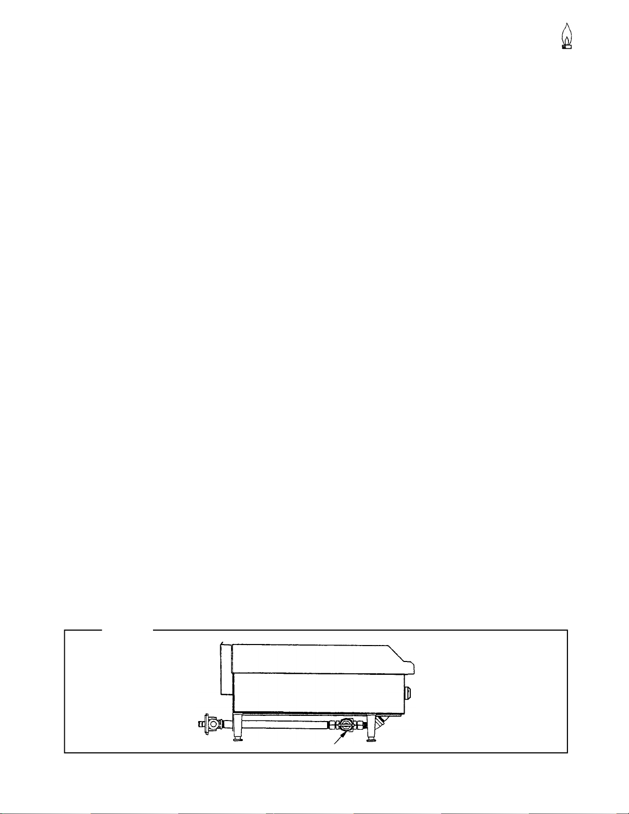
Figure 5
OPERATION
PAGE 13
Main Gas Supply Valve
Toastmaster
®
Page 14

CLEANING
MEDIUM DUTY COUNTERLINE
CLEANING
Toastmaster equipment is constructed with the best quality materials and is designed to provide durable
service when properly maintained. To expect the best performance, your equipment must be maintained
in good condition and cleaned daily. Naturally, the frequency and extent of cleaning depends on the amount
and degree of usage.
EXTERIOR AND TOP SECTIONS:
1. Keep exposed, cleanable areas of unit clean at all times.
Daily:
A. Remove, empty, and clean grease drawers and dirt trays.
B. Clean griddle drain chutes.
Monthly:
A. Clean around burner air mixers and orifices if lint has accumulated.
B. Visually assure proper pilot operation.
STAINLESS STEEL SURFACES
1. To remove normal dirt, grease and product residue from stainless steel that operates at LOW
temperature, use ordinary soap and water (with or without detergent) applied with a sponge or
cloth. Dry thoroughly with a clean cloth.
2. To remove grease and food splatter, or condensed vapors, that have BAKED on the equipment, apply
cleanser to a damp cloth or sponge and rub cleanser on the metal in the direction of the polishing lines
on the metal. Rubbing cleanser, as gently as possible, in the direction of the polished lines will not
mark the finish of the stainless steel. NEVER RUB WITH A CIRCULAR MOTION. Soil and burnt
deposits which do not respond to the above procedure can usually be removed by rubbing the surface
with SCOTCH-BRITE scouring pads or STAINLESS scouring pads. DO NOT USE ORDINARY STEEL
WOOL, as any particles left on the surface will rust and further spoil the appearance of the finish.
NEVER USE A WIRE BRUSH, STEEL SCOURING PADS (EXCEPT STAINLESS), SCRAPPER, FILE
OR OTHER STEEL TOOLS. Surfaces which are marred collect dirt more rapidly and become more
difficult to clean. Marring also increases the possibility of corrosive attack. Refinishing may then be
required.
3. To remove heat tint - Darkened areas sometimes appear on stainless steel surfaces where the area
has been subjected to excessive heat. These darkened areas are caused by thickening of the
protective surface of the stainless steel and are not harmful. Heat tint can normally be removed by
the foregoing, but tint which does not respond to this procedure calls for a vigorous scouring in the
direction of the polish lines, using SCOTCH-BRITE scouring pad in combination with a powered
cleanser. Heat tint action may be lessened by not applying, or by reducing heat to equipment during
slack periods.
BURNERS - GENERAL
Little attention is needed, but if spillage should occur, it may be necessary to clean around pilot areas, air
mixer and under burners. Use a wire brush if necessary.
Periodically, burners (particularly open top type) should be removed and cleaned. Allow interior to drain.
Dry thoroughly before replacing.
Toastmaster
®
CLEANING
PAGE 14
Page 15

MEDIUM DUTY COUNTERLINE
CLEANING
CARE OF GRIDDLES
New griddles should be carefully tempered and cared for in order to avoid possible damage. To break in a
new griddle, first wipe it clean. Next, light all the griddle burners and turn them to low for one hour. Then
gradually bring each griddle up to frying temperature. Next, spread three or four ounces of beef suet, or as
a substitute, baking soda, to season it. Never allow water on a hot griddle and never wash it with soap and
water.
Use a Norton Alundum Griddle Brick to clean the griddle. Always remember to heat griddle slowly because
quick heat may cause costly damage. Griddle plates cannot be guaranteed against damage due to
carelesness. Never place utensils on griddle. Do not overheat griddle above 550°F, as this will cause
warpage or breakage.
Do not use any type of steel wool. Small particles may be left on the surface and get into food products.
Do not clean spatula by hitting the edge on the griddle plate. Such action will only cut and pit the griddle
plate, leaving it rough and hard to clean.
Do not waste gas or abuse equipment by leaving valves at “Full On” position or thermostat at a high
temperature if not required. During idle periods, set valves at “Low” position or thermostats to low temperature settings to keep griddle warm. Reset valves or thermostats, as required, for periods of heavy
load. Turn valves or thermostats to “OFF” at end of daily operation.
CLEANING
PAGE 15
Toastmaster
®
Page 16
ADJUSTMENTS
MEDIUM DUTY COUNTERLINE
ADJUSTMENTS
WARNING
ADJUSTMENTS AND SERVICE WORK MAY BE PERFORMED ONLY BY A QUALIFIED
TECHNICIAN WHO IS EXPERIENCED IN, AND KNOWLEDGEABLE WITH, THE OPERATION OF
COMMERCIAL COOKING EQUIPMENT. HOWEVER, TO ASSURE YOUR CONFIDENCE,
CONTACT YOUR AUTHORIZED SERVICE AGENCY FOR RELIABLE SERVICE, DEPENDABLE
ADVICE OR OTHER ASSITANCE, AND FOR GENUINE FACTORY PARTS.
In case of problems in operation at initial installation, check type of gas and manifold pressure and compare with information listed on the serial plate.
GAS PRESSURE REGULATOR
The convertible pressure regulator is factory set at 4”W.C. for natural gas. (To convert for use with propane
gas (10”W.C.), follow the procedure on page 9). To check the manifold pressure:
1. Turn all burner gas valve to “OFF” position.
2. Turn main gas valve to entire unit off.
3. Remove front panel and locate 1/8” plug in manifold.
4. Remove plug and install a fitting appropriate to connect a manometer.
5. Turn on main gas to unit and light pilots.
6. Turn all burners and ovens to full “ON” position and read manometer.
7. If manometer does not read 4”W.C. for natural gas (or 10”W.C. for propane gas), check the incoming
gas line for proper pressure.
8. Remove manometer fitting and replace plug in manifold.
9. Repeat step 5.
10. Replace front panel.
TOP PILOTS: NON-AERATED (YELLOW-TIPPED FLAME) TYPE
Outage is often caused by an unstable flame due to over-adjustment to the point where the flame is leaving
its port, or “blowing off”.
Often, in an effort to improve ignition, the pilots are increased too much and result in this unstable condition.
These pilots are adjusted by inserting the blade of a screwdriver into the slot on the small valve, located on
the manifold. The maximum flame size is approximately 3/4” with a slight yellow tip. The first indication of
over-adjustment is evident when the yellow tip begins to stream into black streaks and generate carbon.
Continued over-adjustment leads to the unstable lifting and blowing condition.
ADJUSTMENTS
ALL TOP BURNERS
All burners have a primary air adjustment by means of an air shutter on the mixer face.
Loosen screw and rotate mixer cap until a clear, stable blue flame is obtained. The flame should not be
yellow tipped nor should it blow off the burner ports.
Toastmaster
®
PAGE 16
Page 17

MEDIUM DUTY COUNTERLINE
ADJUSTMENTS
All orifices sizes and burner rate are properly set at the factory and should not be altered.
Over-rated burners cause poor burner and pilot performance, resulting in less heat, and wasted gas.
Over-gassed burners DO NOT heat griddles as those that are properly adjusted. Such conditions also
create “hot spots” on griddles. Floating and unstable burner and pilot flames will result when solid tops are
lowered into position because the rear openings of the burner compartment are not adequate to vent the
enormous flue products generated by over-gassed burners. The “unburned” gas will ignite at the rear and
burn in this section and even up inside the backguard or shelf venting system, causing structural members
in this area to deteriorate. Also, some of these hot flue products will vent forward into the manifold compartment resulting in problems with valves and thermostats due to overheating. AGAIN, over-rated burners
waste energy and cause service problems.
ADJUSTMENTS
PAGE 17
Toastmaster
®
Page 18

TROUBLESHOOTING
MEDIUM DUTY COUNTERLINE
TROUBLESHOOTING
Consult the following table and the flowchart that begins on the following page.
Problem Look for
All burners and pilots in unit will not turn on -Main gas supply to unit is “OFF”
All burners produce excessive carbon deposits -Incorrect gas type supplied to unit.
-Incorrect supply pressure.
Only some burners in a unit produce excessive -Incorrect orifices.
carbon deposits -Primary air not adjusted properly.
Only some pilots produce excessive carbon -Pilot gas not adjusted properly.
deposits -Incorrect pilot office.
Top burner will not come on -Manual valve for top burner in “OFF”
position
-Pilot out.
Top section pilot will not stay ignited -Pilot gas not adjusted properly
-Clogged orifice.
-Draft condition.
-Improper ventilation system.
-Air in gas line.
TROUBLESHOOTING
Toastmaster
®
PAGE 18
Page 19

MEDIUM DUTY COUNTERLINE
Common checks for all top
configurations.
TROUBLESHOOTING
OPEN TOP BURNER
TROUBLESHOOTING.
NOTE : Griddle Tops
Check that the burners are set
level in the support brackets.
Check that the burners are
clean and all ports are clear.
Remove each burner and check
that the venturi is clean and free
of buildup and debris.
With each burner removed check that
the orifice size is correct and clean and
free of buildup and debris.
Remove the knobs and carefully
lower the top valve cover panel.
Check that each burner valve and
orifice is in alignment with the burner.
Shut off the main gas supply.
NOTE : Griddle must be raised
and secured or removed.
CAUTION! Before raising or
removing Griddle Tops.
Remove the knobs and carefully
lower the top valve cover panel.
Observe the inlet
pressure.
Install a pressure tap in the main gas line
before the range pressure regulator and
install a manometer.
Turn on the main gas supply.
Re-light all pilots.
Light all burners on the range.
TROUBLESHOOTING
PAGE 19
Inlet pressures for gases are:
Natural = 5 to 7 in. water column
Propane = 11 to 14 in. water column
If the inlet pressure is low, all equipment
on the main gas line should be lit and the
pressure adjusted.
Shut off the range burners and
main gas and remove the
pressure tap.
Continue on next page.
Toastmaster
®
Page 20

TROUBLESHOOTING
Continued from
Previous Page
With the gas supply shut off,
install a pressure tap on the
manifold in the plugged tap
provided.
Install a manometer
on the pressure tap.
Turn on the gas
supply to the range.
MEDIUM DUTY COUNTERLINE
Re-light the pilots and turn
on all the burners.
Observe the manifold
pressure.
Manifold pressure are:
Natural gas = 4 in. water column
Propane gas = 10 in. water column
If the pressure is low, check the
incoming line for obstructions.
Shut off the burners and main gas
and remove the pressure tap.
Replace the pressure tap
plug in the manifold.
Test each burner.
Each burner should have a
steady blue flame on each port
of the burner.
Propane burners may have a small
amount of yellow tipping. This is normal.
If the flame is rising up off of the ports
adjust the burner shutter closed.
If the flame is long and yellow
adjust the burner shutter open.
NOTE : Griddle burners may
be long and float when cold.
Allow the top to heat before
making burner adjustments.
TROUBLESHOOTING
Toastmaster
Re-light the pilots.
Install the grates or
griddle tops.
®
Propane burners may have a
slight popping noise when
turned off. This is normal.
Reinstall the front
panel and knobs.
PAGE 20
Page 21

MEDIUM DUTY COUNTERLINE
PARTS
PARTS
NOTICE
INSTALLATION OF OTHER THAN GENUINE TOASTMASTER PARTS WILL VOID THE
WARRANTY ON THIS EQUIPMENT.
The serial plate is located inside of the front panel (see Figue 1 and page 3).
Replacement parts may be ordered either through a Toastmaster Authorized Parts Distributor or a Toastmaster Authorized Service Agency.
When ordering parts, please supply the Model Number, Serial Number, Part Number, and Description.
For parts not listed, consult a Toastmaster Authorized Parts Distributor or Toastmaster Authorized Service
Agency. Consult the Toastmaster authorized Parts/Service Distributor list for the Authorized Parts supplier in your area. If this list is not available, call Toastmaster at (847) 741-3300 to obtain this list.
Index of Parts Diagrams
Page Number
22
22
24
Description
Parts for Griddle Models TMDG-24, TMDG-36 and TMDG-48
Parts for Charbroiler Models TMDC-24, TMDC-36 and TMDC-48
Parts for Open-Top Models TMDO-12, TMDO-24 and TMDO-36
PARTS
PAGE 21
Toastmaster
®
Page 22

PARTS
Medium Duty Counterline /Medium Duty Griddle
1
3
4
MEDIUM DUTY COUNTERLINE
2
8
12
13
5
6
10
7
Toastmaster
9
11
14
15
PARTS
®
PAGE 22
Page 23

MEDIUM DUTY COUNTERLINE
PILOT 020 PROP.
KNOB, CONTROL
Medium Duty Counterline /Medium Duty Griddle
QUANTITY
Key Part Number 24 36 48 Description
1 S1146910 1 1 1 ELBOW STREET BLK 3/4"
2 S1178815 1 1 1 REGULATOR, PRESSURE (N/LP)
3 S1038099 2 3 4
4 S1178816 2 3 4 EXTENSION PILOT
5 S1008755 2 3 4 ORIFICE #55, (1.32) BRASS LP
1850351 2 3 4 ORIFICE #45, (2.08) BRASS NAT.
6 S1178821 2 3 4 VALVE, PILOT ADJUSTING
7 S1177704 2 3 4
8 1800205 1 POLYPANEL MDC/MDG 24"
1800206 1 POLYPANEL MDC/MDG 36"
1800207 1 POLYPANEL MDC/MDG 48"
9 S1178202 2 3 4 VALVE, HI-OFF NAT/LP
10 1100439 1 1 1 PIPE, BI 3/4" X 20" SCH 80
11 1100059 1 1 1 NIPPLE, BI, 3/4" X 2
12 1850318 1 MANIFOLD MDC/MDG 24"
1850186 1 MANIFOLD MDC/MDG 36"
1850187 1 MANIFOLD MDC/MDG 48"
13 S1147007 1 1 1 PLUG, PIPE BLK, 1/8"
14 1952678 2 3 4 BURNER (U) DOUBLE HOLES
15 S1172857 1 1 1 LEGS SET OF 4/CMS,2001
PARTS
PARTS
PAGE 23
Toastmaster
®
Page 24

PARTS
Medium Duty Counterline Open Top
3
4
1
5
2
MEDIUM DUTY COUNTERLINE
10
12
8
11
9
12
13
14
7
Toastmaster
16
15
17
18
PARTS
®
PAGE 24
Page 25

MEDIUM DUTY COUNTERLINE
Medium Duty Counterline Open Top
QUANTITY
Key Part Number 12 24 36 Description
1 1850303 1 2 3 PILOT TUBE FRONT MDO
2 1850304 1 2 3 PILOT TUBE REAR MDO
3 S1008755 2 4 6 ORIFICE #55, (1.32) BRASS LP
S1008745 2 4 6 ORIFICE # 45, (2.08) BRASS NAT.
4 S1178202 2 4 6 VALVE, HI-OFF NAT/LP
5 S1177704 2 4 6 KNOB, CONTROL
6 S1177111 1 2 3 BURNER ASSEMBLY 26K SHO
7 S1177439 1 2 3 BURNER CAST REAR 400C
8 1850128 2 4 6 PILOT LIGHT 20 OD X 17 L
9 S1147007 1 1 1 PLUG, PIPE BLK, 1/8"
10 1850307 1 MANIFOLD MDO 12"
1850319 1 MANIFOLD MDO 24"
1850202 1 MANIFOLD MDO 36"
11 S1178944 1 1 1 TAIL PIPE MDO
12 S1166004 1 2 3 FITTING DOUBLE PILOT 3/16
13 S1146904 1 1 1 ELBOW BLK 3/4" 90 DEGREE
14 S1181100 2 4 6 GRATE COUNTER TOP
15 1146910 1 1 1 ELBOW STREET BLK 1/8"
16 S1178815 1 1 1 REGULATOR PRESSURE (N/LP)
17 S1172857 1 1 1 LEGS SET OF 4/CMS,2001
18 1800198 1 POLYPANEL MDO 12"
1800208 1 POLYPANEL MDO 24"
1800209 1 POLYPANEL MDO 36"
PARTS
PARTS
PAGE 25
Toastmaster
®
Page 26

MEDIUM DUTY COUNTERLINE
A product with the Toastmaster name incorporates the best in durability and low maintenance. We
all recognize, however, that replacement parts and occasional professional service may be necessary to extend the useful life of this unit. When service is needed, contact a Toastmaster Authorized Service Agency, or your dealer. To avoid confusion, always refer to the model number. Serial
number, and type of your unit.
Toastmaster
Philippine Factory : 113 Technology Ave., Laguna Technopark, Binan
Laguna, Philippines, 4024 * Tel. Nos. (632) 520-8170 to 79 Fax No.: (632) 520-8191
USA Factory : 1400 Toastmaster Drive, Elgin, IL 60120 Tel. (847) 741-3300
MANUAL MDC0804-MDO-MDC
®
~
 Loading...