

Page 1
Place this chapter in the Toaster
TABLE OF CONTENTS
WARRANTY
1 WARNINGS
&
CAUTIONS
2
INTRODUCTION
3
SPECIFICATION CHART
3
INSTALLATION
4
PARTS IDENTIFICATION AND FUNCTION
6-7
EQUIPMENT SET
-
UP AND CLOSE PROCEDURES
9
TROUBLESHOOTING
10-11
ORDERING AND SERVICE INFORMATION
11
NON
-
SCHEDULED MAINTENANCE
12-17
Section of your Equipment Manual
MANUFACTURED
EXCLUSIVELY FOR
McDONALD'S®
By
Toastmaster®
A Middleby Company 1400
Toastmaster Drive Elgin, IL
60120 (847)741-3300 FAX (847)
741-4406 Middleby Corp 24 Hour
Service Hotline 1-800-238-8444
CONVEYOR TOASTERS
Models TC208M & TC240M
ELECTRICAL SCHEMATIC & WIRING
McDONALD'S TOASTER LIMITED WARRANTY|
All equipment manufactured by Toastmaster Commercial which is sold under the "Toastmaster" trademark and used for
commercial purposes is warranted against defects in materials and workmanship. The warranty runs for one year (see
exception*) from the date of original installation or 18 months from the original date of purchase, and is for the benefit of the
original purchaser only. ALL OTHER WARRANTIES, EXPRESS OR IMPLIED, STATUTORY OR OTHERWISE,
INCLUDING WITHOUT LIMITATION ANY IMPLIED WARRANTY OR MERCHANTABILITY OR FITNESS FOR
PURPOSE ARE EXCLUDED. Seller shall in no event be liable for direct, indirect or consequential damages in connection
with Toastmaster Commercial products.
Seller's obligation under this warranty is limited to the repair of defects without charge, by a factory authorized service
agency or one of its sub-service agencies. Such repair service will be provided on customer's premises except in the case of
portable products.
Models that are considered portable (devices with cord and plugs except conveyor toasters) must be taken or shipped to the
closest authorized service agency, transportation charges prepaid.
This warranty is not effective if damage occurs because of accident, carelessness, improper installation, lack of proper set-up
supervision when required; or, because equipment is installed on a different voltage, steam or gas service then designated on
the equipment nameplate; or, if the equipment is installed or operated in any manner contrary to the installation and operation
instructions. In these cases, repairs will be made at a reasonable cost. Work performed by unauthorized personnel or service
agencies voids 'this warranty.
Authorized service agencies are located in principal cities throughout the United States. This warranty is valid in the 50
United States and is void elsewhere. Please consult your classified telephone directory, your food service equipment
distributor, or write the Factory Service Department, Toastmaster®, 1400 Toastmaster Drive, Elgin, Illinois 60120, for
information and other details concerning service of this warranty
.*NOTE: Exceptions - Model SS2, Sink Sanitizer warranty runs 90 days.
18-19
This manual is for the exclusive use of licensees and employees of McDonald”s Systems, Inc.
1995 McDonald’s Corporation Printed in March Printed in
All Rights Reserved EM T6 The United States of America
Page 2

INTRODUCTION
The Models TC208M & TC240M toaster is a
commercial conveyor toaster designed to uniformly
toast English muffins in large quantities, using either
batch or continuous feed methods. A partial load
switch permits individual muffin toasting without
changing batch settings.
The toaster is capable of producing up to 360 muffins
per hour.
WARNING: The toaster should be grounded according to local electrical codes to prevent the possibility
of electrical shock. It requires a grounded receptacle
with separate electrical lines, protected by fuses or
circuit breakers of the proper rating.
SAFETY
WARNING: In case of fire de-energize toaster at
disconnect switch. This will cut off power to the heating
elements and allow the toaster to cool thus reducing the
temperature and making it easier to stop the fire.
CAUTION: Use a fire extinguisher filled only with CO2 or
Halon which is suitable for electric powered equipment.
WARNING: Do not pick up the toaster by sticking fingers
into toaster entrance and exit openings. Electrical shock
and/or burns to the body can result.
CAUTION: For your safety do not store or use gasoline
or other flammable vapors or liquids in the vicinity of this
or any other appliance.
NOTE: Retain this manual for future reference. This
manual provides detailed information for installation
and operation of your Toaster. It also contains some
information to assist the operator in diagnosing
problems in the event of a malfunction. This manual is
an important tool for the operator and should be kept
readily available.
NOTE: Using any parts other than genuine
Toastmaster factory supplied parts relieves the
manufacturer of all liability.
NOTE: Toastmaster (Manufacturer) reserves the right
to change specifications and product design without
notice. Such revisions do not entitle the buyer to
corresponding changes, improvements, additions or
replacements for previously purchased equipment.
PRECAUTION: Hazard Communication Standard
(HCS)--The procedure(s) in this chapter include the
use of chemical products. These chemical products
will be highlighted with bold face letters followed by
the abbreviation (HCS). See the Hazard
Communication Standard (HCS) Manual for the
appropriate Material Safety Data Sheet(s) (MSDS).
WARNING: Use extreme care during electrical circuit
tests. Live circuits will be exposed.
NOTE: This piece of equipment is made in America
and has American sizes of hardware. All hardware
metric conversions are approximate and can vary in
size.
WARNING: Inspection, testing and repair of electrical
equipment should be performed only by qualified
service personnel. The toaster should be unplugged
when servicing, except when electrical tests are
required.
2
Page 3

TOASTER SPECIFICATION CHART
Model TC208M Model TC240M
Overall Dimensions:
Width
Depth (Includes 2-1/4" Back Guard)
Height (Includes 4" Legs)
16-1/2" (419mm)
x
24" (610mm)
x
16-1/2" (419mm)
x
24" (610mm)
x
16-1/4" (413mm)
16-1/4" (413mm)
Toasting Chamber Dimensions:
Width
Length
Height of Opening
11-1/2" (292mm)
x
15" (381 mm)
x
1 -5/8" (41 mm)
11-1/2" (292mm)
1-5/8" (41 mm)
x
15" (381mm)
x
Approximate Net Weight 51 Ibs (23 kg) 51 Ibs (23 kg)
Approximate Shipping Weight 56 Ibs (25 kg) 56 Ibs (25 kg)
Construction Formed & Welded Sheet Steel
Finish Stainless Steel
Cord 6 ft. (1.86m) 6ft. (1.86m)
Plug NEMA 6-30P (208V) NEMA 6-30P (240V)
Electrical
208V, 1 Ph, 50-60 Hz,
2 Pole, 3 Wire
240V, 1 Ph, 50-60 Hz,
2 Pole, 3 Wire
Total Wattage 3200 Watts 3600 Watts
Total Amperage 15.4 Amp 15.0 Amp
Main Panel Circuit Breaker 20Amp 20Amp
Pre-heat Time 20 Minutes 20 Minutes
Production Capacity 360 Muffins/Hour 360 Muffins/Hour
3
Page 4

INSTALLATION
WARNING:
A. Inspect for Shipping Damage
All shipping containers should be examined for
damage before and during unloading. This
equipment was carefully inspected and packaged
at the factory. The freight carrier has assumed
responsibility for its safe transit and delivery. If
equipment is received in damaged condition,
either apparent or concealed, a claim must be
made with the delivering carrier.
1. Apparent Damage or Loss - If damage or loss
is apparent it must be noted on the freight bill or
express receipt at the time of delivery, and it must
be signed by the carrier's agent (driver). If this is
not done, the carrier may refuse the claim. The
carrier will supply the necessary claim forms.
2. Concealed Damage or Loss - If damage or loss
is NOT apparent until after equipment is
unpacked, a request for inspection of concealed
damage must be made with carrier within 15
days. The carrier will make an inspection and will
supply necessary claim forms. Be certain to retain
all contents plus external and internal packaging
materials for inspection.
B. Unpacking Toaster
1. Remove staples from carton.
Before making any electrical connections be sure
the main electrical supply source is turned "OFF"
C. Electrical Connection
The Model TC208M & TC240M toasters are factory
equipped with cord and plug.
D. Checking the Installation
1. Turn main electrical supply source "ON".
2. Push Power ON/OFF Switch "ON". See Figure 1.
3. Check that conveyor is moving forward into
toaster.
4. Visually check that all heating elements are
heating and glowing red. See Figure 1.
5. Push PARTIAL LOAD Button. Check that Conveyor
speeds up for 20 +/-5 seconds and then returns to
original speed.
6. Push Power ON/OFF Switch "OFF".
7. Visually check that all heating elements are no
longer on.
8. Check that conveyor has stopped.
2. Lift out foam packing and poly bag from around
toaster.
3. Carefully lift toaster out of carton.
4. Remove all loose parts and the information
packet from the carton. Be sure all loose parts are
removed from the bottom of the carton.
5. Remove the toaster from the carton and
remove any parts or packing materials from inside
the toaster chamber. Check for any damage to
the unit or the loose parts.
6. Install the 4" legs shown in Figure 1 and place
conveyor toaster in desired location.
7. Install the return crumb tray by positioning the
brackets on the side of the tray against the front
legs of the toaster as shown in Figure 1.
8. Install the entry rack, slide-out crumb tray and
exit rack as shown in Figure 1.
4
Page 5
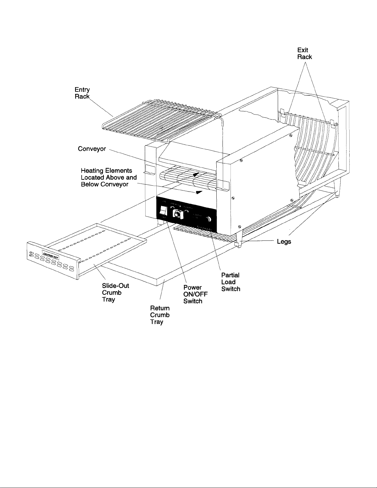
Figure 1
5
Page 6

PARTS IDENTIFICATION AND FUNCTION
ITEM PART NO. DESCRIPTION QTY FUNCTION
1 7610842
TOP PANEL WELDMENT
1
Encloses top of toaster
2 7008168
SIDE PANEL
2
Encloses side componen
ts 3 30051
PANEL, TOP HEATER SUPPORT
1
Attaches to sidewall to support top heater
4 7008170
BOTTOM PANEL
1
Encloses electrical components
5 27470
-
0004
PAN GRILL
1
Protection from fan blades
6
7007044
BELTING
1
Belt which conveys items through toaster
7 3101215
BELT LINKS
3
Links which make up the conveyor belt
8
30067
FRONT ROLLER WELDMENT
1
Front shaft of conveyor
9 7610849
BEARINGS, FRONT ASSEMBLY
2
Bearing and spring assembly
10 7008178
BEARINGS, FRONT
2
Accepts either end of front conveyor shaft
11 3103262
SPRINGS
2
Apply pressure to conveyor
12
30063
REAR ROLLER WELDMENT
1
Rear shaft of conveyor
13 7006963
BEARING, REAR LEFT
1
Accepts left end of rear conveyor shaft
14 7006964
BEARING, REAR RIGHT
1
Accepts right end of rear conveyor shaft
15
7007045
SPROCKETS
2
Engage with both ends of chain to drive conveyor
16 7007605
CHAIN
1
Drives conveyor
17 3101212
MASTER LINK
1
Chain link used to diassemble chain
18 30247
RACK, ELEMENT GUARD
1
Protects elements
19 30050
TOP HEATING ELEMENT ASSEM
BLY 208V
1
Toasts top of item
19
30100
TOP HEATING ELEMENT ASSEMBLY 240V
1
Toasts top of item
20 31582
TOP HEATING ELEMENT 208V
3
Toasting element
20 31583
TOP HEATING ELEMENT 240V
3
Toasting element
21 30340
BUS BAR
3
Connects elements electrically
22 3102634
STRIP, MICA REAR
3
Insulation between heating elements and metal parts
23
2001327
NUT KEPS
6-32 9 Attaches elements
24 7008183
ELEMENT SUPPORT BRACKET
3
Supports and attaches heating elements
25 2000023
SCREW,
6-32 X 1/4,
SLT HEX
4
Attaches
elements
26 7008175
PANEL, TOP HEATER SUPPORT
1
Attaches to sidewall to support top heater
27 30209
BOTTOM HEATER SUPPORT, RIGHT
1
Attaches to right sidewall to support bottom heater
28 30054
BOTTOM HEATER SUPPORT, LEFT
1
Attaches to left sidewall
to support bottom heater
29 31585
BOTTOM HEATING ELEMENT 208V
1
Element toasts bottom of item
29
31587
BOTTOM HEATING ELEMENT 240V
1
Element toasts bottom of item
30 3B20A8801
SCREW WASH HEX HD
8-32 X 3/8" 26 Used to attach parts
31
30519
THERMA
L SNAP DISC
1
Turns toaster off when overheated
32 30697
TRANSFORMER
1
Converts from
208
or 240V to 120V for control circuit
33 3002757
MOTOR
1
Drives the conveyor
34 3002808
SPEED CONTROLLER
1
Controls speed of conveyor
35
30076
SPEED CONTROLL
ER KNOB
1
Turns speed controller to a set speed
36 30069
SPEED CONTROLLER GUARD
1
Knob guard
37 3003828
ON/OFF SWITCH
1
Completes circuit to components
38 27392
-
0002
FAN 1 Cools air in bottom compartment
39
27159
-
0003
CORD SET, COOLING FAN
1
Conn
ects fan with terminal block
40 21226
-
0007
SCREW FAN MOUNTING
4
Used to mount fan
41 3001226
FUSE
1
Shuts off current to motor if current draw is too high
42 30640
PLUG/CORD PIN
&
SLEEVE
-
Used in
U.S.A
.
1
Toaster cord
&
pin plug
42
31974
PLUG/CORD TW
IST LOCK
-
Used in
1
Toaster cord
&
twist lock plug
42 30641
PLUG/CORD PIN
&
SLEEVE
-
1
Toaster cord
&
pin plug
42 31973
PLUG/CORD TWIST LOCK
-
1
Toaster cord
&
twist lock plug
42
30640
PLUG/CORD PIN
&
SLEEVE
-
1
Toaster cord
&
pin plug
43 2001371
NUT, KEPS
10-32 4 Attaches top heater support panel
44 30075
PUSHBUTTON SWITCH w/LIGHT
-
GREEN
1
Momentary switch pushed for partial loads
45 30074
TIME DELAY RELAY
1
Activated by momentary switch to
speed up conveyor
46 30073
SOCKET, OCTAL RELAY
1
Mount for time delay relay
47 30118
RELAY ACCESS DOOR
1
Access for adjusting relay
48 27011
-
0017
TERMINAL BLOCK
1
Connects incoming power
49
7008180
ENTRY RACK
1
Loads items onto conveyor
50 7609868
EXI
T RACK
1
Delivers items to return crumb tray beneath toaster
51
30077
RETURN CRUMB TRAY
1
Receives items from conveyor and catches crumbs
52 7610845
SLIDE IN CRUMB TRAY
1
Catches crumbs from items inside toaster
53
1523B8301
LEGS,
4"
BLACK PLASTIC
4 Adjustable legs used to support the toaster
54
3100558
CAP LEG NON SKID
4
Non skid cap on leg
55 30861
LABEL
1
Caution label
56 321049
LABEL, CAUTION HOT
1
Caution label
57 31616
PANEL REAR
1
Maintains space between toaster and wall
58 30122
INSIDE PANE
L 1 Dissipates heat between toaster and rear panel
59 B301A8855
SCREW
16
Attaches side panel
Not shown
7005957
NAMEPLATE
1
Toastmaster logo
Not shown
3101254
INSULATION CLIPS
4
Used to hold insulation in place
Not shown
30864
WIRE HARNESS
1
Pro
vides connection between electrical components
U.S.A
Non/U.S.A & Germany
Non/U.S.A & Germany
Used in Germany
Not shown
30696 CONVEYOR TOASTER MANUAL
6
1
Toaster operation and maintenance
Page 7

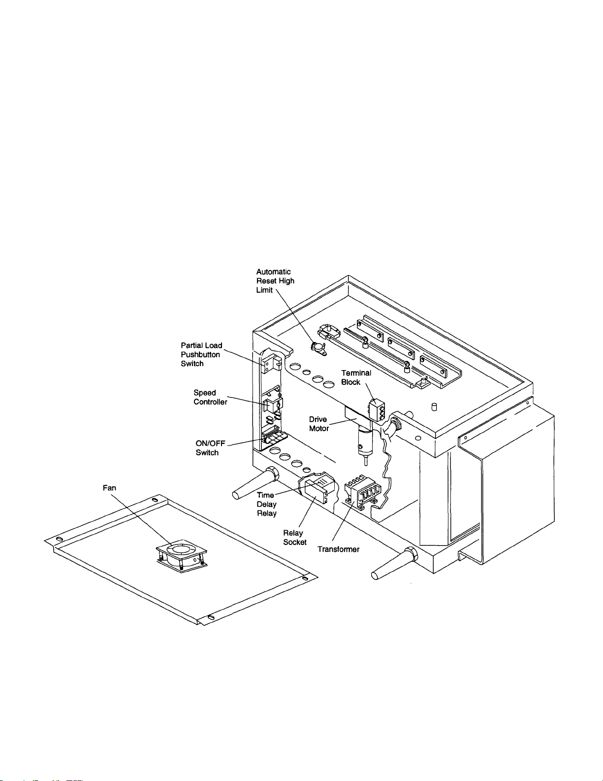
Figure
2
7
7
Page 8

Set-Up:
EQUIPMENT SET-UP AND
CLOSE PROCEDURES
Close:
WARNING: Always disconnect electrical power or
unplug toaster and allow to cool before cleaning
or performing any service.
1. Insert the power cord into a proper 20 Amp.
electrical receptacle.
2. Install the return crumb tray by positioning the
brackets on the side of the tray against the front
legs of the toaster as shown in Figure 4.
3. Install the entry rack, slide-out crumb tray and exit
rack as shown in Figure 4.
4. Turn toaster on by pushing Power ON/OFF Switch
ON.
5. Allow 20 minutes for warm up.
6. Adjust DARKER/LIGHTER Knob to approximately
"5" for toasting a normal batch of 7 to 12 muffin
halves.
7. Loading muffins into toaster:
NOTE: Muffins are placed in toaster cut side up.
Batch Loading-
For batch loading stage muffins on bun spatula
and then place muffins on entry rack with rack in
lowered position. Raise entry rack to feed muffins
onto conveyor.
Continuous Loading-
For partial batch loading stage muffins directly on
entry rack with rack in raised position.
8. Press the PARTIAL LOAD Button for a batch of 6
muffin halves or less and the conveyor will speed
up. It will reset to normal speed automatically
when the partial load has been toasted.
WARNING: Always disconnect electrical power
or unplug toaster before cleaning or
performing any service.
9. Clearing Jams: Use extreme caution when
removing a product jam. It is always better to wait
for toaster to cool, if time permits, before removing
jammed product. Unplug toaster before clearing a
jam. CAUTION: When clearing jams use caution
to not damage elements.
1. With the conveyor running brush any crumbs off the
conveyor and onto the crumb pan below.
2. Turn off the toaster and disconnect electrical power or
unplug toaster. Then allow toaster to cool.
3. Clean the toaster exterior by wiping with a clean,
sanitized towel dampened with a hot solution of McD
All Purpose Concentrate (APC) (HCS) as drawn
from the sink proportioner. Rinse by wiping with a
clean, damp sanitized towel. DO NOT use abrasive
pads of scouring cleansers. They will scratch and dull
the finish.
4. Crumb trays and racks:
WARNING: Hot Surfaces - DO NOT TOUCH HOT
SURFACES OR REACH INTO TOASTER WHEN IT
IS HOT.
After the toaster has cooled, remove the slide-out
crumb tray and the return crumb tray by sliding them
out of the toaster.
CAUTION: Do not remove slide -out crumb tray
while conveyor is moving.
Remove the entry rack and exit rack from toaster.
5. Wash the slide -out crumb tray, return crumb tray and
racks in a hot solution of McD All Purpose Concen-
trate (APC) (HCS). Remove any gold discoloration
from the front of the slide -out crumb tray by
scrubbing with a McD No Scratch Pad.
Rinse well and sanitize by immersing in McD Sink
Sanitizer solution (HCS) (1 pak in 10 gallons of
warm water). Remove parts from sanitizer solution
and allow to air dry.
6. Reassemble all parts onto oven.
CAUTION: DO NOT use excessive water or submerge toaster in water. Electrical problems will
occur.
WARNING: DO NOT stick anything into the
toasting chamber as you may damage the
heating elements and cause electrical shock.
8
Page 9

WARNING
DO NOT OPERATE THE CONVEYOR TOASTER:
Premature failure of the heater elements will occur
and the toaster warranty will be void.
• on either of Its sides
• on its rear surface
• without legs
Figure 4
9
Page 10

TROUBLESHOOTING
PROBLEM
PROBABLE CAUSE
CORRECTIVE ACTION
Muffins must be at room temperature
Product toasted too dark or too light.
Toaster overheats and shuts down.
Toaster will not heat up.
DARKER/LIGHTER control knob
not set correctly.
Partial Load button not being
pressed when 6 or less items are
being toasted.
Using refrigerated or frozen muffins
Time Delay Relay not set correctly.
Cooling fan dirty.
Cooling fan unplugged.
Cooling fan defective. Call service agency.
Thermostat switch overheats and
opens.
Toaster not plugged in. Plug in toaster.
Set knob for correct darkness.
Press Partial Load button when
sliding loads of 6 or less items
onto conveyor.
before toasting. Allow a 2 day old
rotation when using fresh muffins.
Call service agency.
Clean the fan. Follow procedure on
Planned Maintenance Card 1.
Turn ON/OFF switch and main
power switch off, remove bottom
cover and check that plug on fan is
plugged in. Refer to Wiring
diagram.
Call service agency.
Toaster will heat up but
conveyor does not move.
Main power switch turned off. Turn main power switch on.
Defective ON/OFF switch. Replace switch.
Defective receptacle,
power cord or plug.
Thermostat switch is open. Call service agency.
Wire(s) loose. Call service agency.
Foreign object blocking conveyor.
Drive Motor fuse is blown.
Wire(s) loose
Plug into different receptacle.
Replace plug or power cord.
Turn ON/OFF switch and main
power switch off and remove
object from conveyor
Turn toaster off and call service
agency.
Call service agency.
10
Page 11

TROUBLESHOOTING Continued
p
PROBLEM PROBABLE CAUSE CORRECTIVE ACTION
Noticeable burning smell. Toasted item stuck in toaster. Turn ON/OFF switch and main
Too many accumulated crumbs Turn toaster off and let it cool and
in slide-out crumb tray. then remove and clean slide -out
Items feed into machine but are not Exit rack not installed in machine. Install exit rack. Refer to Page5.
delivered to front of return crumb
tray. Item(s) stuck on exit rack. Turn ON/OFF switch off and
ORDERING/SERVICE INFORMATION Ordering
Parts
Service
If technical help is needed contact your local authorized
Use only genuine Toastmaster (manufacturer) replacement parts in your toaster. Use of parts other than those
supplied by manufacturer voids the warranty and U.L.
status.
Your authorized service agency has a parts price list
and will be glad to inform you of the cost of your parts
order.
service agency. Please have the following information
ready when you call:
NOTE: Model # and Serial # are found on the data plate,
refer to Figure 5.
Manufacturer:Toastmaster
Model #: TC208M or TC240M
Locate your desired part in the exploded parts drawing
and then find the item and part number of the part in the
Serial # ________________________
parts list.
List the following ordering information:
Problem with toaster and symptoms: ________
NOTE: Model # and Serial # are found on the data plate,
refer to Figure 5.
Model #:TC208M or TC240M
Manufacturer:Toastmaster
Serial #: _______________
ower switch off and remove
item from toaster.
crumb tray. Refer to Page 10.
remove item(s).
Item No(from parts list): _______________
Part No (from parts list): _______________
Return Policy
An RGA number (Return Goods Authorization) must be
obtained from Toastmaster before returning a product.
Description: _______________
Shipping charges must be prepaid by buyer. Returned
goods are subject to Toastmasters inspection and accep-
Order the required parts from your local authorized ser-
tance.
vice agency.
Delivery Date of Toaster: _______________
Local Service Agency:
Name _______________________
Number & Street _________________
City, State, Zip ___________________
Phone Number___________________
Page 12

NON-SCHEDULED MAINTENANCE
This section provides information for replacement of various parts and components as necessary. Before replacement
of any parts refer to the Troubleshooting Section for assistance in determining the cause of the problem and to verify
that replacement is required. If necessary contact your local authorized service agency for assistance.
CAUTION: Before performing any maintenance:
1. Turn toaster ON/OFF switch OFF.
2. Turn main power switch off.
3. Unplug toaster from receptacle.
4. Allow toaster to cool.
Tools Necessary: Flat blade screwdriver, Philips screwdriver, Set of Alien wrenches, Needle nose pliers, Regular
pliers, Set of sockets with handle
A. Top Heating Elements Replacement
1. Remove the toaster right side cover by removing the 6 screws.
2. Remove the 6 nuts from the right side top heater support panel.
3. Slide the heater assembly part way out and then disconnect the 2 wires from the heater terminals by removing
the 2 screws and nuts. Refer to Figure 6.
4. Remove the heat er assembly from the toaster and then remove the bus bar(s) and the mica strip from the
heater to be replaced. Refer to Figure 7.
5. Remove the 2 screws attaching the heater to the heater supports.
6. Replace the heater with the new one and reassemble part s in the reverse order they were removed. Be sure to
connect wires to heater terminals before sliding heater assembly all the way into toaster. Refer to Figure 7 to
be sure heater assembly and element guard are mounted on studs and inserted into holes.
12
Page 13

Figure 7
13
Page 14

B. Bottom Heating Elements Replacement
1. Remove the toaster right side cover by removing the 6 screws.
2. Loosen 4 motor mounting screws and move motor/shaft to the right and then remove the drive chain from the
motor sprocket.
3. Remove the 6 nuts from the right side bottom heater support panel and the 2 screws to remove the wires from
the heater terminals. Refer to Figure 8.
WARNING: Be careful not to bend or damage the heater terminals.
4. Remove heater assembly from toaster. It may be necessary to use a screwdriver to pry slightly at each end of
heater support bracket. Do not damage or bend the heater support panel.
5. Replace bottom heater element by removing 2 screws attaching it to heater support panel and attaching new
heater element.
6. Reassemble parts in the reverse order they were removed. Be sure to insert heater element into the 2 bracket
openings on the left side of toaster when sliding the heating element into the toaster. Refer to Figure 8. Also
position heater support against spring at end of shaft bearing when reassembling heater assembly into toaster.
7. Reassemble drive chain onto motor sprocket and then push the motor to the left to place tension on the chain.
The drive chain must be tight. Tighten the 4 motor mounting screws.
8. Connect wires to new heating element.
Figure 8
14
Page 15

C. Conveyor Belt Replacement:
1. Remove the right and left side covers by removing the 6 screws on each side. On right side of toaster use a
screwdriver to push the bearing as shown. With the hole in the bearing lined up with the slot in the retaining
plate, push the conveyor shaft thru the slot. See Figure 9.
2. To remove all tension on the conveyor belt push the conveyor shaft as far as possible toward the right side
until the left end of convey or shaft is free of the left side bearing. See Figure 9.
3. Turn the conveyor belt so the master links are at the front of the toaster. See Figure 9.
4. Using long nose pliers remove the three master links. Replace the belt or replace the damaged links in the belt.
5. Reassemble the master links into the conveyor belt.
6. Push the left side bearing with a screwdriver as shown in Figure 9 and reinsert the shaft into the bearing.
Release the shaft from the right side support slot and center the shaft between the side walls.
Figure 9
15
Page 16
D. Electrical Components Replacement (Drive Motor, Transformer, Fan, On/Off Switch, Speed Controller,
Pushbutton Partial Load Switch)
1. Lift the toaster onto its side as shown.
2. Remove the bottom panel by removing the 4 screws.
3. The electrical components are now accessible. Remove wires one at a time from the old component and
replace them on the new component. Remove the screws and/or nuts attaching the old component to the
toaster and remove it. Mount the new component onto the toaster.
4. Use the wiring diagram to help connect the wires to the new component if necessary.
5. Replace bottom panel using the 4 screws that were removed.
Figure 10
Page 17

E. Time Delay Relay Replacement
1. Remove the door in the left side cover by removing 1 screw.
2. The time delay relay is now accessible. Remove the relay from its socket and replace with the new relay.
3. Replace the door in the left side cover.
F. Relay Socket Replacement
1. Remove the toaster left side cover by removing the 6 screws.
2. Remove the Time Delay Relay from the socket.
3. Remove wires one at a time from the old relay socket and replace them on the new relay socket. Remove the
screws attaching the old relay socket to the toaster and remove it. Mount the new relay socket onto the
toaster.
4. Use the wiring diagram to help connect the wires to the new relay socket if necessary.
5. Replace side cove r using the 6 screws that were removed.
6. Refer to MRC #19 for instructions to properly adjust time delay relay.
G. Automatic Reset High Limit Replacement
1. Remove the right side cover by removing 6 screws.
2. The Automatic Reset High Limit is now accessible. Remove wires one at a time from the old High Limit and
replace them on the new one. Remove the screws attaching the old High Limit to the toaster and remove it.
Mount the new High Limit onto the toaster.
3. Use the wiring diagram to help connect the wires to the new High Limit if necessary.
4. Replace side cover using the 6 screws that were removed.
17
Page 18
SCHEMATIC
Figure 11
18
Page 19

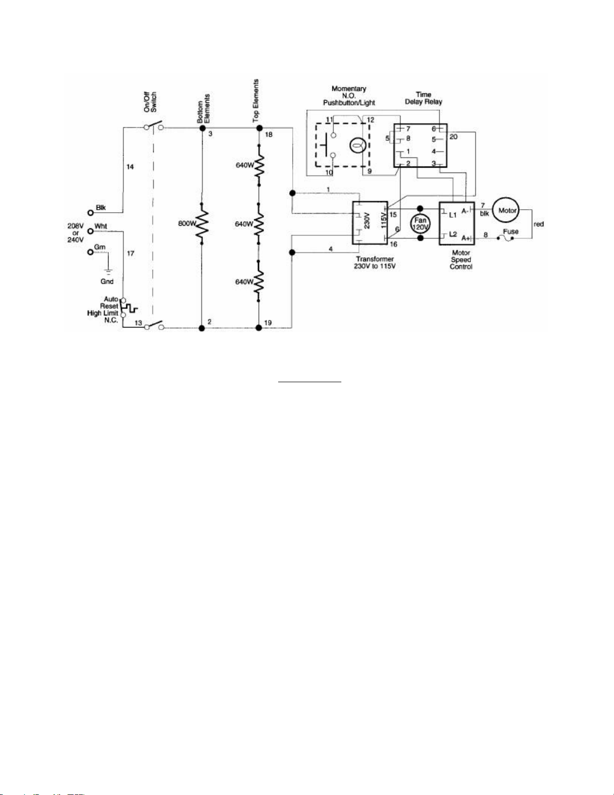
WIRING DIAGRAM
Figure 12
19
 Loading...