

TOA-DKK TB-31 Instruction Manual
HAND HELD TURBIDITY METER
MODEL TB-31
No. TB3-LB16000E
Please keep this instruction manual close at hand of the persons who are in charge of
the operation of this product.
Before operating this product, please read this instruction manual carefully for its
correct handling.

Model: TB-31 Introduction
Introduction
(a) Thank you for your purchase of the Model TB-31 Hand Held turbidity meter (hereinafter called the
instrument or the product). The instrument has a waterproof construction suitable for on-site
measurements and a clock function and data memory function indispensable in data management.
In addition, consumed power is lowered up to 1/7 compared with the conventional products.
(b) An AC adapter, external printer, and RS-232C connection cable can be connected to the instrument
main body as optional devices. The data of measured value and calibration value can be printed by
the printing function of an external printer.
(c) Since important items are described in “Safety Information”, read the contents carefully. After
reading this manual, store it in a convenient place.
-
1 -
Model: TB-31 Safety Information
Safety Information
(1) Meaning of markings
The signal terminology and symbols related to warnings in the instruction manual are defined below.
The alert symbol mark (
also means “Refer to the instruction manual.”
:
Indicates the degree of hazard which can lead to death or serious injury if you fail to operate the
product properly.
Serious injury means an injury such as loss of sight, burns (high temperature or low temperature),
electric shock, bone fracture and poisoning, and the aftereffects of the injury remains or the injury
requires hospitalization or long periods of outpatient treatment.
:
Indicates the degree of hazard/loss which can result in injury or property damage if you fail to operate
the product properly.
Injury means an injury not requiring hospitalization or long periods of outpatient treatment and refers
to burns or electric shock. Property damage refers to widespread damage to the home, household
goods and livestock, pets, equipment, materials, etc. (damage to other than the product itself).
: General caution mark) indicates the possibility of hazard or damage and
【IMPORTANT】
〔NOTE〕
①, ②, ③ Indicates item numbers such as the ones used in operations.
Indicates important matters other than
matters such as preventing damage to the product main body, preventing data
destruction, preventing wasting time, maintaining performance, and observing
regulations.
Indicates comments, reasons, background information, a case example and other
items to help the reader understand the meaning.
Indicates reference items.
(2) Safety compliance items
Explosion, fire, electric shock, and battery leakage
Do not use the product in an area where explosive gas or flammable gas exists.
Do not place the product in a fire or burn it. Doing so may cause an explosion or fire
inside the product.
Always verify that the power is off before connecting or disconnecting the plug, AC
adapter cover, or input/output cover. Water or reagent entering the product may short
the circuits and cause electric shock or fire.
When the product will not be used for a long time, always remove the AA size alkali
battery or AA size rechargeable nickel hydride battery.
Liquid may leak from the battery.
and . They are the
-
2 -

Model: TB-31 Safety Information
Tumbling
When working at the measurement point, prevent the tumbling using such as a safety
belt, etc. In addition, to prevent injury, wear a helmet, life jacket, safety boots, etc.
Waterproofing
The construction of the product becomes waterproof (IP67) only when the sensor,
battery cover, AC adapter cover, and input/output cover are installed properly.
Do not touch the instrument with wet hands or wash it with water when the sensor
has been removed or the battery cover, AC adapter cover, or input/output cover is
opened. Besides, do not install or store the product where water or reagent may
enter it.
Mixing in
Do not drop the instrument body into the measurement tank. Doing so may cause
trouble.
Disassembly and Modification
Do not disassemble or modify the sections of the product that are not described in
the instruction manual. The product can be damaged.
Caution Label Lost
If any caution label affixed to this product becomes too difficult to read or lost, please
order a new one through your local sales agent or our sales office and affix it to its
original position.
(3) Notes on use of the instruction manual
Important items such as “Safety compliance items” are described in this manual. Handle the manual
as follows:
(a) The instruction manual is required not only at the start of operation but also required when
maintenance is performed or in case a failure occurs. Please keep the manual at hand all the time so
that the operator who actually operates the product can read the manual at any time.
(b) If the manual is lost or too smeared to read, please order a new copy through your local sales agent
or directly from our sales office.
(c) Some of the diagrams used in the manual or on product labels may be modified with part of their
shapes or displays omitted or they may be described in abstract form. In addition, numbers etc.
shown on the screen example are just examples for such cases.
(d) The contents of the manual may be changed without prior notice for reasons such as to improve
performance.
(e) Intellectual property right of the manual belongs to DKK-TOA. All or part of the manual must not
be reproduced without permission.
-
3 -

Model: TB-31 Warranty
Warranty
(1) Warranty Coverage
DKK-TOA Corporation (DKK-TOA) warrants its products against defective material or workmanship for the warranty
period.
(a) The warranty period is two years from the date of delivery to the original user.
(b) Specific written agreements with DKK-TOA, if any, shall take precedence over this warranty.
(c) The limitation of warranty described herein may not apply where applicable laws do not allow such limitation.
(2) Limited Warranty
This warranty does not cover the cases listed below.
(a) Direct or indirect failure or damage caused by the use of the product for a purpose or in a manner not prescribed by
the specifications or the instruction manual for the product.
(b) Direct or indirect failure or damage caused by force majeure, including but not limited to an act of God, natural
disaster such as earthquake, storm and flood damage, and lightning, fire, accident, abnormal voltage, salt damage,
gas damage, labor unrest, acts of war (declared or undeclared), terrorism, .civil strife, or acts of any governmental
jurisdiction.
(c) Failure or damage caused by any repair or modification not authorized by DKK-TOA.
(d) Failure or damage caused by the transport, moving, or dropping of the product after the purchase that is not
attributable to DKK-TOA.
(e) Electrodes, sensors, and consumables (The warranty period for each part has priority when the period is shorter
than that for the main unit of the product. If the customer requires any part after more than six months from the
date of manufacture, consult DKK-TOA or its distributor.)
( f ) Failure or damage caused by the use of consumables, parts, or software not supplied by DKK-TOA.
(g) Malfunctions or damage caused by the use of connecting equipment not supplied by DKK-TOA.
(h) Loss of data, settings, programs, or software stored on the product not attributable to DKK-TOA.
( i ) Any product other than DKK-TOA’s, if specified by the purchaser or user, that incorporates, or is incorporated into
or combined with DKK-TOA’s products (*1). In such cases, this warranty covers DKK-TOA’s products only.
( j ) Any product not under proper maintenance in accordance with the instruction manual furnished by DKK-TOA.
(k) Products without a nameplate (excluding products proved to have been delivered by DKK-TOA).
EXCEPT AS EXPRESSLY SET FORTH IN THE PRECEDING SENTENCES, DKK-TOA MAKES NO
WARRANTY OF ANY KIND WHATSOEVER WITH RESPECT TO ANY PRODUCT. DKK-TOA EXPRESSLY
DISCLAIMS ANY WARANTY IMPLIED BY LAW, INCLUDING BUT NOT LIMITED TO ANY WARRANTY OF
MERCHANTABILITY OR FITNESS FOR A PARTICULAR PURPOSE.
LIMITATION OF REMEDIES: In the event that a defect is discovered within the warranty period, DKK-TOA or its
authorized distributor will, at its option, repair or replace the defective product or its part, or will refund the purchase
price of the product. THIS IS THE EXCLUSIVE REMEDY FOR ANY BREACH OF WARRANTY.
LIMITATION OF DAMAGES: IN NO EVENT SHALL DKK-TOA BE LIABLE FOR ANY INCIDENTAL OR
CONSEQUENTIAL DAMAGES OF ANY KIND FOR BREACH OF ANY WARRANTY, NEGLIGENCE, ON THE
BASIS OF STRICT LIABILITY, OR OTHERWISE.
(3) Others
(a) Product parts for maintenance (*2) will normally be supplied for five years (*3) from the date manufacturing and
sales are discontinued.
(b) The cause of any malfunction or damage shall be determined by a DKK-TOA technician.
(c) For repairs, contact a local distributor in your country or state.
*1: Warranties for products from other companies must be maintained by the user.
*2: Maintenance parts refers to parts that are required to maintain operation of the product.
*3: This five-year period is subject to availability of parts or their replacement.
P30 <1>
-
4 -
Model: TB-31 Reading Guide
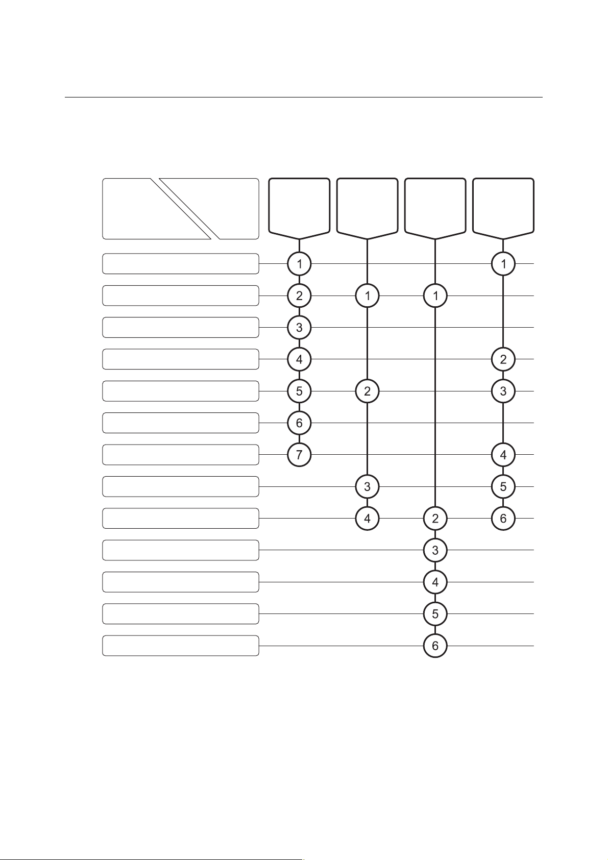
Reading Guide
Refer to the necessary sections of this instruction manual depending on your purposes such as
understanding the outline of this product or starting the product as shown below. The numbers in
circles indicate sections to be referred to in sequential order.
Section
●Introduction
●Safety Information
1. Content of package
2. Specifications and Functions
3. Name and Function of Each Part
4. Preparations
5. Basic Operation
Purpose
Start (start-up) Understand the
Perform
respective
operations
Maintenance
and inspection,
and
troubleshooting
outline of this
product
6. How to Use Various Functions
7. Functions by Optional Devices
Connection
8. Maintenance and Inspection
9. Troubleshooting
10. Transport, Storage, and Disposal
11. Parts/Options List
-
5 -

Model: TB-31 Table of Contents
Table of Contents
●Introduction
●Safety Information
(1) Meaning of markings ⋅⋅⋅⋅ 2
(2) Safety compliance items ⋅⋅⋅⋅ 2
(3) Notes on use of the instruction manual ⋅⋅⋅⋅ 3
●Warranty
●Reading Guide
1. Content of Package ··················································· 9
··········································································································· 1
··························································································· 2
·················································································································· 4
··································································································· 5
2. Specifications and Functions ···································· 10
(1) Specifications ⋅⋅⋅⋅ 10
(2) Functions ⋅⋅⋅⋅ 11
3. Name and Function of Each Part ······························ 12
(1) Main body and operation panel ⋅⋅⋅⋅ 12
(2) Display ⋅⋅⋅⋅ 13
(3) Turbidity sensor (Model ELL-011) ⋅⋅⋅⋅ 15
4. Preparations ····························································· 16
4.1 Loading the Batteries ······················································································ 16
4.2 Installing and Removing the Protective Cover ·················································
(1) Installing the protective cover ⋅⋅⋅⋅ 19
(2) Removing the protective cover ⋅⋅⋅⋅ 19
4.3 Turbidity Sensor Connection ··········································································· 21
4.4 Turbidity Sensor Preparation ···········································································
19
23
5. Basic Operation ························································ 24
5.1 Operation Screens Map··················································································· 24
5.2 Turning on the Power ······················································································ 25
5.3 Time Setting ···································································································· 26
5.4 Calibration Data Display and Deletion ····························································· 27
(1) When deleting the calibration data ⋅⋅⋅⋅ 27
(2) Calibration data display ⋅⋅⋅⋅ 27
(3) Calibration data deletion ⋅⋅⋅⋅ 28
-
6 -

Model: TB-31 Table of Contents
5.5 Performing the Calibration ··············································································· 29
(1) One-touch zero calibration ⋅⋅⋅⋅ 29
(2) Span calibration ⋅⋅⋅⋅ 30
5.6 Measurement ·································································································· 34
(1) Measurement by real-time mode ⋅⋅⋅⋅ 35
(2) Measurement by batch mode ⋅⋅⋅⋅ 37
5.7 Ending Measurement ······················································································ 39
6. How to Use Various Functions ·································· 40
6.1 Auto Hold Function ··························································································
(1) Memory execution by auto hold ⋅⋅⋅⋅ 40
6.2 Data Memory Function ···················································································· 42
(1) Data number setting ⋅⋅⋅⋅ 42
(2) Memory execution by manual key ⋅⋅⋅⋅ 43
(3) Memory data recall and erasing ⋅⋅⋅⋅ 44
6.3 Interval Function ····························································································· 45
(1) Interval function and time settings ⋅⋅⋅⋅ 45
(2) Memory execution by interval ⋅⋅⋅⋅ 47
6.4 Display Range Switching Setting ····································································· 49
6.5 Measurement Unit Setting ··············································································· 50
6.6 Response Setting ···························································································· 51
6.7 Temperature Calibration Function ··································································· 52
6.8 Memory Overwrite On/Off Setting ···································································· 54
6.9 Buzzer On/Off Setting ·····················································································
6.10 Auto Power Off Setting ···················································································· 56
40
55
7. Functions by Optional Devices Connection ··············· 57
7.1 Connection of Optional Devices ······································································ 57
(1) Connection of AC adapter ⋅⋅⋅⋅ 57
(2) Connection of analog output cable ⋅⋅⋅⋅ 58
(3) Connection of external printer connection cable ⋅⋅⋅⋅ 59
(4) Connection of RS-232C connection cable ⋅⋅⋅⋅ 59
7.2 Printing Function by External Printer ······························································· 61
(1) Printing of calibrated value ⋅⋅⋅⋅ 61
(2) Printing of measured value ⋅⋅⋅⋅ 62
7.3 RS-232C Communication Function ································································· 65
(1) RS-232C communication format ⋅⋅⋅⋅ 65
(2) Data collection software ⋅⋅⋅⋅ 70
-
7 -

Model: TB-31 Table of Contents
7.4 Connection of Recorder ···················································································
(1) Connection of analog output cable ⋅⋅⋅⋅ 71
(2) Analog output specifications ⋅⋅⋅⋅ 72
(3) Analog output cable terminals wiring ⋅⋅⋅⋅ 72
8. Maintenance and Inspection ····································· 73
8.1 Instrument Body Maintenance ········································································· 73
8.2 Turbidity Sensor Maintenance ········································································· 74
(1) Daily maintenance ⋅⋅⋅⋅ 74
(2) When not recovered even by daily maintenance ⋅⋅⋅⋅ 75
8.3 Battery Replacement Period ············································································
9. Troubleshooting ························································ 77
9.1 Safety Precautions When an Abnormality Occurred ········································ 77
9.2 Error Display ··································································································· 78
9.3 Other Troubles and Countermeasures ····························································· 79
9.4 How to Reset the System ················································································ 81
71
76
(1) Returning all data and parameters to their factory setting ⋅⋅⋅⋅ 81
(2) Returning data other than the clock data and measured data to their
factory setting ⋅⋅⋅⋅ 81
10. Transport, Storage, and Disposal ······························ 82
10.1 Transport ········································································································· 82
10.2 Storage ············································································································ 83
10.3 Disposal ·········································································································· 83
11. Parts/Options List ····················································· 84
(Last page ⋅⋅⋅⋅ 86)
-
8 -
Model: TB-31 1. Content of Package
1. Content of Package
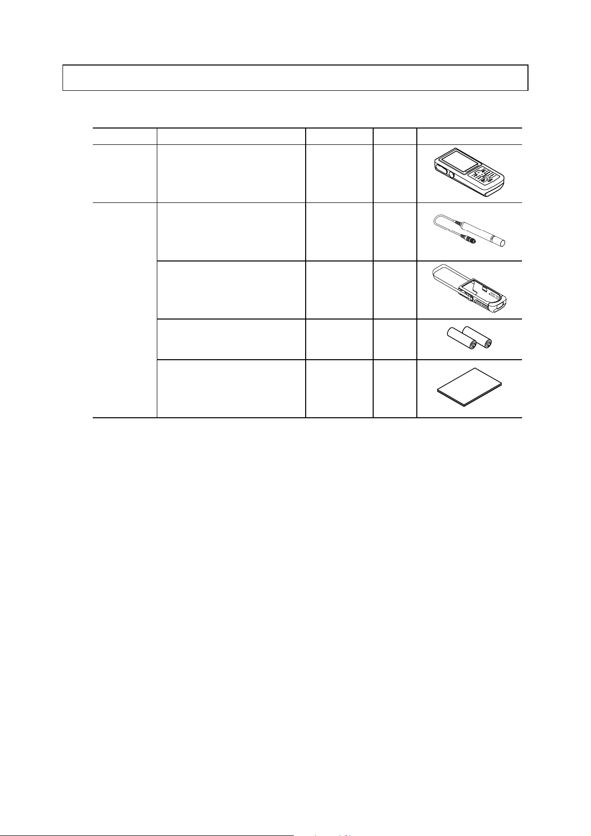
Content of Package List
Classification Description Model Quantity Appearance
Main body Hand held turbidity meter TB-31 1
Accessories Turbidity sensor (Standard: Cable
length 2m) (with built-in memory)
*1
ELL-011 1
Protective cover (with shoulder
belt)
AA size dry battery *2
(sample supply)
Instruction manual
7258070K 1
−
−
2
1
〔NOTE〕 *1: This accessory is not supplied if only main body is ordered.
*2: Attached dry batteries are supplied as sample. Since the battery life may be extremely
short, replace it with an AA size alkali dry cell battery or AA size rechargeable Nickel
hydride battery available on the open market.
-
9 -

Model: TB-31 2. Specifications and Functions
2. Specifications and Functions
(1) Specifications
Product name Hand held turbidity meter
Model TB-31
Measuring method Near infrared 90 degree scattering light measurement
Measuring object Turbidity, temperature
Display Digital
Simultaneous display of turbidity, temperature, and time (month and day,
hour and minute)
Turbidity Range 0.0 to 80.0NTU(mg/L), 0 to 800NTU(mg/L)*1
Resolution 0.1NTU(0.0 to 80.0NTU(mg/L)), 1 NTU(0 to 800NTU(mg/L))
Temperature Range 0.0 to 50.0ºC (However, test water shall not be frozen.)
range
Measuring
Turbidity Range 0.0 to 88.0NTU(mg/L), 0 to 880NTU(mg/L)
Temperature Range −5.0 to 110.0ºC
range
Display
Turbidity Within ±0.5NTU (0.0 to 80.0)
ty
Temperature Within ±0.5ºC
Repeatabili
Resolution 0.1ºC
Resolution 0.1NTU(0.0 to 80.0NTU(mg/L)), 1 NTU(0 to 800NTU(mg/L))
Resolution 0.1ºC
Within ±5NTU (0 to 800)
At fixed conditions
At fixed conditions
Calibration Zero, Span calibration
Water depth Within 50m (0.5MPa or equivalent)
Water Proof IP67 *2
Printing function *3 Interface is standard equipment, printer is optional
RS-232C interface
(Communication conditions
fixed) *3
Analog output Turbidity value, temperature value, range value
Power supply AA size alkali dry cell battery (2), AA size rechargeable nickel hydride
Main body dimensions Approx. 35 (Height) × 68 (Width) × 173 (Depth) mm
Main body weight Approx. 280g
Performance guarantee
temperature range
*1: NTU indicates turbidity calibrated using a formazin standard solution and mg/L indicates turbidity
calibrated using a kaolin standard solution.
*2: Invalid when no sensor is connected or external input/output (optional) is used.
*3: Cannot be used simultaneously
*4: 0 to 40
o
C when optional AC adapter and external printer used.
External input and output (Uninsulated)
battery (2) or AC adapter (optional) *3
0 to 45ºC *4
However, for turbidity sensor, temperature shall not be changed rapidly.
-
10 -

Model: TB-31 2. Specifications and Functions
〔NOTE〕 • This sensor is not for continuous measurements. When you want to perform simple
monitoring, make the maximum continuous usage time approximately 24 hours.
• To maintain measurement accuracy, careful cleaning is necessary.
(2) Functions
Clock function Built-in
Data storage 1000 data (measured date & time, turbidity value, temperature)
Interval time function [OFF / S interval / L interval]
Data memory*1 of
Short interval: 00 mins 01 secs to 99 mins 59 secs
Long interval: 00 hours 02 mins to 99 hours 59 mins
Auto power off On/Off setting is possible.
ON: Power is turned off when key operation is not performed for 10 mins/20
mins/30 mins/60 mins.
Temperature calibration
function
Auto hold function Provided
Printing function When external printer is connected:
RS-232C interface Standard equipped (Interactive) (Uninsulated)
Analog output Standard equipped (Uninsulated)
1 point calibration
1. Printing of measured value
• Manual printing
• Printing using interval time function
• Printing of stored data
• Printing using auto hold function
• Printing of calibration data
*1 When an external printer is connected, the minimum interval becomes 5 seconds.
-
11 -
Model: TB-31 3. Name and Function of Each Part
3. Name and Function of Each Part
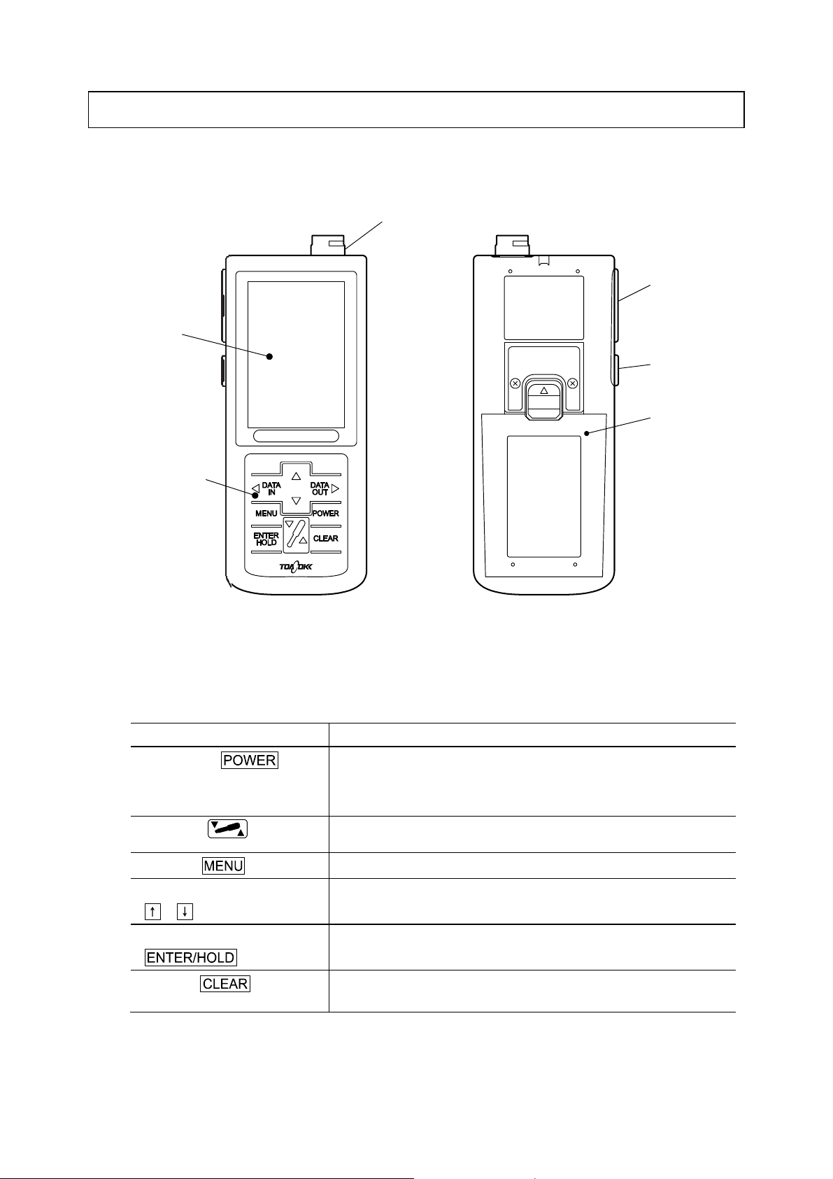
(1) Main body and operation panel
Sensor jack
Input/output cover
Display
AC adapter
cover
Battery cover
Operation
panel
Names of Main Body
Types and Functions of Operation Panel Keys
Type of key ( Notation in text) Function
Power switch ( )
Sensor key ( )
Menu key ( )
Up key, down key
( , )
Enter/hold key
( )
Clear key ( )
• When pressed for 2 seconds or more, the power is turned on and off
(ON/OFF).
• When pressed for less than 2 seconds, the display returns directly to
the Measurement standby screen from any other screen.
• When pressed for 2 seconds or more, one-touch zero calibration is
executed.
• Switches to the Menu screen.
• Change values (increase/decrease) and switch selectable functions.
• Enters values and executes the auto hold function.
• Switches to the next screen.
• Clears the calibration value, etc.
• Returns to the previous screen.
-
12 -
(To be continued)
Model: TB-31 3. Name and Function of Each Part
(Continued from previous page)
Type of key ( Notation in text) Function
Data in/left arrow key
( )
Data out/right arrow key
( )
• Saves the measured value.
• Selects the MODE, No., INT., CLOCK, C., or etc. mark at the Menu
screen.
• Displays the saved measured value.
• Selects the MODE, No., INT., CLOCK, C., or etc. mark at the Menu
screen.
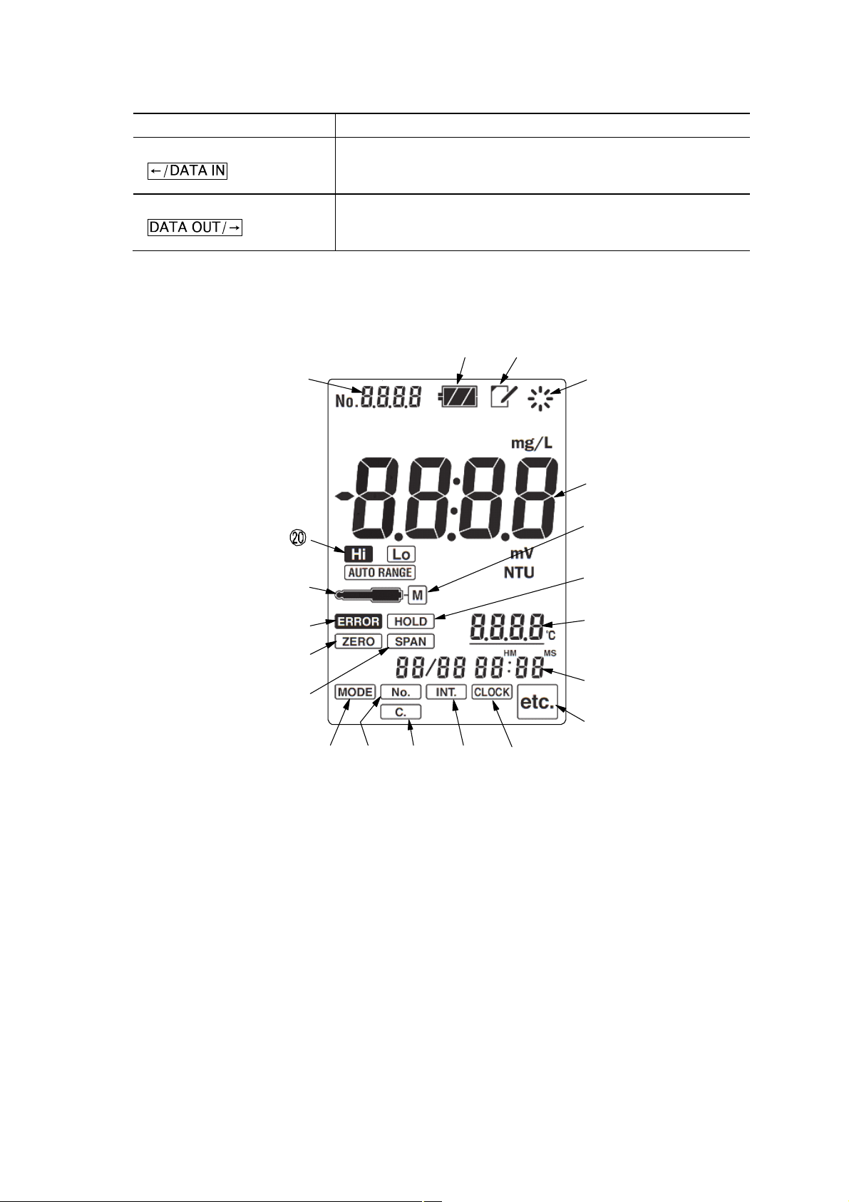
(2) Display
②
①
⑥
⑧
⑩
⑪
⑭⑮ ⑯ ⑰ ⑱
Display
③
④
⑤
⑦
⑨
⑫
⑬
⑲
-
13 -
Model: TB-31 3. Name and Function of Each Part
Names and Functions of Display
No.
① Data number display • Displays the data number.
② Battery mark
( )
③ Memory mark
( )
④ Operation display mark
(
⑤ Main display • Displays the turbidity value.
⑥ Sensor mark
( )
⑦ M mark
(M)
⑧ Error mark
(
⑨ Hold mark
(
⑩ Zero mark
(
⑪ Span mark
( )
⑫ Temperature display • Displays the temperature measured value.
⑬ Date/time display • Displays the current date/time (Month/day Hour : minute)
⑭ MODE mark
(
⑮ No. mark
(
⑯ C. mark
(
⑰ INT. mark
(
⑱ CLOCK mark
(
⑲ etc. mark
(
⑳ Range mark
(
Names
(Notation in text)
s
)
ERROR
HOLD
MODE
No.
INT.
CLOCK
etc.
)
)
)
)
)
)
)
)
)
)
Functions
• Displays the remaining battery capacity (4-step display).
• Lights when memory data is displayed.
• Displays the operation state.
• Lights when an sensor is connected.
• Lights when the body is combined with a “Cal-memo” sensor.
• Blinks when an error occurs.
• Lights when the measured value is being held (hold standby state).
• Blinks during auto hold execution.
• Lights steadily after one-touch zero calibration execution.
• Blinks at one-touch zero calibration execution.
• Lights steadily after span calibration execution.
• Blinks at span calibration execution.
• After temperature calibration execution, displays an underline.
• Lights when the batch mode and real-time mode are switched.
• Lights when the data number is set.
• Lights when the calibration value is confirmed or set.
• Lights when the interval function/time is set or the interval is
executed.
• Blinks in the interval standby state.
• Lights when clock adjustment is set.
• Lights at each setting such as auto power off reset.
• Displays the range. (Hi / Lo / AUTO RANGE)
(Hi: 0 to 800, Lo: 0.0 to 80.0, AUTO RANGE: Auto range)
-
14 -
Model: TB-31 3. Name and Function of Each Part
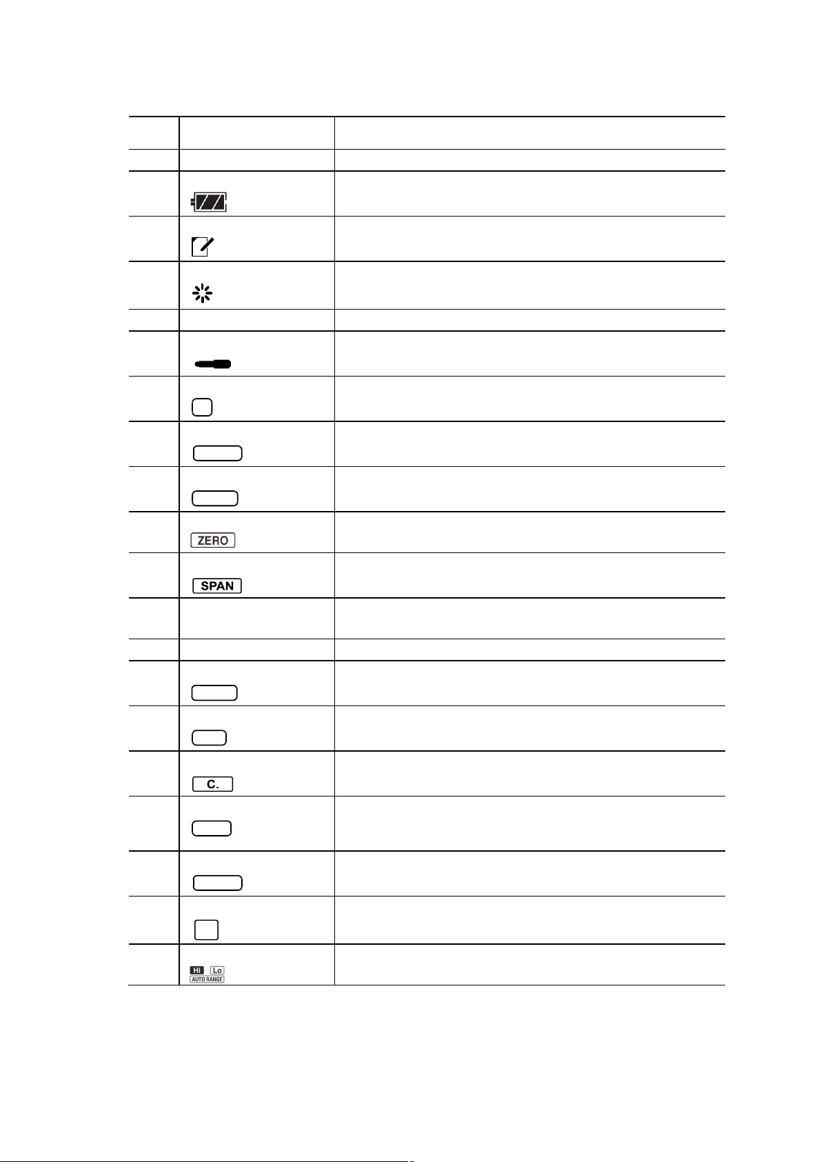
(3) Turbidity sensor (Model ELL-011)
②
③
④
⑤
⑥
⑦
Turbidity Sensor (Model ELL-011)
①
⑧
Names and Contents of Turbidity Sensor (Model ELL-011)
No. Names Contents
① Plug • Plug for connecting the sensor to the instrument body.
② Body
③ Air vent groove
④ Light-emitting part
⑤ Light-receiving part
⑥ Temperature sensor
⑦ Protective tube • Installed to the body at measurement.
⑧ Cable fixing bracket • Bracket for fixing the cable to the instrument body.
-
-
-
-
-
-
15 -
Model: TB-31 4.1 Loading the Batteries
4. Preparations
4.1 Loading the Batteries
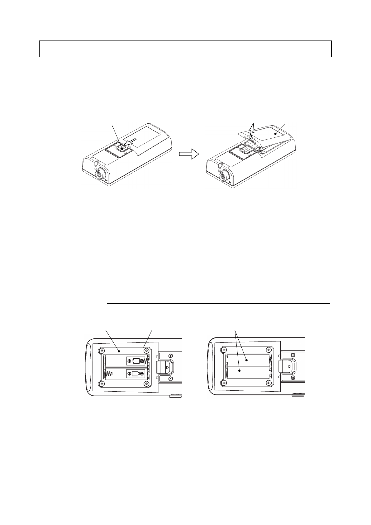
① Remove the battery cover. ⋅⋅⋅⋅⋅⋅ After sliding the battery cover holder in the arrow direction
with your finger, remove the battery cover while pulling both ends of the battery cover with your
fingers.
Battery cover holder
Removing the Battery cover
② Load the batteries. ⋅⋅⋅⋅⋅⋅ After checking the battery loading direction of the battery compartment,
load AA size alkali dry cell batteries (2 pieces) or AA size rechargeable nickel hydride batteries (2
pieces).
•When alkali dry cell batteries are used, the battery drive time is about 120 hours for the
continuous measurement and about 7000 times for the batch measurement. (The drive time may
be different depending on the battery capacity, usage environment, etc.)
• See 8.3 “Battery replacement period” for the battery replacement period.
【IMPORTANT】 • When loading the batteries, be sure that the “+” and “–” polarities are
correct.
Battery cover
Battery compartment
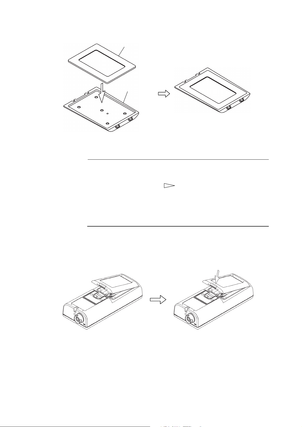
③ Check the packing. ⋅⋅⋅⋅⋅⋅ Verify that the packing is properly installed to the battery cover
(inside).
Rib
Loading the Batteries
-
16 -
Batteries (2 pieces)
Model: TB-31 4.1 Loading the Batteries
Packing
Battery cover (inside)
<State with packing installed properly>
<When replacing>
Checking the Packing
【IMPORTANT】 • When installing the battery cover, confirm that the packing and the rib
(part which seals the packing) are not scratched, deteriorated or dusty.
• If the packing is scratched, cracked, or otherwise deteriorated, always
replace it with new packing. (
the packing and rib are dusty, clean up them. In each case, the
waterproofing function cannot be guaranteed if used as is.
• When replacing the packing, refer to the figure shown above and confirm
that the packing is installed properly. If the packing is separated from the
battery cover, re-install it properly.
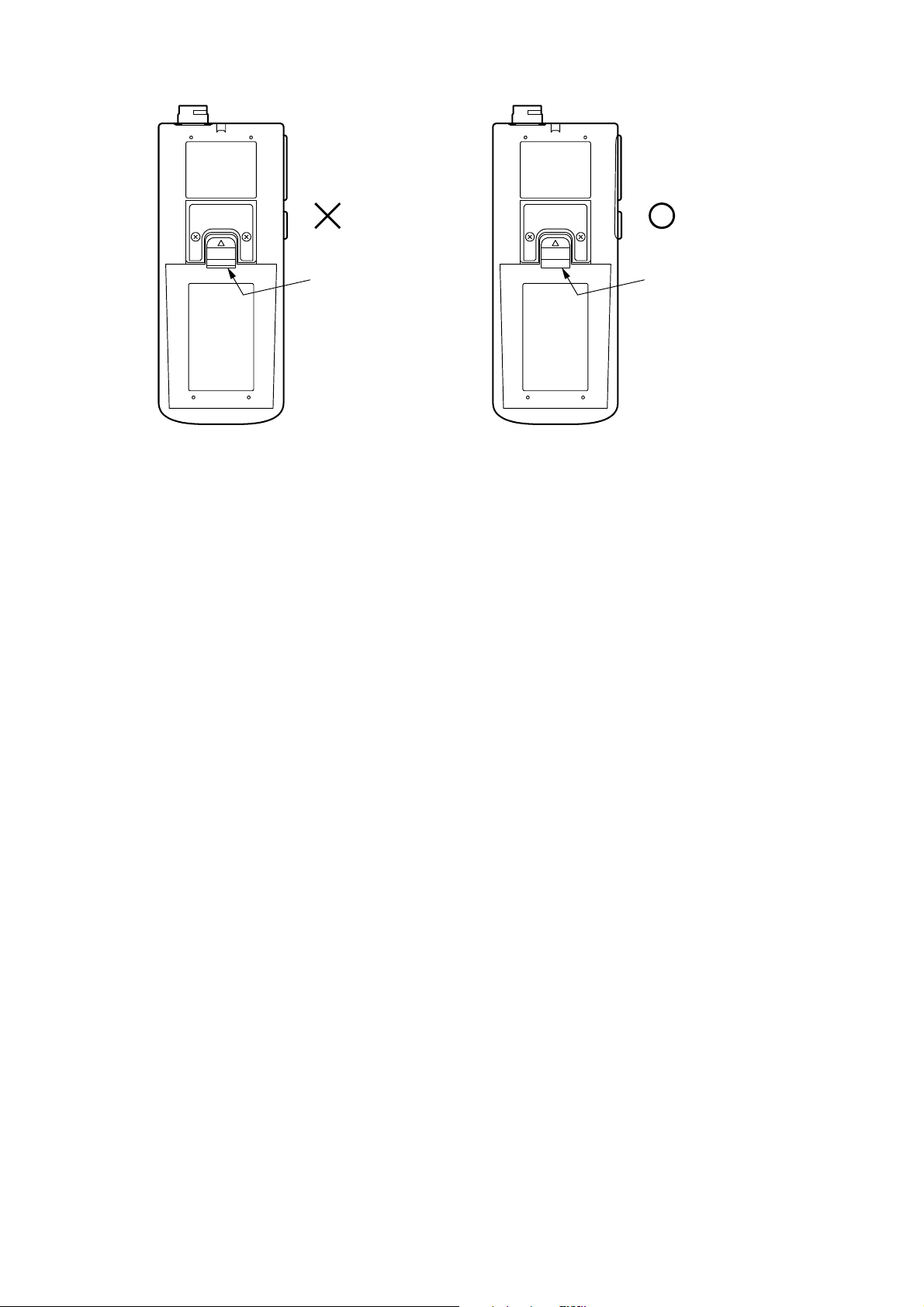
④ Install the battery cover. ⋅⋅⋅⋅⋅⋅ Hook the tab of the battery cover to the body and install the cover
to the body by pushing it in the arrow direction. At this time, confirm that the end of the battery
cover holder is firmly inserted into the notch of the battery cover. If it is not firmly inserted, push
the battery cover against the instrument body.
11. “Parts/Options List”) In addition, if
Hooking the Battery Cover Tab Installing the Battery Cover
-
17 -
Model: TB-31 4.1 Loading the Batteries
End of battery cover
holder is not firmly
inserted into the notch
of the battery cover.
Checking the end of the Battery Cover Holder
End of battery cover
holder is firmly inserted
into the notch of the
battery cover.
-
18 -
Model: TB-31 4.2 Installing and Removing the Protective Cover
4.2 Installing and Removing the Protective Cover
Injury
Handle the instrument body carefully so as not to damage it. If the body is damaged
by mistake the broken pieces may cause injury.
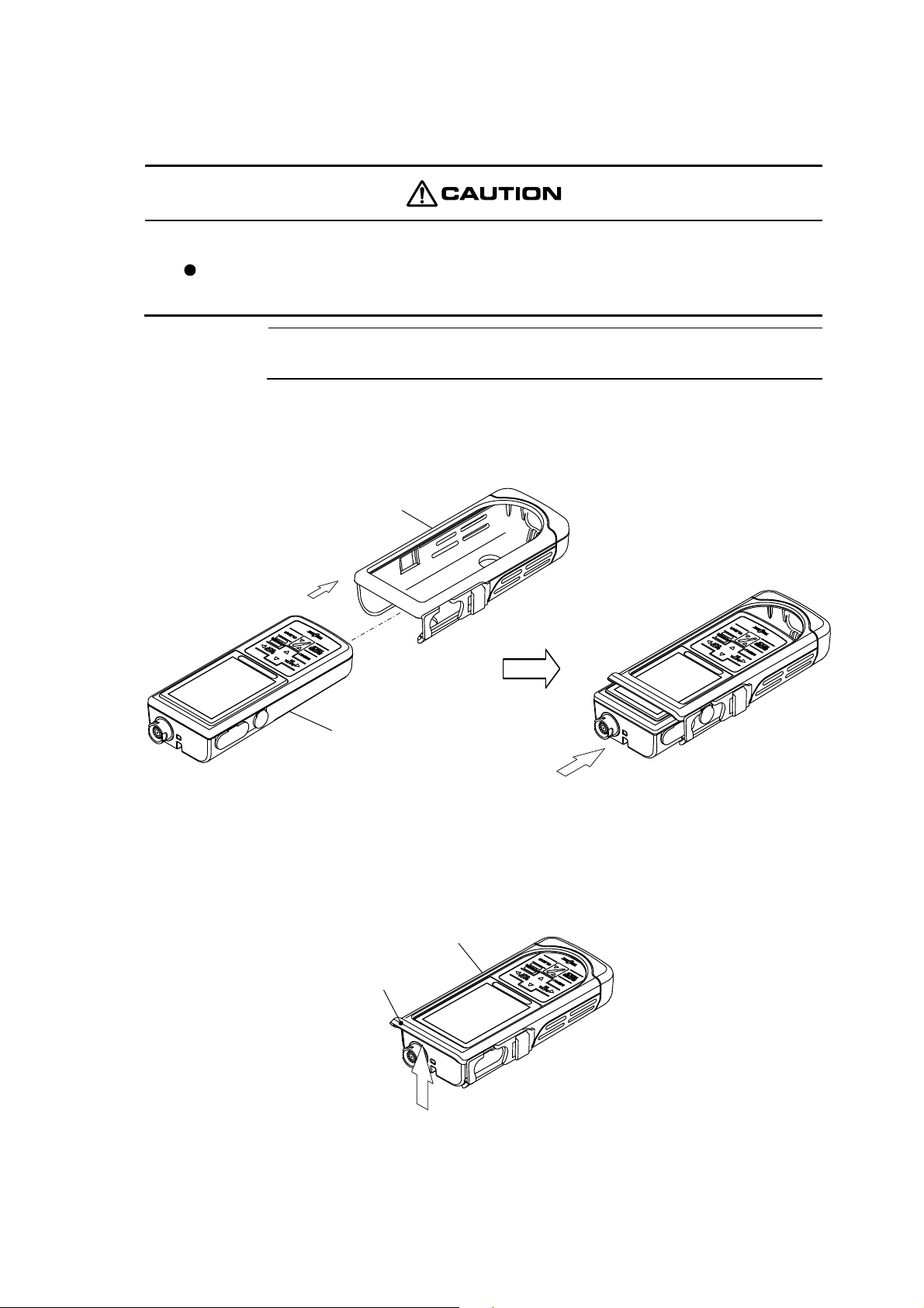
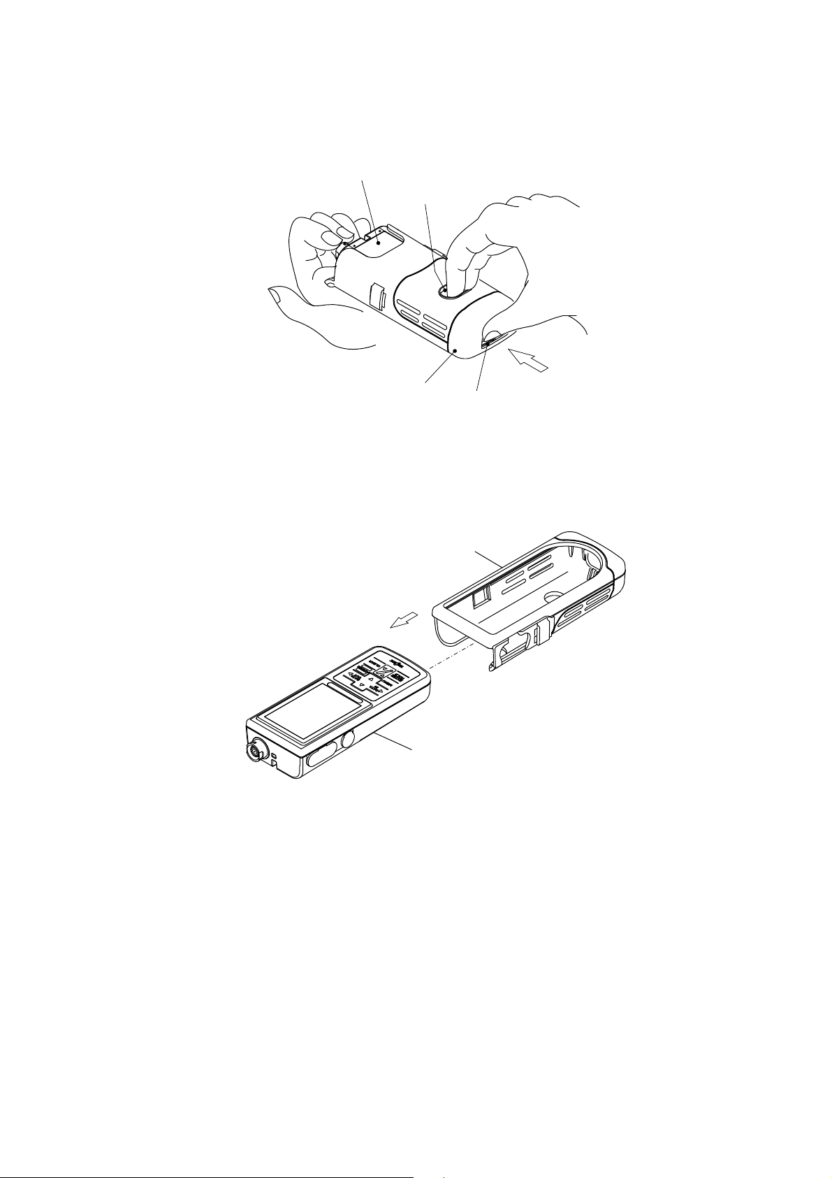
(1) Installing the protective cover
【IMPORTANT】 • Install and remove the protective cover on a desk, etc. At that time, be
careful not to drop the instrument body.
Install the accessory protective cover in accordance with the following figure so that the instrument
body is inserted all the way from the top of the protective cover.
Protective cover
Instrument body
Installing the Protective Cover
(2) Removing the protective cover
① Flip the top flap. ⋅⋅⋅⋅⋅⋅Flip up the top flap of the protective cover.
Protective cover
Top flap
Flipping Up the Top Flap
-
19 -
Model: TB-31 4.2 Installing and Removing the Protective Cover
② Push out the instrument body. ⋅⋅⋅⋅⋅⋅Insert your middle finger and index finger into the oval
hole in the back of the instrument body and push out the instrument body.
Instrument body
(rear side)
Oval hole for
inserting fingers
Protective cover
Pushing out hole
Pushing Out the Instrument Body
③ Remove the instrument body. ⋅⋅⋅⋅⋅⋅ Remove the instrument body from the protective cover.
Protective cover
Instrument body
Removing the Protective Cover
-
20 -
Model: TB-31 4.3 Turbidity Sensor Connection
4.3 Turbidity Sensor Connection
Fire and electric shock
Always verify that the power is off before connecting or disconnecting the sensor
plug, AC adapter cover, or input/output cover. Water or reagent entering the product
Waterproofing
may short the circuits and cause electric shock or fire.
The construction of the product becomes waterproof (IP67) only when the sensor,
battery cover, AC adapter cover, and input/output cover are installed properly.
Do not touch the instrument with wet hands or wash it with water when the sensor
has been removed or the battery cover, AC adapter cover, or input/output cover is
opened. Besides, do not install or store the product where water or reagent may
enter it.
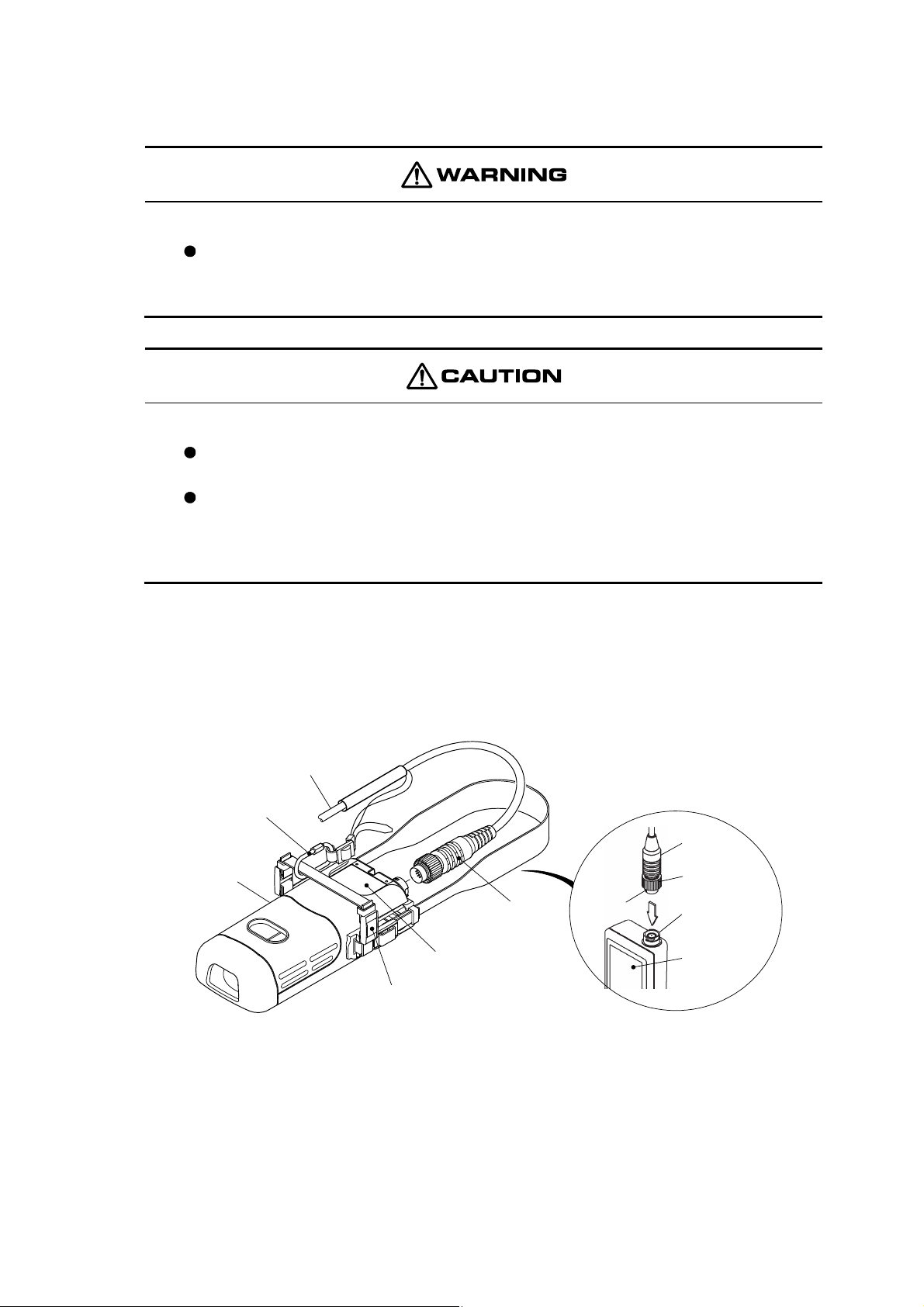
① Confirm that the power is off. ⋅⋅⋅⋅⋅⋅ Confirm that the instrument power is off.
② Insert the plug. ⋅⋅⋅⋅⋅⋅ Hold the plug so that the “O” mark at the end of the plug is facing the front
of the instrument and insert the plug straight into the sensor jack.
Sensor cable
Cable fixing
bracket
Plug
Protective
cover
Instrument body
(rear side)
Shoulder belt
Plug
○(mark)
Fixing ring
Sensor jack
Instrument
body
(front side)
Fastening the Plug and Mount the Cable Fixing Bracket
③ Fasten the plug. ⋅⋅⋅⋅⋅⋅ Fasten the plug by turning the fastener ring only. At this time, do not turn
the plug body.
-
21 -

Model: TB-31 4.3 Turbidity Sensor Connection
【IMPORTANT】 • If the plug body is turned or moved back and forth when removing and
installing the sensor plug, the pins and connector may be damaged. Pull it
straight out or push it straight in.
④ Mount the cable fixing bracket. ⋅⋅⋅⋅⋅⋅ Loose the nut of the cable fixing bracket and mount it to
the shoulder belt of the instrument body (rear side).
-
22 -

Model: TB-31 4.4 Turbidity Sensor Preparation
4.4 Turbidity Sensor Preparation
Before performing the calibration or measurements, inspect the sensor. For details, refer to 8.2
“Turbidity Sensor Maintenance”, or the instruction manual supplied with the sensor.
① Remove the protective tube. ⋅⋅⋅⋅⋅⋅ Remove the protective tube of the sensor by turning it in the
counterclockwise direction.
Sensor end
Protective tube
(counterclockwise)
Remove the Protective Tube
② Wash the light-receiving part and light-emitting part. ⋅⋅⋅⋅⋅⋅ Wash out the light-receiving part
and light-emitting part of the sensor end by pure water and wipe off them gently using tissue paper,
etc.
Light-emitting part
Beaker
Sensor
Pure water
Light-receiving part]
Wash the Light-receiving Part and Light-emitting Part by Pure Water
③ Install the protective tube. ⋅⋅⋅⋅⋅⋅ Install the protective tube of the sensor as its original state.
【IMPORTANT】 • When washing the sensor, never use cleanser or other abrasive or
ethanol or other organic solvent.
• If cleanser or other abrasive is use, the surface of the sensor will be
scratched. If ethanol or other organic solvent is used, the acryl window of
the light-receiving part and light-emitting part will become cloudy and their
performance will drop.
-
23 -
Model: TB-31 5.1 Operation Screens Map
5. Basic Operation
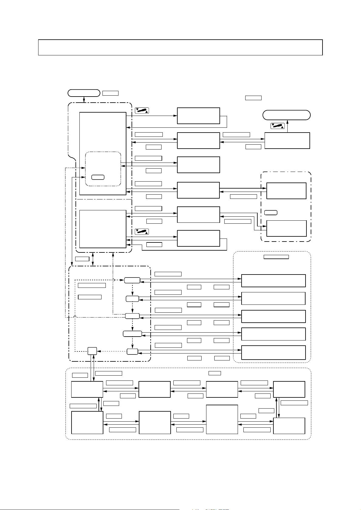
5.1 Operation Screens Map
Power on (ON)
<Measurement state>
[Real-time mode
measurement screen]
POWER
Interval
standby state*
( Blinking)
INT.
<Measurement standby state>
[Batch mode measurement
standby screen]
(Main display: ----)
MENU
[Menu screen]
DATA OUT/→
or
←/DATA IN
(reversed)
(blinking)
etc.
(Press for 2 seconds or more.)
DATA OUT/→
ENTER/HOLD
ENTER/HOLD
ENTER/HOLD
(blinking)
MODE
(blinking)
No.
<disabled>
(blinking)
INT.
<enabled>
(blinking)
CLOCK
(blinking)
C.
When pressing (less than 2 seconds) at any
screen, the display returns directly to the measurement state
(Press for 2
seconds or more.)
(Cancel)
CLEAR
CLEAR
(Cancel)
CLEAR ENTER/HOLD
(Cancel)
(Cancel)
CLEAR
(Press for 2
seconds or more.)
(Cancel)
CLEAR
[One-touch zero
calibration
execution screen]
[Memory data display
screen]
[Interval execution
screen]
[Auto hold execution
screen]
[Batch mode
measurement
execution screen]
[One-touch zero
calibration execution
screen]
(measurement standby state).
(Returns
immediately after.)
ENTER/HOLD
*When Interval setting screen is set to enabled, the display
switches to the interval standby state. When setting to
disabled (oFF), the display returns to measurement state.
(After stability check,
switches automatically.)
(After 1 minute,
switches automatically.)
ENTER/HOLD
(After 1 minute,
returns.)
ENTER/HOLD
or
MENU CLEAR
POWER
CLEAR
◎When pressing at these 5
screens, the display returns directly to the
measurement state (or measurement standby
state).
[Measurement mode setting screen]
ENTER/HOLD
[Date number setting screen]
or
MENU CLEAR
ENTER/HOLD
or
MENU CLEAR
ENTER/HOLD
[Date and time setting screen]
or
ENTER/HOLD
MENU CLEAR
or
MENU CLEAR
[Calibration execution screen]
Data continuous output
processing
[Memory data output /
erase screen]
<Hold standby state>
[Hold standby screen]
(Measurement data is always
saved at the same time as
lights.)
HOLD
[Batch mode
measurement end
screen]
ENTER/HOLD
[Interval setting screen]*
CLEAR
[Calibration
value display
screen]
ENTER/HOLD
[Auto power off
setting screen]
ENTER/HOLD
ENTER/HOLD
CLEAR
CLEAR
ENTER/HOLD
CLEAR
◎When pressing a t these 8 screens, the disp lay returns directly to the
menu screen.
[Display range
setting screen]
[Buzzer on/off
setting screen]
ENTER/HOLD
CLEAR
CLEAR
ENTER/HOLD
Operation Screens Map
-
24 -
MENU
[Measurement
unit setting
screen]
[Memory
overwrite on/off
setting screen]
ENTER/HOLD
CLEAR
CLEAR
CLEAR
ENTER/HOLD
[Response screen]
ENTER/HOLD
[Temperature
calibration screen]
Model: TB-31 5.2 Turning on the Power
S
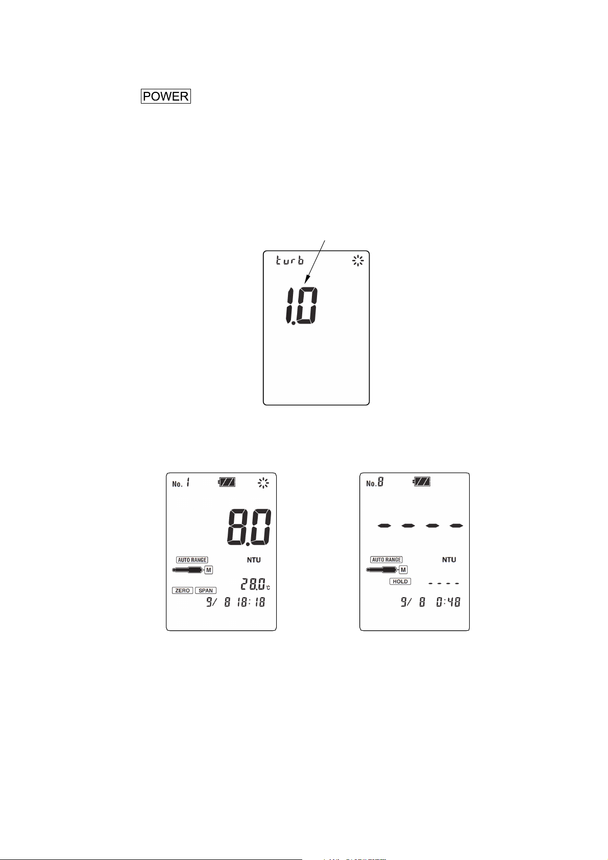
5.2 Turning on the Power
(a) Press for 2 seconds or more (until you hear a beep).
(b) When the instrument power is turned on for the first time after purchase, the real-time mode
measurement screen is displayed subsequently to the version No. display, and the instrument enters
the measurement standby state.
(c) In normal use, once the instrument power is turned off after the measurement mode was set to
batch mode measurement, when the power is turned on again, the batch mode measurement
standby screen is displayed subsequently to the version No. display and the instrument enters the
measurement standby state.
Version No.
Version No. Display Screen (example)
Real-time Mode Measurement
Screen (example)
Batch Mode Measurement
tandby Screen (example)
-
25 -

Model: TB-31 5.3 Time Setting
5.3 Time Setting
Set the current date and time in accordance with the following procedure.
Time Setting Procedure
Operation Screen example
① Display the menu screen. ⋅⋅⋅ Press at the each
screen in the measurement state or in the measurement standby
state
Year
② Cause
CLOCK
to blink by pressing or
several times.
③ Display the date and time setting screen. ⋅⋅⋅ Press
④ Set the date and time. ⋅⋅⋅ Press
• Press
• Setting range: Year…2011 to 2050
⑤ Ente r. ⋅⋅⋅ After checking the set value, press
real-time mode measurement screen or batch mode
measurement standby screen by the setting of measurement
mode.
• To return to the menu screen, press
CLOCK
on the menu screen is blinking, cause
to blink. ⋅⋅⋅ When a mark other than
.
to move the blinking point.
or and change the blinking value.
Month and day…January 1 to December 31
Time…00:00 to 23:59
. After entry, the display returns to the
.
CLOCK
or
Month
and day
Hour and
minute
(24H system)
[Date and time setting
screen]
-
26 -
 Loading...