

Page 1
SIP VIDEO INTERCOM
INSTRUCTION MANUAL
N-SP80 Series
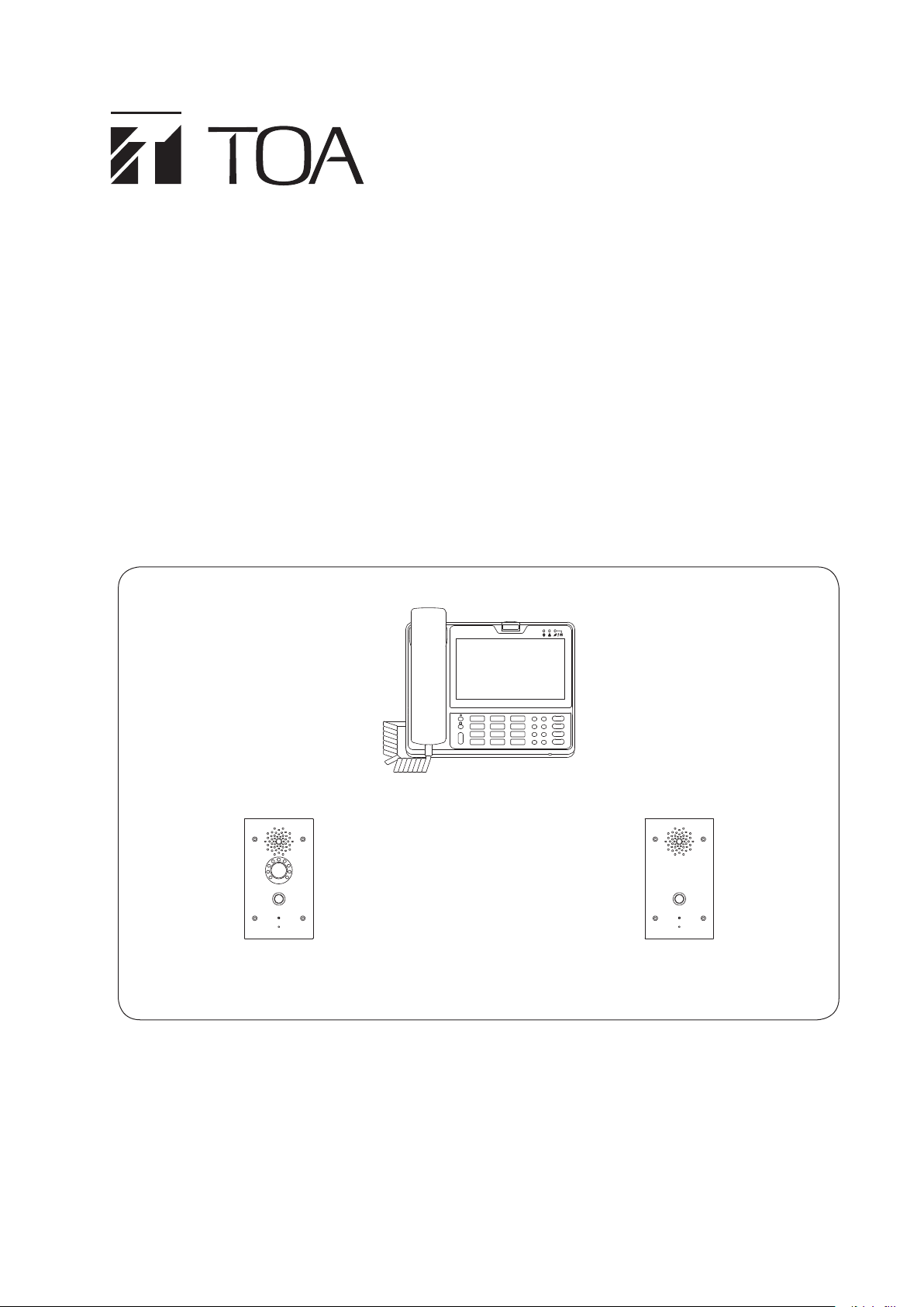
SIP MULTIMEDIA STATION
SIP VIDEO DOOR STATION
SIP AUDIO DOOR STATION
4 SIZE BACK BOX
N-SP80MS1
N-SP80MS1
N-SP80VS1
N-SP80AS1
YC-400
N-SP80VS1 N-SP80AS1
Thank you for purchasing TOA’s SIP Video Intercom.
Please carefully follow the instructions in this manual to ensure long, trouble-free use of your equipment.
Page 2

TABLE OF CONTENTS
1. SAFETY PRECAUTIONS
............................................................................. 4
2. GENERAL DESCRIPTION .......................................................................... 4
4. HANDLING PRECAUTIONS ...................................................................... 5
5. USAGE MODE .................................................................................................... 6
5.1. SIP Server Mode ................................................................................................... 6
5.2. Peer-to-Peer Mode ............................................................................................... 6
6. NOMENCLATURE AND FUNCTIONS ................................................. 7
6.1. N-SP80MS1 ........................................................................................................... 7
Front ...................................................................................................................... 7
Rear ...................................................................................................................... 8
Right side .............................................................................................................. 8
6.2. N-SP80VS1, N-SP80AS1 ...................................................................................... 9
Front ...................................................................................................................... 9
Rear ...................................................................................................................... 9
7. LIST OF SYSTEM FUNCTIONS ............................................................. 10
7.1. Basic Functions ................................................................................................... 10
8. SUMMARY OF THE PAGING FUNCTION ...................................... 12
8.1. Paging Configuration ........................................................................................... 12
8.2. Priority Setting of Paging and Conversation ....................................................... 12
9.
MULTIMEDIA STATION'S FUNCTIONS AND OPERATIONS
9.1. Basic Usage ........................................................................................................ 13
9.2. Conversation's Functions and Operations .......................................................... 15
9.3. Paging Call Operation ......................................................................................... 23
9.4. Other Functions and Operations ......................................................................... 24
... 13
10. DOOR STATION'S FUNCTIONS AND OPERATIONS .......... 27
10.1 Functions for Conversations and Operations ..................................................... 27
10.2. Paging Function ................................................................................................ 27
10.3. Other Functions and Operations ....................................................................... 28
11. INSTALLATION ............................................................................................. 29
11.1. Safety Precautions for The Multimedia Station .................................................. 29
11.2 Installation of Door Station ................................................................................. 30
12. CONNECTION ................................................................................................ 31
12.1. N-SP80MS1 ....................................................................................................... 31
12.2. N-SP80VS1, N-SP80AS1 .................................................................................. 33
13. SYSTEM SETTING USING A WEB BROWSER ....................... 35
13.1. Before Performing System Setting .................................................................... 35
13.2. Confirming the IP Address of Each Device ....................................................... 35
13.3. N-SP80MS1 Setting .......................................................................................... 36
13.4. N-SP80VS1 and N-SP80AS1 Settings .............................................................. 55
2
Page 3

14. TROUBLE SHOOTING .............................................................................. 72
15. SPECIFICATION ............................................................................................ 73
15.1. N-SP80MS1 SIP Multimedia Station ............................................................... 73
15.2. N-SP80VS1 SIP Video Door Station ............................................................... 74
15.3. N-SP80AS1 SIP Audio Door Station ............................................................... 75
15.4. YC-400 4 Size Back Box ................................................................................. 76
3
Page 4

1. SAFETY PRECAUTIONS
• Before installation or use, be sure to carefully read all the instructions in this section for correct and safe
operation.
• Be sure to follow all the precautionary instructions in this section, which contain important warnings and/or
cautions regarding safety.
• After reading, keep this manual handy for future reference.
Safety Symbol and Message Conventions
Safety symbols and messages described below are used in this manual to prevent bodily injury and property
damage which could result from mishandling. Before operating your product, read this manual rst and
understand the safety symbols and messages so you are thoroughly aware of the potential safety hazards.
CAUTION
• Use the specied AC adapter and PoE switching hub for the unit. Note that the use of another adapter and
PoE switching hub may cause a re. (N-SP80MS1 only)
• Avoid touching the unit’s sharp metal edge to prevent injury. (N-SP80VS1, N-SP80AS1, and YC-400)
• Use the 12 V DC power supply and PoE switching hub for the unit. Note that the use of another adapter and
PoE switching hub may cause a re. (N-SP80VS1 and N-SP80AS1 only)
Indicates a potentially hazardous situation which, if mishandled, could
result in moderate or minor personal injury, and/or property damage.
2. GENERAL DESCRIPTION
The N-SP8 0 se r i e s intercom system is de s i g n e d for use in combination with the SI P (Session Init i a t i o n Protocol)
Intercom system.
This system consists of the Android based touch panel multimedia stations and the door stations. The door
station is available in 2 models: the one with camera and the one without camera.
The system can be used not only in SIP server mode but also in peer-to-peer mode: the former enables the
system to work by connecting to the SIP server and the latter enables it to work without using the SIP server.
In this manual, the N-SP80MS1 is described as the multimedia station, and the N-SP80VS1 and the N-SP80AS1
are collectively described as the door station.
Note: Android is a trademark of Google LLC.
4
Page 5

3. FEATURES
• Fully compliant with SIP.
• Connected to the network via Ethernet.
• The door station with camera is compatible with ONVIF.
• Supports 2 ways of connection: Connection to the SIP server using SIP and peer-to-peer connection.
• Supports the following audio codecs: G.711, G.722, and G.729.
(Audio codec is xed to G.722 when in peer-to-peer connection.)
• Can be powered by means of PoE or from the DC power supply unit.
• The camera incorporated in the door station with camera has 3 mega pixels, featuring the built-in infrared light
that allows images to be taken at night.
• The built-in acoustic echo canceller ensures full duplex conversation for the door stations.
• The door stations are equipped with a relay output function. Relay control can be performed from a multimedia
station or other SIP telephones.
• The door stations are equipped with an external control input function. Different types of calling can be made
when an external control switch is connected.
• The multimedia station is easy to operate on the screen thanks to a touch panel and GUI (Graphical User
Interface) design, and in addition, usable as a telephone by intuitive dial operation with a ten-key pad.
• The multimedia station is selectable one of 3 conversation methods: handset conversation, hands-free
conversation, and headset conversation.
• Compatibility with CUCM obtained by Cisco systems.
• Easy conversations between stations even under high noise environment.
Note: Cisco Systems is a registered trademark of Cisco Systems, Inc. in the United States and certain other
countries.
4. HANDLING PRECAUTIONS
The transmission quality of the internet is not always guaranteed.
Therefore, when this system is connected via the internet, the following symptoms may happen when the
network is congested.
• Packet loss
• Interruption of speech voice
• Generation of noise
5
Page 6
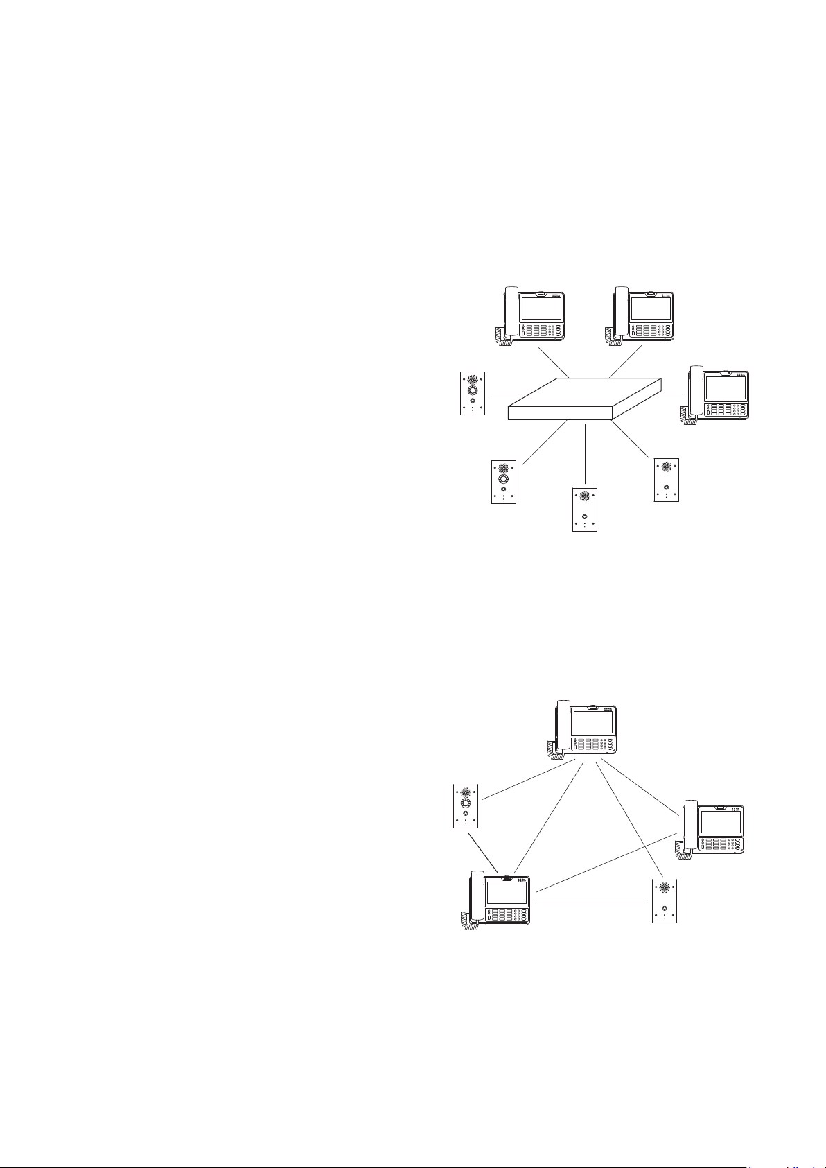
5. USAGE MODE
5.1. SIP Server Mode
Each equipment of this system is in full conformity with SIP and can be used in connection to the SIP server
(Telephone system). The SIP server mode refers to the system when connecting to the SIP server. The
connection to CUCM by Cisco Systems and Asterisk by Digium is conrmed for the N-SP80 series. Since the
supporting version and the SIP server need to be updated, check for the latest information on the TOA product
data download site (https://www.toa-products.com/international/).
Note: Asterisk is a trademark of Digium, Inc.
[Features of SIP server mode communication]
• Audio signals are directly communicated between stations.
(They may be communicated via the server.)
• The maximum number of the stations to be connected
depends on the SIP server's specication.
• Communications are centrally controlled by the server.
• Transfer function can be used depending on the SIP server's
specication.
• Connection to the outside line is possible depending on the
SIP server's specication.
[SIP server mode]
SIP server
5.2. Peer-to-Peer Mode
The devices of this system can be directly connected with each other without using the SIP server. Peer-to-Peer
mode refers to the system or the state where the stations are directly connected with each other without using
a SIP server.
[Features of Peer-to-peer mode communication]
• Multiple one-to-one communications can be made
simultaneously, enabling the number of the connectable
stations within the system to be unlimited.
• SIP server is not used, allowing suppression of introduction
costs.
• A 3 party conversation can be made.
• Audio codec is xed to G.722.
[Peer-to-peer mode]
6
Page 7
6. NOMENCLATURE AND FUNCTIONS
6.1. N-SP80MS1
• Desktop design
• Handset, Hands-free (with AEC function), Headset connectable
• Built-in touch panel
• PoE-compatible (IEEE802.3af compliant)
• Built-in camera
[Front]
4
1
10
11
1. Power ON/OFF button
Press this button to turn on the power and pressing
it again will place the unit in sleep state.
Holding it down for 1 second or more allows the
selection of either restarting the unit or setting the
manner mode.
2. Indicators
Indicate the following operation states.
: Indicates the unit ’s power ON or OFF state.
The unit is operating when the indicator is
lit, and not operating when it is unlit.
: Indicates the network connection state.
Connection to a LAN is established when
the indicator is lit, and not established
when it is unlit.
: Indicates the absence incoming call/
unread message state.
The absence incoming call or unread
messages are present when the indicator
is ashing, and not present when it is unlit.
3. Camera
A built-in camera with 2 mega pixels.
Used when making conversation between multimedia
stations.
4. Handset
Used for handset conversation.
5. Touch panel
A 7" touch panel screen.
12
3
2
13
14
17
18
5
15
16
19
20
6
7
8
9
6. Home button
Returns the display to the home screen.
7. Menu button
Indicates the setting items on the screen.
8. Back button
Returns the display to the last screen you viewed,
or the home screen.
9. Speaker button
Press this button to start hands-free conversation.
10. Sl ee p button
Press this button to place the unit in sleep state.
Holding it down for 1 second or more allows the
selection of either restarting the unit or setting the
manner mode.
11. Volume control button
Adjusts the volume level of the built-in speaker.
12. Numerical keypad
Used to enter the numbers.
13. De let e button
Deletes one by one the dial numbers entered
when making a call or the characters entered
when registering.
14. Message button
Press this button to read or write the short message.
(Only when in the SIP server mode)
7
Page 8
15. Confe ren ce button
Starts the three-party conversation function.
16. Transfer button
Starts the transfer function during conversation.
(Only when in the SIP server mode)
18. C ontac t button
Press this button when registering or selecting
the telephone book.
19. Hold button
Starts the hold function during conversation.
17. OK button
Conrms the selection on the screen while in the
touch panel operation.
20. Mute button
Mutes the hands-free microphone and the
handset microphone.
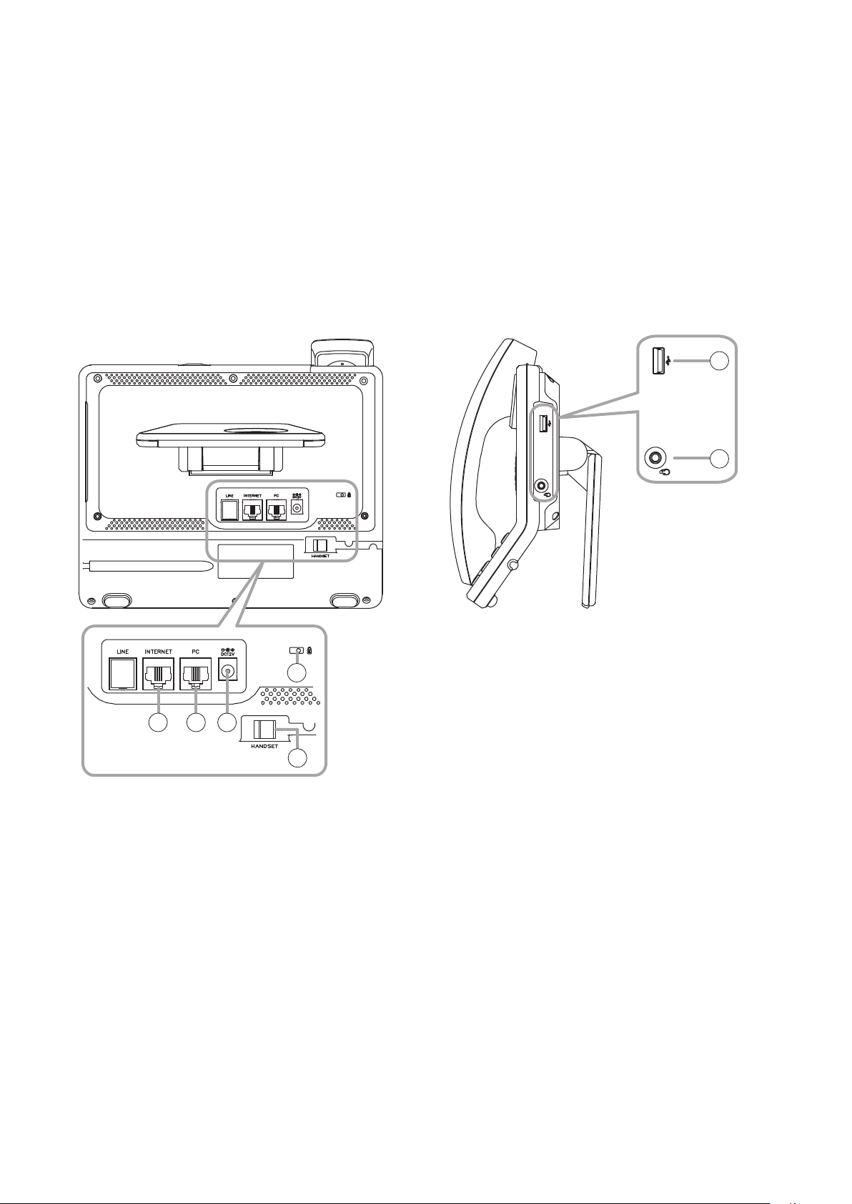
[Rear] [Right side]
26
27
24
21 22 23
25
21. LAN connection terminal
Connect the LAN cable to this terminal.
This terminal can be connected to PoE switching
hub.
22. PC connection terminal
Connect a PC to this terminal.
23. DC input terminal
Connect the AC adapter* to this terminal.
* Use the optional AD-1215P or its equivalent.
24. Security slot
Used to connect the security wire such as a theft
preventing wire.
This is a Kensington lock slot.
25. Handset connection terminal
Connect the handset to this terminal.
26. USB connection terminal
Connect a USB device to this terminal.
27. Headset connection terminal
Connect a headset to this terminal.
20 mW, 16 Ω/32 Ω, ø3.5 mm mini jack (3P)
8
Page 9
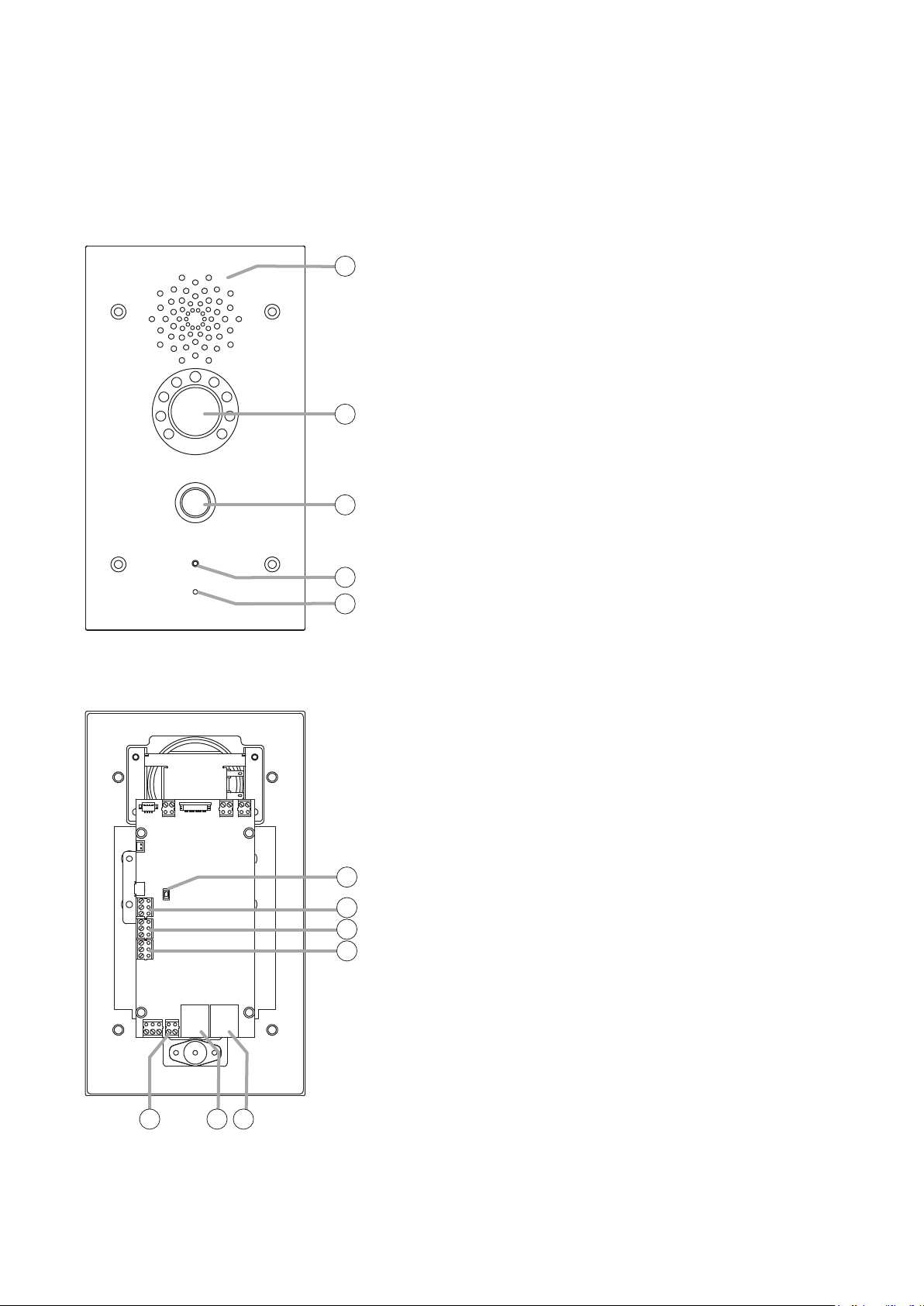
6.2. N-SP80VS1, N-SP80AS1
• Designed for wall-recessed installation (YC-400 is required.)
• Hands-free (with AEC function) type
• Call button x 1, Relay output x 2, External control input x 2
• PoE compatible (IEEE802.3af compliant)
• Equipped with a camera, luminance sensor, and infrared light (N-SP80VS1 only)
[Front]
1. Speaker
1
2
3
O u t pu t s s pe e c h v o i c e f r o m t h e p a r t n er s t a t i o n d u r i n g c o n v e r s a t i o n .
2. Camera (N-SP80VS1 only)
A built-in camera with 3 mega pixels.
Used when making conversation with a multimedia station.
3. Call button
Press this button to start conversation.
Pressing this button will call the preset partner station.
4. Operation indicator
Lights or ashes during conversation or during a call from this
door station.
( The indication color and when the indicator lights or ashes can
be changed by the setting.)
The gure shows the N-SP80VS1.
[Rear]
5. Microphone
4
5
6
7
8
9
Picks up the speaker’s voice during conversation, which is then
sent to the partner station.
6. Reset button
Press this button to restart the station.
Holding down this button for 5 seconds or more restarts the door
station in the default state. (The settings data will be initialized.)
7. External control inputs 1 and 2
A special calling can be performed by connecting an external
control switch or sensor output to this terminal.
8. Relay 1 connection terminal
The relay output can be controlled by the specic dial code
from the partner station during conversation. Used to unlock the
nearby door. (An appropriate dial code can be set.)
9. Relay 2 connection terminal
Has the same function as the Relay 1 connection terminal (8).
10 11 12
The gure shows the N-SP80VS1.
10. DC power input terminal
The door station can be operated by inputting 12 V DC to this
terminal.
11. Ethernet connection terminal
Used when connecting to the network.
12. Ethernet connection terminal (PoE compatible)
Used when connecting to the network.
Power can be supplied when this terminal is connected to the
PoE switching hub.
9
Page 10

7. LIST OF SYSTEM FUNCTIONS
7.1. Basic Functions
7.1.1. List of the N-SP80MS1's functions
Function General description
Call Making a call
(Call by direct dialing)
Making a call
(Call from the phone
book)
Receiving a call You can select either "Response only with
Rejecting an incoming
call
Call option Operation of such as holding, microphone
Video option Operation of such as screen resizing, self-
Call log You can check call logs and make a call
Transfer
(Blind transfer)
Transfer
(Attended transfer)
Paging Paging Call You can make a paging call. Paging is
Others 3 party conference Conversation among 3 parties can be
Connecting to a thirdparty VoIP
Connection with
outside line
Door remote control The relay output can be controlled by
You can make a call by directly pressing the
other party's phone number (or IP address)
using the numerical keypad (or touching
the ten keys on the touch panel).
Call can be made from the phone book
registered in advance. p. 16 p. 49
audio " or "Response using video" for a call
reception.
You can reject an incoming call.
muting, and video switching can be made
during conversation.
view display, and other party view display
can be made during video conversation.
from the call history, too.
A method to transfer a call without
conrming with the transfer destination
party. Can be used when in SIP server
mode.
A method to transfer a call after conrming
with the transfer destination party in
advance. Can be used when in SIP server
mode.
performed using Multicast audio from a
multimedia station.
made. Can be used when in SIP server
mode.
Can be connected to a third-party VoIP.
Connection with outside line can be made.
Can be used when in SIP server mode.
entering the preset dial code during
conversation with the door station. Can be
used to unlock the nearby door.
Reference page
Operation Setting
p. 15
p. 17
p. 18
p. 18
p. 18 p. 44
p. 19 p. 51
p. 21
p. 22
p. 23
p. 24
p. 26
p. 26
p. 26
10
Page 11

7.1.2. List of the N-SP80VS1's and N-SP80AS1's functions
Function General description
Call Making a call You can make a call by pressing the Call
button.
Receiving a call Call reception is automatically responded.
Cancelling a call and
conversations
Paging Paging function Paging call is received automatically. Audio
Others No answer forward
function
Time limit Maximum duration of calling time and
Door remote control The relay output built in the door station can
Call activation from
an external device
Change in various
function sounds
Pressing the Call button during a call or
conversation cancels the current operation.
signals are output when the preset multicast
address receives the audio stream.
Up to 3 call destinations can be assigned
to the Call button by setting the order. If the
rst called station is absent, then the 2nd
one will be called. When the 2nd one is
also absent, then the 3rd one will be called.
conversation time can be set.
be controlled from the multimedia station.
Can be used to unlock the nearby door.
A different call can be made when inputting
signals from the external device to the door
station's external control input.
Call transmission sound, call reception
sound, and door remote control sound can
be changed. Can be changed by updating
the sound le.
Reference page
Operation Setting
p. 27 p. 57
p. 27
p. 27 p. 57
p. 27 p. 68
p. 28 p. 57
p. 28 p. 57
p. 28 p. 59
p. 29 p. 59
p. 29 p. 67
11
Page 12
8. SUMMARY OF THE PAGING FUNCTION
8.1. Paging Configuration
(N-SP80MS1)
N-SP80VS1(1) N-SP80VS1(2)N-SP80AS1(1)
Multicast audio stream transmission.
Multicast port opens.
Multicast’s address and port are matched.
Audio signals are output.
(Example)
N-SP80MS1 Transmission address/Port
239.0.0.0:5004
N-SP80VS1 (1) Reception address/Port
239.0.0.0:5010
N-SP80AS1 (1) Reception address/Port
239.0.0.0:5004
N-SP80VS1 (2) Reception address/Port
239.0.0.0:5004
The N-SP80MS1’s audio signals are
output from the N-SP80AS1 (1) and
N-SP80VS1 (2).
8.2. Priority Setting of Paging and Conversation
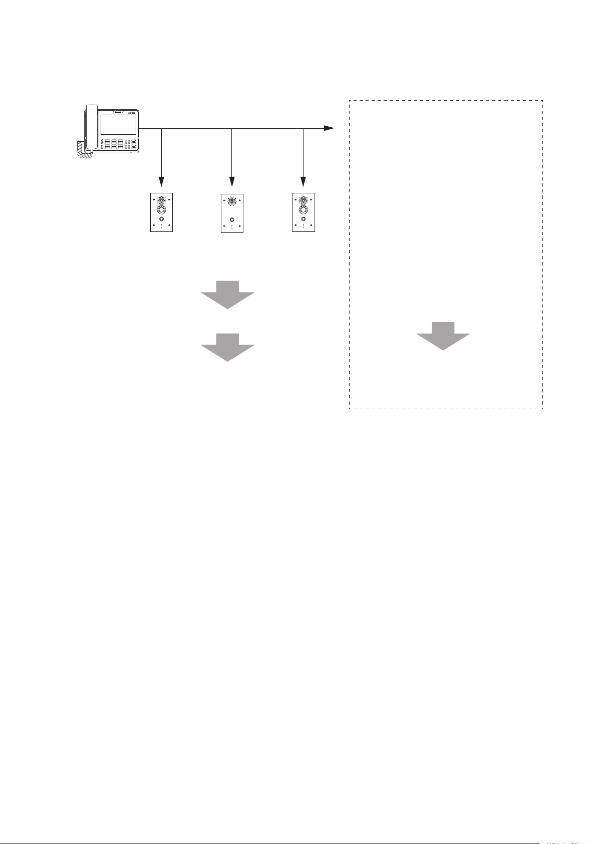
Paging call made from the multimedia station can be received through each station's speaker.
The priority level of paging call and conversation can be set for each station. (See p. 68.)
12
Page 13
9. MULTIMEDIA STATION'S FUNCTIONS AND OPERATIONS
9.1. Basic Usage
Tip
This device runs on Android OS. Perform settings such as clock by clicking the Setting icon.
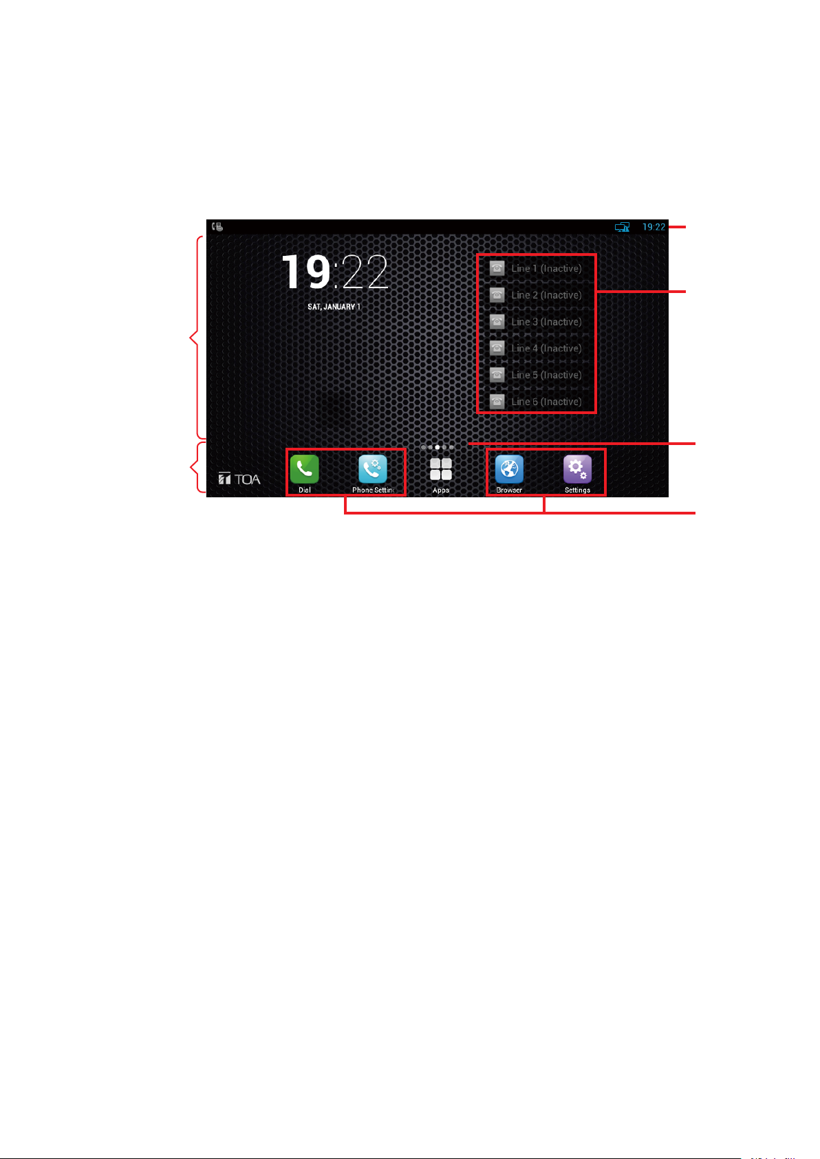
9.1.1. Main screen
Main area
Dock area
(1)
(2)
(3)
(4)
1. Status bar
Located at the upper most of the screen and displays the system status information.
2. Accounts
The multimedia station supports 6 accounts. The Account list displays the most recent account statuses.
3. Expanded screen prompt
Displays the location of the current screen page and how many pages the screens are expanded.
4. Shortcuts
Up to 4 shortcuts can be arranged in the dock area. Any number of shortcuts can be arranged in the main
area.
You can replace the arranged shortcut by dragging a new one to any region as shown above.
13
Page 14
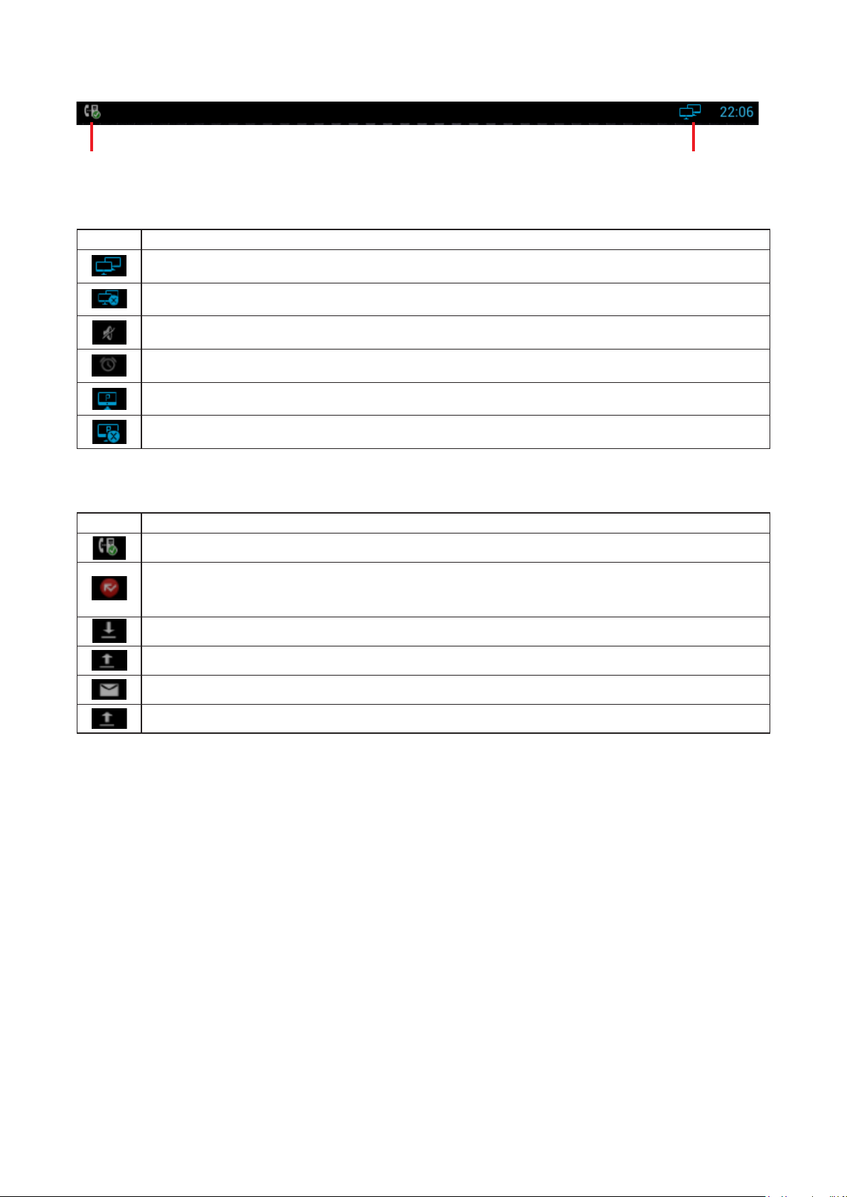
9.1.2. Status and notification display
(2) (1)
1. Status area
Icon Description
Connection to network has been established.
Connection to network is not established.
Mute mode
Alarm clock setting has been completed.
Connection by PPPoE has been established.
PPPoE connection has failed.
2.Noticationarea
Icon Description
SIP account has been registered.
Unconrmed incoming calls exist.
Note: You can check the number of unconrmed incoming calls by swiping down on the
notication area. (See p. 19.)
Downloading
Uploading
A new mail has been received.
An incoming event are being received.
14
Page 15
9.2. Conversation's Functions and Operations
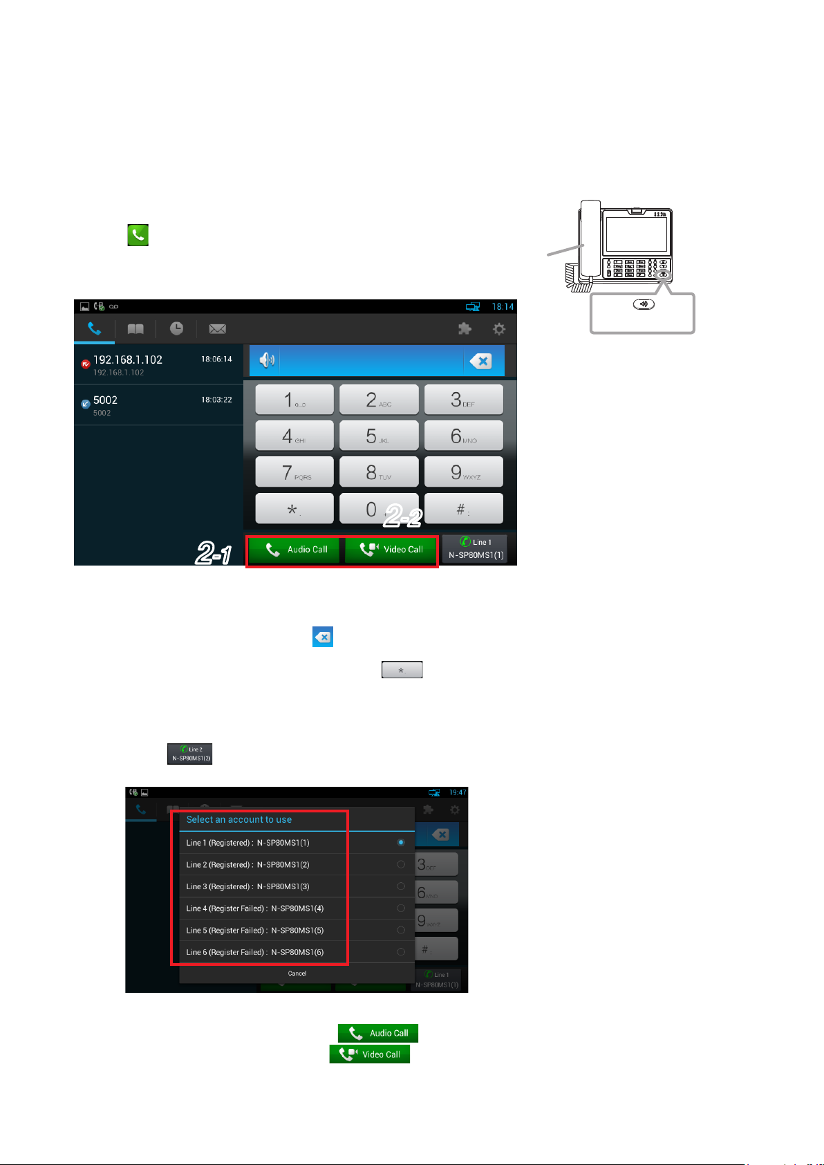
9.2.1. Making a call (Call by direct dialing)
You can make a call directly using the station’s ten keys or using the ten keys, contact list, or call history on the
dial screen.
The dial screen can be displayed by one of the following operations.
• Lift the handset.
• Press the station's Speaker button.
• Touch on the main screen.
Handset
(Dial screen)
Speaker button
2
-2
2
-1
Step 1. Enter the call destination number using the ten keys on the dial screen or the station's ten keys.
Tips
• To delete the number, press
The number is deleted one by one.
• Period can be entered by holding down for one second or more.
[When multiple SIP accounts have been registered in SIP server mode]
The accounts can be switched and used.
Touch on the dial screen, then select the account number to be switched to on the displayed
screen.
on the dial screen or the station's Delete button directly.
Step 2. Make a call.
2-1. When making an audio call, touch on the dial screen.
2-2. When making a video call, touch on the dial screen.
15
Page 16
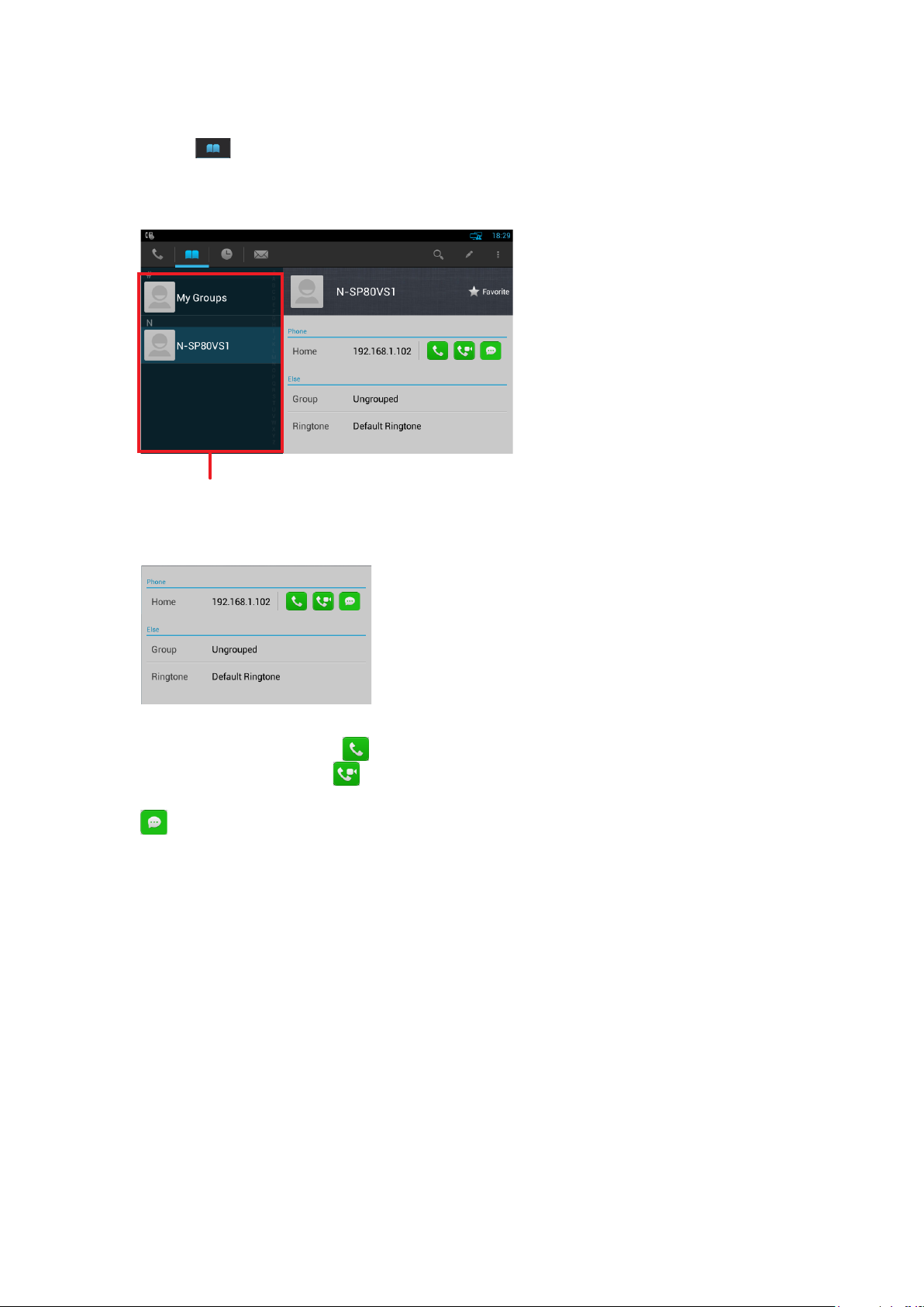
9.2.2. Making a call (Call from the phone book)
You can make a call to the contact on the dial screen.
Step 1. Touch [ => Local Phone Book => All Contacts…] on the dial screen.
The contact list appears on the left side of the dial screen.
Tip
The contact can be searched promptly with the rst character you enter.
Contact list
Step 2. Touch the desired contact to talk in the Contact list.
Details can be viewed in the window on the right side of the screen.
Step 3. Call the contact you touched.
3-1. To make an audio call, touch
3-2. To make a video call, touch .
Tip
is not used.
.
16
Page 17
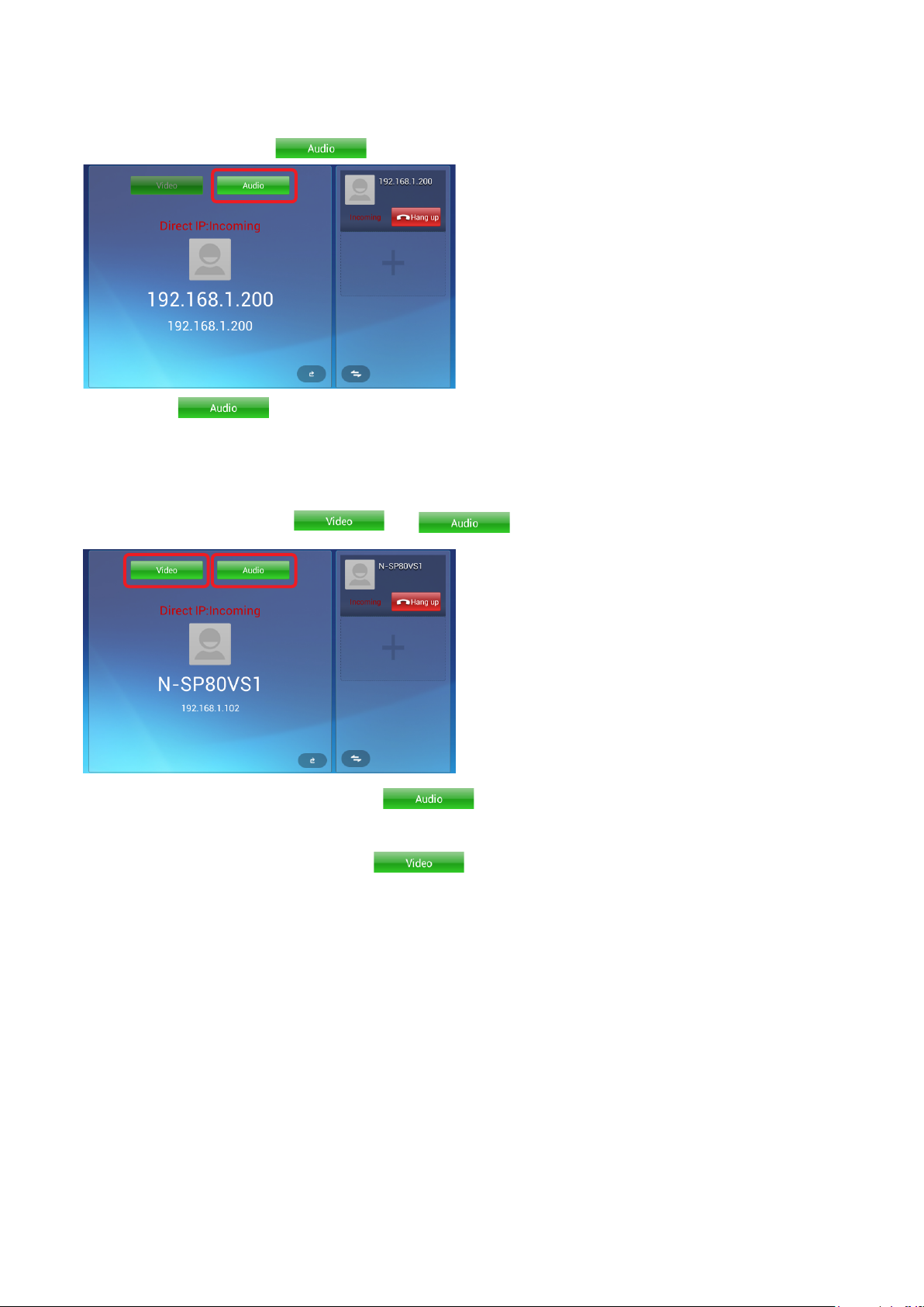
9.2.3. Receiving a call
[When receiving an audio call]
When an audio is received, becomes active.
Step: To u c h or lift the handset to answer the call.
[When receiving a video call]
When a video call is received, and become active.
Step 1. To make an audio response, touch .
Note: Images cannot be viewed.
Step 2. To make a video response, touch
Images can be viewed.
Then, you can start handsfree conversation. You can also make conversation with the caller by using
the headset or lifting the handset.
.
17
Page 18
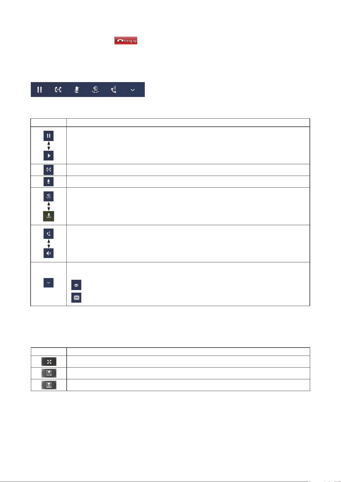
9.2.4. Rejecting an incoming call
To reject an incoming call, touch on the call screen.
9.2.5. Call option
Call options are displayed by the icons as shown below.
The table below shows the descriptions of the call options.
Icon Description
Switches the current call between Hold and Restart each time the icon is touched and the
display of the icon changes as well.
Activates the transfer function.
Mutes the microphone.
Switches between Video call and Audio call each time the icon is touched and the display of
the icon changes as well.
Switches between speaker (handsfree) and handset conversations each time the icon is
touched and the display of the icon changes as well.
Extended function.
2 icons below appear when this icon is touched.
: Activates the 3 party conference function.
: Starts recording of conversations.
9.2.6. Video option
Images can be switched by the icon operation on the video screen during video conversation.
Icon Description
Switches to the full screen.
Displays the local video.
Displays the image of the conversation partner.
18
Page 19
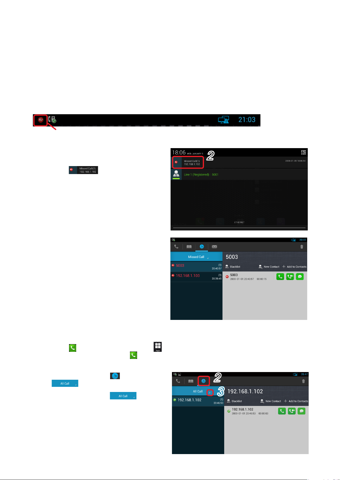
9.2.7. Call log
You can make the following 4 actions using the call logs.
• Checking the unconrmed incoming call information notication displayed on the status bar
• Checking the call logs from the call history
• Registering a new contact from the call history
• Adding the phone number to the existing Contact list
Shown below is operation.
[Checking the unconfirmed incoming call information notification displayed on the status bar]
Unconrmed incoming call information notication
Step 1. Swipe down on the status bar.
The Notication screen opens.
Step 2. Touc h .
You can view the call history.
2
[Checking the call logs from the call history]
Step 1. Touc h on the main screen, or touch
on the main screen and select .
A Dial screen opens.
Step 2. Touch the call log icon .
and the call history appear.
Step 3. Touch triangle mark of .
Types of call logs appear in a pull-down
menu.
You can select the type of call logs to
be conrmed from All Call, Missed Call,
Received Call, Dialed Call, and Forwarded
Call.
2
3
19
Page 20
Step 4. Touch the type of call logs to be conrmed
from the pull-down menu.
Touching it causes the call history to appear
on the left side of the screen, displaying the
total number of the logs in parentheses.
Step 5. Touch the phone number or contact to be
conrmed.
The touched phone number or details of all
call logs remained in the contact history can
be viewed in the window on the right side of
the screen.
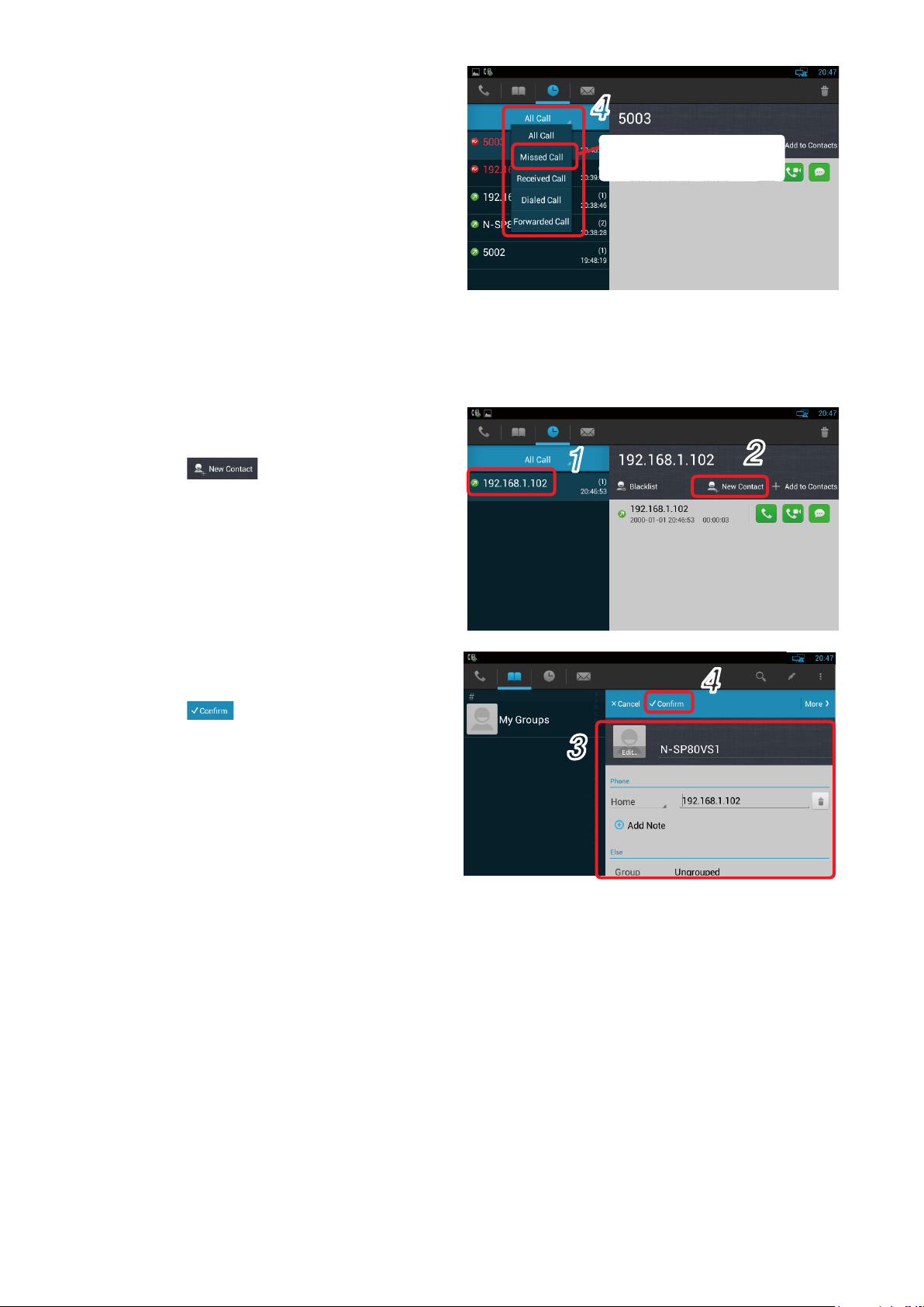
[Registering a new contact from the call history]
Step 1. Touch the number to be registered from the
call history.
4
When you want to check
the history of Missed call
Step 2. Touc h .
A registration page for a new contact
appears.
Step 3. Input the necessary items through a touch
panel.
Step 4. Touc h .
A new contact list is created, saving the
contact.
1
3
2
4
20
Page 21
[ Adding the phone number to the existing
Contact list]
Step 1. Touch the phone number to add to the
existing Contact list from the call history.
Step 2. Touc h .
A Contact list screen appears.
Step 3. Select the contact of which phone number
you want to add.
The detailed screen of the selected contact
appears.
Step 4. Enter the phone number to add in the
displayed screen.
Step 5. Touc h .
The phone number is added to the Contact list.
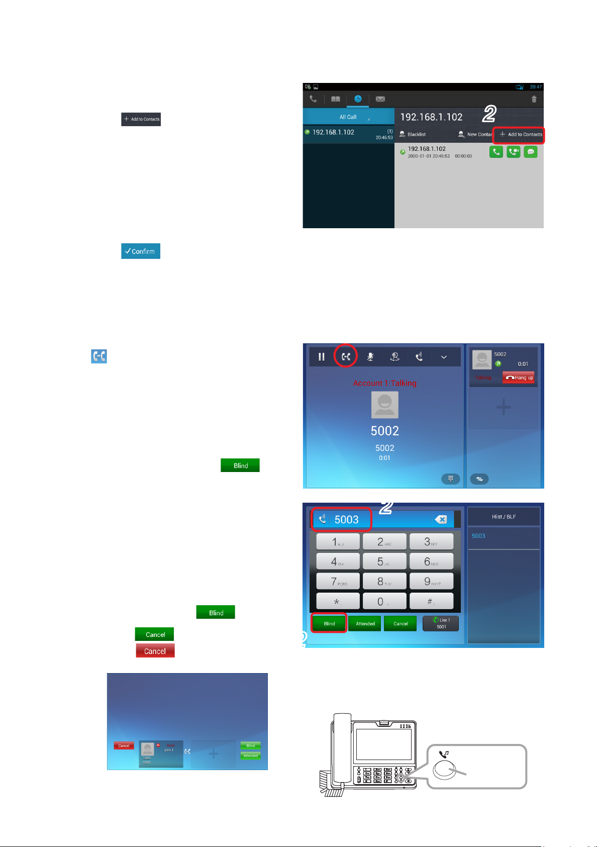
9.2.8. Transfer (Blind transfer): Unconfirmed transfer (When in SIP server mode)
Shown below is the procedure to transfer a call without communicating with the transfer destination party.
Step 1. Press the station’s Transfer button or touch
on the screen during conversation.
A dial screen for entering the phone number
of the transfer destination party appears.
Conversations between the own station and
the other party to be transferred are placed
on hold.
2
Step 2. Enter the phone number of the transfer
destination party, then touch .
The transfer destination party is called,
then both transferred and transfer
destination stations are engaged in
direct communications with each other,
terminating the own station call.
[Returning to the original conversation
without transfer]
The original conversation is restored by
following the procedures (1) through (3)
below without touching .
(1) Touch on the screen in Step 2.
(2) Touch
below.
on the displayed screen
2
2
(3) Press the unit's Hold button (gure at
right).
Hold button
21
Page 22
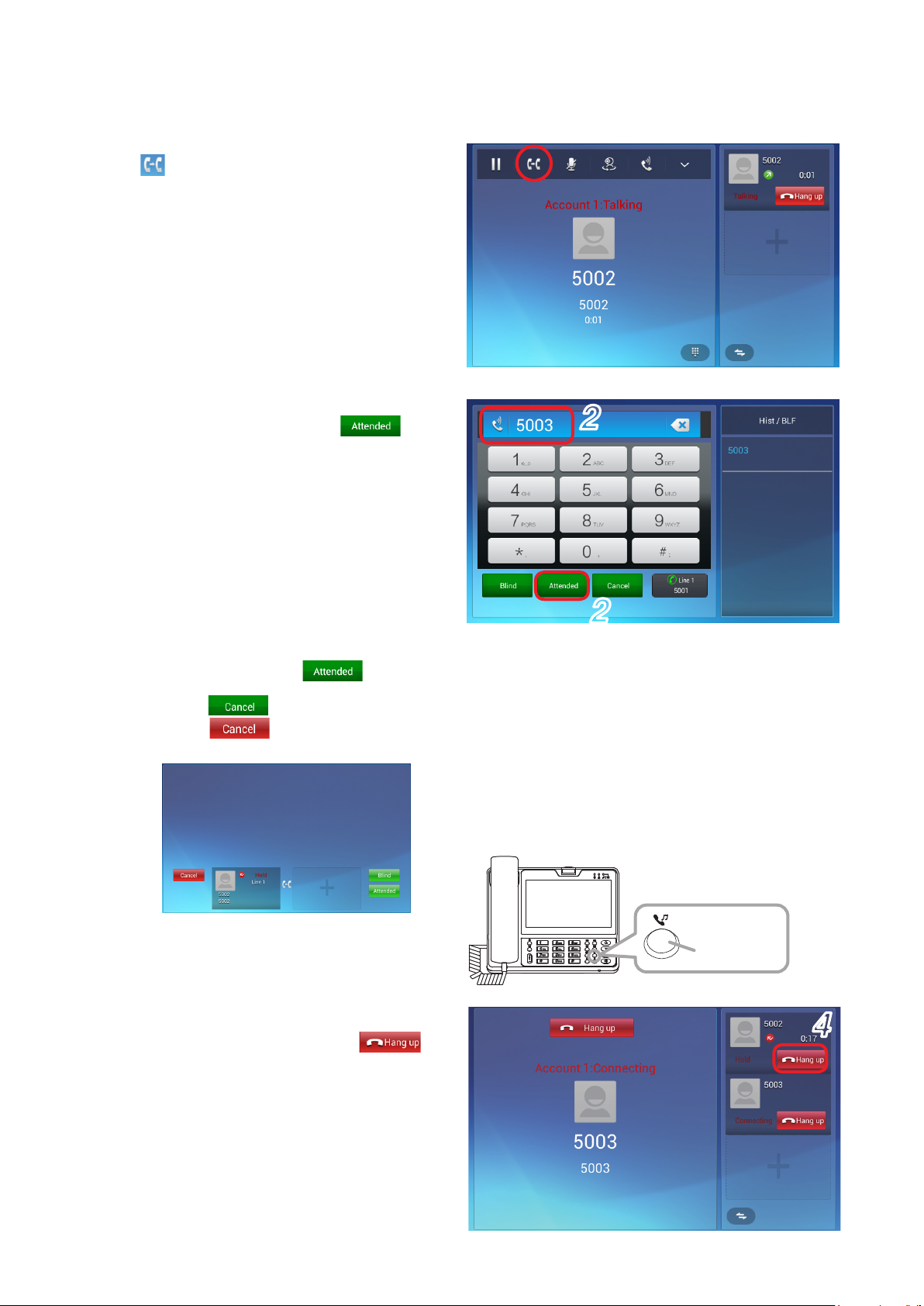
9.2.9. Transfer (Attended transfer): Confirmed transfer (When in SIP server mode)
Shown below is the procedure to transfer a call after making conversations with the transfer destination party.
Step 1. Press the station's Transfer button or touch
on the screen during conversation.
A dial screen to call the transfer destination
station is displayed and the conversations
between the own station and the other party
to be transferred are placed on hold.
Step 2. Enter the phone number of the transfer
destination party, then touch .
A conversation screen with the transfer
destination station appears.
[ Returning to restore to the original
conversation without transfer]
The original conversation is restored by
following the procedures (1) through (3)
below without touching .
(1) Touch on the screen in Step 2.
(2) Touch
below.
on the displayed screen
2
2
(3) Press the unit's Hold button (gure at
right).
Step 3. Make conversations with the transfer
destination partner.
Step 4. Hang up the handset or touch
end the conversation.
The station that was placed on hold (Station
No. 5002 in Step 1 above) and the transfer
destination station (Station No. 5003 in
Step 2 above) are connected, enabling to
start conversations.
to
Hold button
4
22
Page 23
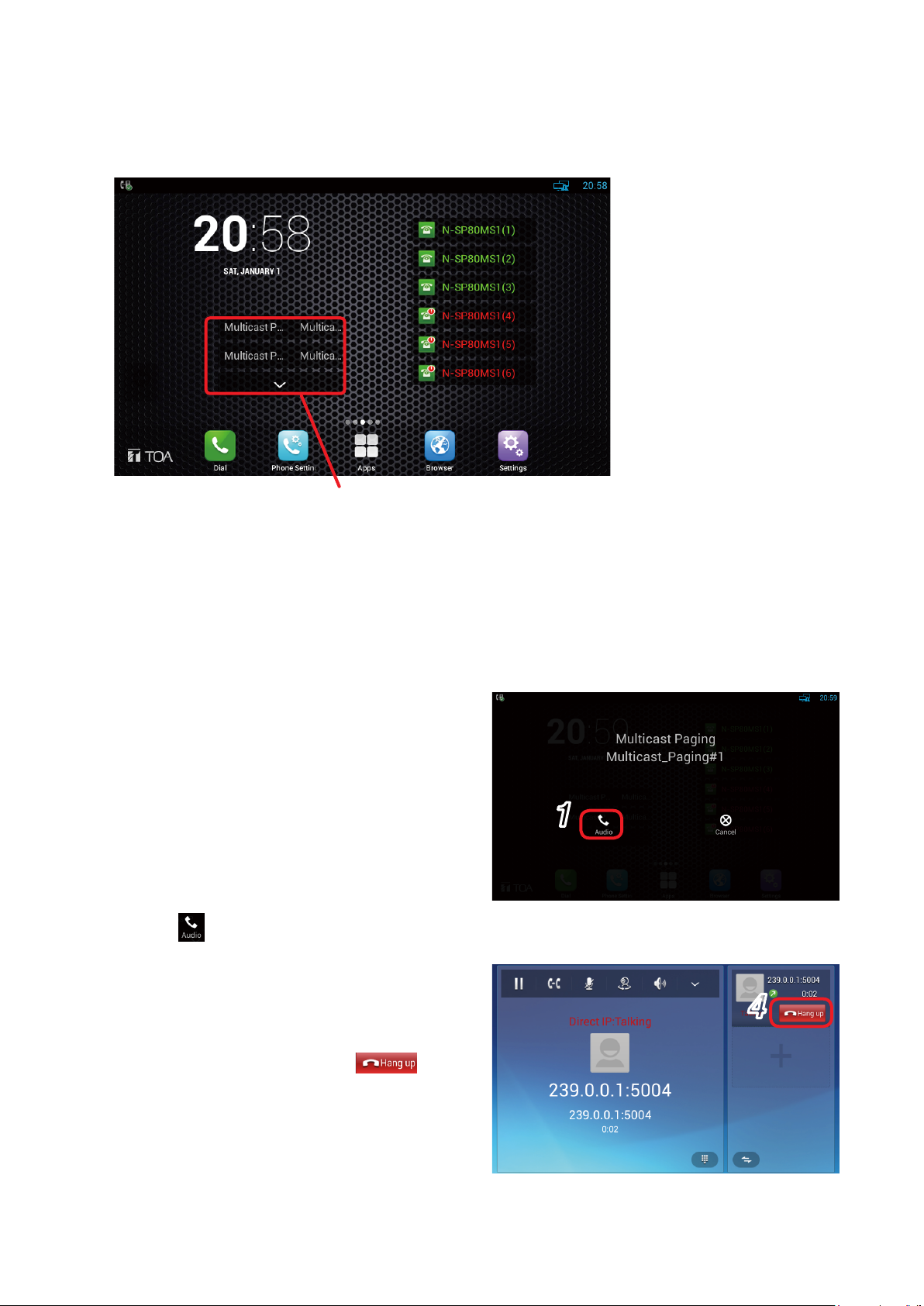
9.3. Paging Call Operation
Paging calls can be made using the Multicast paging function.
Perform paging call operation by clicking the shortcut icon of the Multicast paging.
Shortcut icons of the Multicast paging
Tip
If the shortcut icon of the Multicast paging cannot be viewed on the screen, see p. 46 "Creating the shortcut
of the EXT key."
Step 1. Click the shortcut icon of the Multicast
paging.
A paging call screen appears.
(Paging call screen)
1
Step 2. Click .
A dial screen appears.
(Dial screen)
Step 3. Lift the handset or press the Speaker button
to start paging call.
Step 4. Hang up the handset or touch on
the Dial screen to terminate paging call.
4
23
Page 24

9.4. Other Functions and Operations
9.4.1. 3 party conference
• The multimedia station supports 3 lines of conversations.
• The line information during conversation appears in the windows on the right side
of the conversation screen.
[3 party conference operation]
Shown below is an operation example on the screen when the multimedia station No. 5001 calls the multimedia
station No. 5002 and the video door station No. 5003 to make 3 party video conference among them.
Step 1. Make conversations between 2 parties.
Operation of the conversation between 2 parties is the same as that of the normal call.
Tip
It does not matter whether the conversation is initiated by being called from a door station or another
multimedia station.
Step 2. Touc h or .
A conversation screen appears.
Step 3. Touc h button displayed in the window
on the right side of the conversation screen.
The current conversation is placed on
hold and the entry screen for calling a new
station appears.
Step 4. Enter the station number to join the 3 party
conference on the entry screen, then touch
or .
The conversation screen on which the
added station number is displayed.
2
3
4
4
24
Page 25

Step 5. Touch the 3 party conference icon
displayed on the bar at the top of the
conversation screen.
Tip
If icon is not displayed, touch icon
displayed on the bar at the top.
The screen is switched and the icons of
the station numbers that join the 3 party
conference appears.
Step 6. Touch the icons of the 2 station numbers to
join 3 party conference.
Check marks are put on the clicked icons.
5
6
Step 7. Touc h .
3 party conference starts and the screen
changes to the conversation screen.
The conversation screen of the multimedia
station during 3 party video conference
shows the screen of each station in a
divided display as shown at right.
(A): Camera image of the station added to
the call destination station in Step 4.
(B): Camera image of the own station.
"Local" indication appears at the
upper left corner of the split screen.
(C): Camera image of the partner station
which was engaged in 2 party
conversation in Step 1.
The station number appears at the
upper left corner of the screen.
7
(A)
(B) (C)
Tips
• Touch the screen (C) to switch the image displayed in the screen (C) to that displayed in the screen
(A).
• The screens (A) and (C) are not displayed when the partner station is a door station.
25
Page 26

9.4.2. Connecting to a third-party VoIP
The SIP compliant VoIP station can be generally connected to the N-SP80 Series station.
Basic operations (Call, call reception, hold, and transfer, etc) are the same as those of the N-SP80MS1.
Notes
• As connection compatibility must be ensured, perform connection conrmation in advance.
• Conrm that the audio codec supports the VoIP devices to use.
The audio codec of the N-SP80 series is xed to G.722 when using the station in Peer-to-peer mode.
9.4.3. Connection with outside line (in SIP server mode)
The SIP server needs to have congurations of outside line (Telephone line). When settings and operations
are performed according to the assignment of the special number to the outside line, the station can call the
outside line telephone.
For example, when the special number assigned to the outside line is "0," the outside line telephone can be
called directly provided that the call button on the door station is set to "0-080-****-####."
SIP server
9.4.4. Door remote control
When entering the preset number* assigned to the door station during conversation with it, you can remotely
lock or unlock the door near the station engaged in conversation.
The sound or message which informs that the lock is opened or closed can also be output from the door station.
* The number set in the DTMF of the p. 59 "Intercom - Relay&Input"
Outside line telephone network
26
Page 27

10. DOOR STATION'S FUNCTIONS AND OPERATIONS
10.1 Functions for Conversations and Operations
10.1.1. Making a call
Press the Call button to call up the preset station.
(N-SP80VS1) (N-SP80AS1)
10.1.2. Receiving a call
An incoming call can be received by the automatic response function.
As the call is automatically received, you do not need any operation.
10.1.3. Cancelling a call and conversations
Pressing the Call button during a call or conversations cancels the operation in progress.
10.2. Paging Function
Paging call can be automatically received according to the preset priority level. Any operation is not required
for this function.
27
Page 28

10.3. Other Functions and Operations
10.3.1. No answer forward function
Up to 3 call destinations can be assigned to the Call button. If the rst call destination does not respond, it is
switched to the second call destination. If the second call destination does not respond, it will be switched to
the third call destination.
Set the transfer destination using [Account Selection: No answer call 1 and 2] of "Intercom - Basic" on p. 57.
Call destination
Up to 3 call destinations can be assigned to the
Call button.
No answer
No answer call 1
No answer
No answer call 2
10.3.2. Time limit
Time limit can be set for the call and conversation times.
Set the time limit using [Time Limit: Call time-out and Conversation time-out] of "Intercom - Basic" on p. 57.
R R R R…
Time lapses
If the called station gives no response within the
call time limit, this call is stopped and switched to
the next station call.
Time elapses.
Call time limit
R R R R…
Hello…
Hello…
Time lapses
10.3.3. Door remote control
The door remote control such as opening and closing of the nearby door can be received from the multimedia
station during conversation.
Set the relay output of the door remote control using [Relay] of "Intercom - Relay&Input" on p. 59.
Conversation
time limit
28
Page 29

10.3.4. Call activation from an external device
Door station
The door station can make a call to the station other than those assigned to the Call button when connecting
to an external device or switch.
Note
To perform this call activation, prepare the optional YC-400 4 size back box.
The door station should be installed into the wall using the YC-400. (See p. 30 "Installation of Door station".)
YC-400
Switch device
(Example)
Install a switch device between the door station and the back box in
advance.
Connect the switch device to the external control input so that call
can be executed when the station is removed by a mischief.
10.3.5. Change in various function sounds
You can change or stop the sounds shown below. The sound can be changed by uploading the audio le from
the Web setting screen. (See p. 67.)
• Incoming call sound of the door station
• Call transmission sound
• Door remote control sound
11. INSTALLATION
11.1. Safety Precautions for The Multimedia Station
• Do not install the unit near the heat generating equipment.
• Do not install the unit at the locations which could stand in someone's way or strike someone.
• Never use the unit near the locations where water is handled such as bath room, rest room, and kitchen.
29
Page 30

11.2 Installation of Door Station
(supplied with the door station)
The door station is designed to be mounted into the wall in conjunction with the YC-400 wall recessed 4 size
back box. For mounting, follow the procedure below.
Step 1. Remove a knockout hole in the YC-400.
Before mounting the YC-400 into the wall, punch out the knockout hole with a screwdriver or other tool
to make a cable entry hole.
Step 2. Make a mounting hole in the wall such as a gypsum board, then mount the YC-400 into the wall.
Tip
Install the YC-400 at the appropriate height from the oor (approx. 1.5 m or 5 ft).
[YC-400 dimensional drawing]
[Front] [Side]
98.2 (3.87")
Unit: mm (in)
58.1
(2.29")
Wall
YC-400
Door station
187 (7.36")
[Door station dimensional drawing]
Note
The N-SP80VS1 and the N-SP80AS1 have
the same dimensions.
120 (4.72")
Unit: mm (in)
210 (8.27")
Star head screw M4 x 16
Step 3. Run the connection cable through the cable entry hole in the YC-400, then connect it to the door
station.
Step 4. Secure the door station to the YC-400.
Use the screws supplied with the door station and the star head screwdriver.
30
Page 31

12. CONNECTION
12.1. N-SP80MS1
[Rear]
(2)
(3)
(1)
(5)
Thief-prevention
Supplied handset
(4)
12.1.1. Power supply connection
Power is supplied from the AC adaptor or the PoE-compatible switching hub.
For the power supply from the switching hub, see p. 32 "(2) LAN connection terminal."
(1) DC input terminal
To the switching hub
To a PC
To AC mains
Connect the AC adapter.*
* Use the optional AC adapter AD-1215P or AD-5000-2 (or its equivalent). As for the usable adapter, consult
your TOA dealer.
CAUTION
Tip
If both the AC adapter and the PoE switching hub are connected, the power will be supplied from the one
that has started feeding rst.
The use of the AC adapter other than the specied one may
cause a re.
31
Page 32

12.1.2. Switching hub and PC connections
(2) LAN connection terminal
Connect this terminal to the 100BASE-TX-compatible network.
Use the Ethernet RJ-45 connector for connection.
As this terminal can be connected to PoE switching hub, power can be supplied from the PoE switching hub
when this terminal is connected to it.
In this case, use the switching hub meeting the following specication.
Specication of the usable PoE switching hub: IEEE802.3af compliant
When power is supplied from the PoE switching hub, be sure to
CAUTION
Tip
If both the AC adapter and the PoE switching hub are connected, the power will be supplied from the one
that has started feeding rst.
(3) PC connection terminal
Connect a PC to this terminal.
Use the Ethernet RJ-45 connector for connection.
This terminal can also be connected to the 100BASE-TX-compatible network.
Note
This terminal is not PoE-compatible.
use the one meeting the specied specication.
The use of the switching hub other than the specied one may
cause a re.
12.1.3. Other connections
(4) Handset connection terminal
Connect the supplied handset to this terminal.
(5) Security slot
Connect a commercially available theft preventing wire to this slot as needed.
This is a Kensington lock slot.
12.1.4. USB device connection
(6) USB connection terminal
Connect a USB device such as a USB memory
to this terminal.
This terminal is USB 2.0 compatible.
12.1.5. Headset connection
(7) Connect a headset to this terminal.
Usable headset: 16/32 Ω,
3.5 mm (0.14") dia. mini plug (3 pins)
N-SP80MS1 unit (Right side)
(6)
To a USB device
(USB memory, etc)
(7)
To the headset
32
Page 33

12.2. N-SP80VS1, N-SP80AS1
[Rear]
To control signal
output terminal
To control signal input terminal
(Closed contact)
To control signal input terminal
(Open contact)
To control signal input terminal
(Closed contact)
To control signal input terminal
(Open contact)
External control input
GND
Relay output
COM
COM
12 V
DC power supply
IN2
IN1
NO
NC
NO
NC
2
1
1
2
(1)
(4)
(5)
(2)
(3)
To
switching hub
To
switching hub
12.2.1. Power supply connection
Power is supplied from the 12 V DC power supply or the PoE-compatible switching hub.
For the power supply from the switching hub, see below "(2) Ethernet connection terminal."
(1) DC input terminal
Connect the 12 V DC power supply to this terminal. This terminal has no polarity. Connect the "+" and "–"
cables to each terminal.
Prepare the 12 V DC power supply separately.
Tip
If both the 12 V DC power supply and the PoE switching hub are connected, the power will be supplied from
the one that has started feeding rst.
12.2.2. Switching hub connection
(2) Ethernet connection terminal (PoE compatible)
Connect this terminal to the 100BASE-TX-compatible network.
Use the Ethernet RJ-45 connector for connection.
As this terminal can be connected to PoE switching hub, power can be supplied from the PoE switching hub
when this terminal is connected to it.
In this case, use the switching hub meeting the following specication.
Specication of the usable PoE switching hub: IEEE802.3af compliant
When power is supplied from the PoE switching hub, be sure to
use the one meeting the specied specication.
CAUTION
The use of the switching hub other than the specied one may
cause a re.
Tip
If both the 12 V DC power supply and the PoE switching hub are connected, the power will be supplied from
the one that has started feeding rst.
33
Page 34

(3) Ethernet connection terminal
Connect this terminal to the 100BASE-TX-compatible network.
A PC can also be connected to this terminal when performing various settings.
Use the Ethernet RJ-45 connector for connection.
Note
This terminal is not PoE-compatible.
12.2.3. Other connections
(4) External control input terminal
No-voltage make contact, Open voltage: 30 V DC, Short-circuit current: 10 mA, Short-circuit duration: 200 ms
or more
Connect such a device that outputs the control signals as an external control switch or sensor to this
terminal.
Two channels of the control signals can be applied. The table below shows the combination of the terminals.
Combination of the terminals
Control input 1 IN1 and GND
Control input 2 IN2 and GND
To use these terminals, you need to make the system setting on the browser. For the details, see p. 59.
(5) Relay connection terminals 1 and 2
Contact type: Relay contact output, Contact capacity: 30 V DC, 0.5 A
Connect the device that is controlled by the relay output such as an electric lock to this terminal.
Two channels of the control signals can be output. Also, a closed contact or open contact can be selected
for each signal depending on the terminal to be connected.
The table below shows the combination of the terminals.
Combination of the terminals
When the closed contact is selected When the open contact is selected
Relay output 1 Relay output 1's NO and COM Relay output 1's NC and COM
Relay output 2 Relay output 2's NO and COM Relay output 2's NC and COM
Note
Never connect any devices to both the closed contact and open contact terminals of the same relay output
at the same time, as this could result in the unit failure.
To use these terminals, you need to make the system setting on the browser. For the details, see p. 59.
34
Page 35

13. SYSTEM SETTING USING A WEB BROWSER
13.1. Before Performing System Setting
Access the web servers of all devices using the web browser, then perform settings for each device. Settings
cannot be performed while ofine.
Preparations shown below are required before starting settings.
• MAC address and IP address assignment plan for the devices to use (Phone number assignment plan is also
needed when in SIP server mode.)
• SIP server setting information (when in SIP server mode)
• IP address setting of a PC used in the system setting (Set the IP address so as to belong to the same system
network.)
[Veried browsers (Version)]
· Microsoft Edge (38.14393.1066.0)
· Google Chrome (Version 63.0.3239.132)
· Fire fox (Version 58.0.2)
13.2. Confirming the IP Address of Each Device
13.2.1. N-SP80MS1
Step 1. Touch the Settings icon on the main
screen.
The setting screen opens.
Step 2. Touch the Ethernet item.
The current IP address appears.
2
13.2.2. N-SP80VS1, N-SP80AS1
After turning on the power, perform the operation shown below within the valid time during which the IP address
can be conrmed.
You can set the valid time on the station's web browser setting screen. (See p. 67 "IP Announcement.")
Step: Hold down the Call button for 3 seconds or more.
The IP address of this door station is announced.
It will be announced like "IP one nine two dot, …" in English.
Note
After tuning on the power, if you want to execute this function after the
valid time expires, turn off and on the power again or press the Reset
button on the unit’s rear panel.
Call button
35
Page 36

13.3. N-SP80MS1 Setting
13.3.1. Logging in
Connect to the unit’s Web server by using the IP address.
When the IP address is 192.168.1.101, enter "http://192.168.1.101" to make connection.
For the method to conrm the IP address, see p. 35 "Conrming the IP address of Each Device."
User name and password settings are as follows.
User name: N-SP80
The user name is xed. It cannot be changed.
Password: guest (default setting)
The password can be changed.
Enter it with up to 63 characters.
Notes
• Unusable characters : &, %, ' , =
• Password is case-sensitive.
2
Step 1. Start the PC's browser.
Step 2. Enter the IP address in the address bar.
Tip
The default IP address is 192.168.1.101. (Subnet mask is 255.255.255.0.)
A login screen appears.
Step 3. Enter the user name and password, then click
3
.
36
Page 37

13.3.2. Status - Basic
Item Description
Product Information
Network Information
Account Information
Displays the following product information:
• Model
• Hardware model
• MAC address (Physical address of the IP device)
• Firmware version and Hardware version.
Displays the following network status (LAN port) information of the device:
• LAN port type (one of DHCP static, and PPPoE)
• LAN link status
• LAN IP address
• LAN Subnet Mask
• LAN Gateway
• LAN DNS1
• LAN DNS2
Displays the account information and registration status (account user name,
registered server address, and registration result) of the device.
37
Page 38

13.3.3. Account - Basic
SIP Account
Item Description
Displays or sets the specic account setting.
Status: Displays the registration result.
Account: Select the SIP account to set.
(Select one from Account 1 through 6.)
Account Active: Select Enabled/Disabled of each account.
Display Label: Displayed on the station’s LCD screen.
Display Name: Sent to the called party and displayed.
Register Name: Use the name to be registered (set) in the SIP
server for authentication.
User Name: Use the name to be registered (set) in the SIP
server for authentication.
Password: Use the password to be registered (set) in the SIP
server.
38
Page 39

Item Description
SIP Server 1
SIP Server 2
Outbound Proxy Server*
Displays or sets the Primary SIP server setting.
Server IP: SIP server address that is URL or IP address
Registration Period: An interval to periodically send the registration
(REGISTER) to the SIP server.
Continues to retain the registration in the SIP
server when the station sends registration
(REGISTER) again within the registration
(REGISTER) maintaining period on the SIP
server.
Displays or sets the Secondary SIP server setting.
This is a backup server so that the information communication
station can be registered at the Secondary SIP server even if the
registration to the Primary SIP server fails.
Note
The Secondary SIP server is used as a backup server.
If there is no SIP server for backup in a user environment, these
corresponding elds are left blank.
Displays or sets the Primary SIP server setting.
Server IP: SIP server address that is URL or IP address
Registration Period: An interval to periodically send the registration
(REGISTER) to the SIP server.
Continues to retain the registration in the SIP
server when the station sends registration
(REGISTER) again within the registration
(REGISTER) maintaining period on the SIP
server.
1
Displays or sets the outbound proxy server.
Note
• Once set, all SIP request messages are forcibly sent to the
outbound proxy server from the multimedia station.
• When the external SIP server (such as one for an outside line) is
not used, leave the corresponding elds blank.
Enable Outbound: Sets Enabled/Disabled for the connection to the
outbound server.
Server IP: Sets the IP address to the outbound server to
connect.
Buckup Server IP: Sets the backup server’s IP address if there is a
backup server for the outbound server.
Transport Type
Displays or sets the transfer type of the SIP message.
The type is factory-preset to "UDP."
UDP: An unreliable but highly effective transfer layer protocol.
TCP: A reliable but less effective transfer layer protocol.
NAT
NAT (Network Address Translation): Displays or makes settings.
Stun Server Address*
2
: One of the solutions to solve
NAT problem.
Note
The default NAT is set to Disabled.
1
*
Used to receive all Start request messages and transfer them to the designated SIP server.
*2 Stun stands for Simple Traversal of UDP over NAT.
39
Page 40

13.3.4. Network - Basic
Item Description
LAN Port
* DNS server address
Displays or sets the LAN port setting.
DHCP: Automatically acquires the IP Address, Subnet Mask,
Default Gateway, LAN DNS1*, and LAN DNS2* from the
DHCP server.
Static IP: It is necessary to manually set the IP Address, Subnet
Mask, Default Gateway, LAN DNS1* and LAN DNS2*.
40
Page 41

13.3.5. Phone - Time/Lang
Item Description
Web Language
NTP
Select the language used on the Web setting screen.
Performs the NTP setting for maintaining station’s clock information.
Time Zone: Select a reference time (time zone) to be set to the
device.
Primary Server: Designate the NTP server address to connect to.
41
Page 42

13.3.6. Phone - Preference
Item Description
Key Press Sound
Ringtone Volume
Sets the key operation sound volume.
Volume: Effective volume range is 0 – 15 and the default volume
level is "8."
Sets the ringing tone (call sound) volume.
Volume: Effective volume range is 0 – 15 and the default volume
level is "8."
42
Page 43

13.3.7. Phone - Voice
Item Description
Echo Canceller
Eliminates an acoustic echo from the voice communications to improve the speech
quality.
1
VAD*
(Voice activity detection): Detects presence or absence of the human voice
during conversations using the multimedia station.
"Disabled" is selected by default.
CNG*2 (Comfort noise generation): Generates a comfortable background noise for the
voice communication during the silent period in the
conversation using the multimedia station. This is a
part of the silence suppression or VAD handling of
the VoIP technology.
"Enabled" is selected by default.
Mic Volume
Sets the microphone volume in handset mode.
Handset Volume: Effective volume range is 1 - 10 and the default volume level is "8."
Automatic Gain
Control
The multimedia station automatically adjusts the gain of the amplier circuit via signals.
Automatic Gain Control (Sending-side): "Disabled" is selected by default.
Automatic Gain Control (Receiving-side): "Disabled" is selected by default.
Automatic Gain Control Target: 1 dB – 20 dB, "3 dB" is selected by default.
Net EQ
1
*
When "Silence" period is detected, the VAD efciently replaces it with the special packet showing that
Filter forgetting factor base: 0 – 255, "250" is selected by default.
silence is present. This facilitates the audio processing, disabling some processes to be performed in a
non-audio section during conversation. It is possible to avoid unnecessary coding or transmission of a silent
packet, saving the arithmetic processing and network bands.
2
CNG reacts in conjunction with the VAD algorithm immediately when a silent period occurs, inserting an
*
articial noise in this period until the audio activity resumes.
Inserting an articial noise gives the listeners the illusion that constant transmission stream is present. So,
they do not no t ic e th at the li ne has be en op e ned as the am b ient so und co nti n u es to exi s t duri n g con v e r sat i ons .
43
Page 44

13.3.8. Phone - Video
Item Description
Media Feedback
NACK: "Enabled" is selected by default.
Tmmbr: Sends the temporarily maximum media bit rate request. "Disabled" is
selected by default.
H.264*
1
Settings
Sets the video parameters related to H.264.
H264 Prole: 4 modes are available: Base Prole, Main Prole, High Prole,
and Extend Prole modes. Each different prole makes up a
different coding function and video quality.
H264 Level: A different prole has the corresponding level value.
2
IDR*
Interval: Used to control both coding and decoding processes.
Rate Control: Select the H.264 video bit rate.
Others
Hardware Encode Acceleration: Enables the hardware encoder enhancement
when needed.
"Enabled" is selected by default.
Hardware Decode Acceleration: "Enabled" is selected by default.
Color Enhancement: Improves the multimedia station's display color.
"Enabled" is selected by default.
Image Quality: Select "High," "Middle," or "Low."
"High" is selected by default.
Camera Priority: "Internal" is selected by default.
1
*
A video stream compression standard. The video stream quality is nearly the same as that of H.263, but the
bit rate of H.264 is half that of H.263. This type of compression is sometimes referred to as MPEG-4 part 10.
2
Stands for Instantaneous Decoding Refresh.
*
44
Page 45

13.3.9. Phone - Ext Key
To use the function assigned to the EXT key, it is necessary to create the shortcut of the function-assigned EXT
key you want to use on the multimedia station's main screen.
For the method to create the shortcut of the EXT key, see p. 46.
Current Page
Key
Item Description
4 pages of extension numbers are provided for the multimedia
station.
20 extension number keys are provided on each page.
A specic function can be assigned to each key.
List of the functions assignable to each key is as follows;
• Pickup
• Group Pickup
• Intercom
• History
• Redial
• ACD
• BLF
• BLF List
• Call Return
• Hot desking
• Record
• DTMF
• Multicast Paging
45
Page 46

[Creating the shortcut of the EXT key]
Step 1. Touc h in the lower part of the main screen.
An application list screen appears.
Step 2. Touc h in the upper part of the application list
screen.
A widget screen appears.
Step 3. Swipe the displayed widget screen left until
icon of the EXT key appears.
Step 4. If appears, hold it down for 1 second or more.
The icon becomes slightly larger, and you can move it.
(Lower part of the main screen)
1
(Upper part of the application list screen)
2
(Widget screen)
Swipe
3
4
Press and hold
Step 5. Drag to the shortcut area of the main screen,
then drop it at the desired location.
A selection screen for the EXT key’s shortcut you want
to display appears.
Step 6. Check the checkbox for the EXT key of which function
you want to display on the main screen.
The shortcut icon is created and arranged on the main
screen.
(Main screen).
5
(Shortcut selection screen)
6
46
Page 47

13.3.10. Phone - Dial Plan
Settings and edits of "Replace Rule" and "Dial Now" can be performed by switching the screen.
• Replace Rule: An abbreviated number can be set for the phone number or IP address. (Shown below.)
• Dial Now: Makes the settings of the phone number that can directly call the other party only by dialing without
performing conversation start operation*
*1 An operation to start conversations by pressing the station’s Speaker button (p. 7 ) or touching
or on the screen.
[Replace Rule]
1
. (See. p. 48.)
Item Description
Rule
Area Code*
*2 NPAs (stands for Numbering Plan Areas).
2
Displays or edits "Replace Rule" or "Dial Now" by selecting either one.
Click "Add" to register the rule or "Edit" to edit the registered rule.
• Account: Sets the account to use. "Auto" is selected by default.
• Prex: Sets the abbreviated number to be assigned to the phone number or IP
address.
• Replace: Sets the phone number or IP address to which abbreviated number is
assigned.
Shows the geographical areas in the country.
The multimedia station automatically gives the area code before the call number when
the entered number matches the predened area code rule.
Note
Only one area code is supported.
47
Page 48

[Dial Now]
Item Description
Rule
Area Code*
* NPAs (stands for Numbering Plan Areas).
Displays or edits "Replace Rule" or "Dial Now" by selecting either one.
Click "Add" to register the rule or "Edit" to edit the registered rule.
• Account: Sets the account to use. "Auto" is selected by default.
• Dial Now Rule: Sets the existing phone number that you can directly call.
Shows the geographical areas in the country.
The multimedia station automatically gives the area code before the call number when
the entered number matches the predened area code rule.
Note
Only one area code is supported.
48
Page 49

13.3.11. Phone Book - Local Book
49
Page 50

Contact
Search
Dial
Contact Setting
Group
Group Setting
Import/Export
Item Description
All Contacts: Displays or edits all local contacts.
Favorites: Displays or edits the frequently used contact.
Black List: Not used.
Searches the designated contact from the local phone book.
Not used.
Click "Add" when registering the contact setting such as Name,
Ofce Num, Mobile Num, Other Num, and Group, and click "Edit"
when editing the registered contact setting.
Displays or deletes the group.
Displays or registers the group name and description.
Click "Add" when registering the group and click "Edit" when editing
the registered rule.
Imports or exports the Contact ("All Contacts" and "Favorites") in the
form of an XML le or a CSV le.
50
Page 51

13.3.12. PhoneBook - Call Log
Item Description
Call History
* All outgoing and incoming calls
Displays the call history.
Type of display can be selected from those listed below.
• All*
• Dialed
• Received
• Missed
• Forwarded
51
Page 52

13.3.13. Upgrade - Basic
Item Description
Firmware Version
Hardware Version
Upgrade
Reset To Factory Setting
Reset Cong to Factory Setting
Reboot
Displays the rmware version.
Displays the hardware version.
Select the le to be automatically upgraded from the local or remote
server.
Note
Conrm that the le format is appropriate for that device.
Example of a le: r47p-47.192.7.662-toa.zip
Returns the IP address and account information to the initial value.
• IP address: 192.168.1.101
• Account information: Blank
Resets the Cong le (setting le) to factory default.
The IP address and account information remain unchanged.
Click "Submit" to reboot the device.
52
Page 53

13.3.14. Upgrade - Advanced
Item Description
PCAP
Others
Starts or stops the packet capturing. Exports the captured packets le as well.
Start: Starts capturing all the packet les received by or sent from the
multimedia station.
Stop: Stops the packet capturing.
Export: Captures the saved packet le.
PCAP Auto Refresh: When "Enabled" is selected for automatic update, the packet data
is constantly overwritten.
Note
The multimedia station saves the captured packets les into the temporary le.
The maximum size of this le is 1 MB. When the saved data reaches this limit, the
station stops capturing data.
Exports or imports the setting le of the multimedia station.
Setting les in .tgz/.conf/.cfg format can be handled.
Export: Encrypts and downloads the setting le. This le is downloaded in .tgz format.
Import: Uploads the le set in the Cong le to the device, updating the device settings.
53
Page 54

13.3.15. Security - Basic
Item Description
Web Password Modify
Session Time Out
Changes the user password.
User Name: N-SP80
The user name is xed. It cannot be changed.
Current Password: guest (default setting)
The password can be changed.
New Password: Enter it with up to 63 characters.
Note
• Unusable characters : &, %, ' , =
• Password is case-sensitive.
Conrm Password: Enter the new password again.
Note
Set the security through the Web only.
Session Time Out Value: Limits the log-in time.
When the log-in time exceeds the set time limit,
you need to re-login to the Web site.
"300" is selected by default.
54
Page 55

13.4. N-SP80VS1 and N-SP80AS1 Settings
13.4.1. Logging in
Connect to the unit's Web server by using the IP address.
When the IP address is 192.168.1.102, enter "http://192.168.1.102" to make connection.
For the method to conrm the IP address, see p. 35 "Conrming the IP address of Each Device."
User name and password settings are as follows.
User name: N-SP80
The user name is xed. It cannot be changed.
Password: guest (default setting)
The password can be changed.
Enter it with up to 63 characters.
Notes
• Unusable characters : &, %, ‘ , =
• Password is case-sensitive.
2
Step 1. Start the PC's browser.
Step 2. Enter the IP address in the address bar.
Tip
The default IP address is 192.168.1.102. (Subnet mask is 255.255.255.0.)
A login screen appears.
Step 3. Enter the user name and password, then click
3
.
55
Page 56

13.4.2. Status - Basic
Item Description
Product Information
Network Information
Account Information
Displays the following product information:
• Model
• MAC address (Physical address of the IP device)
• Firmware version and Hardware version.
Displays the following network status (LAN port) information of the device:
• LAN port type
• LAN link status
• LAN IP address
• LAN Subnet Mask
• LAN Gateway
• LAN DNS1
• LAN DNS2
Displays the account information and registration status (account user name,
registered server address, and registration result) of the device.
56
Page 57

13.4.3. Intercom - Basic
Item Description
Account Selection
Push Button
Web Call
Time Limit
Push To Hang Up
* A function that can "Hang up" the call by pressing the Call button again while the door station is making a call
or engaged in conversation.
Select Account: The door station supports 2 accounts.
You can select a single account or Automatic mode with
the Intercom basic settings below.
"Auto" is selected by default.
No Answer Call: Transfers the call to another station when the called party
does not answer.
"Disabled" is selected by default.
Push Button: Up to 3 call destinations can be set.
If the main call destination station does not answer for the
given period, the call to that station stops and moves to the
next station assigned to No answer call destination 1. Up to 2
No answer destinations can be set.
"Disabled" is selected by default.
Remotely calls the station number entered in this eld from the multimedia
station connected to this screen.
Sets the maximum call time-out and conversation time-out durations.
Call time-out: "60" seconds is set by default.
Conversation time-out: "120" seconds is set by default.
Sets "Push to Hang Up" function* to "Enabled" or "Disabled."
"Enabled" is selected by default.
57
Page 58

13.4.4. Intercom - LED Setting
Item Description
LED Setting
* Each setting value shows the ashing interval as Lit duration/Unlit duration (msec).
The table below shows the LED’s initial settings.
State
NORMAL
OFFLINE
CALLING
TALKING
RECEIVING
State: Designates the door station's state to decide the LED’s lighting pattern.
State Description of state
NORMAL
OFFLINE
CALLING
TALKING
RECEIVING
Color Off: (Not used)
Color On: Sets color while ashing or lit.
Select red, blue, green, or Off.
Blink Mode: Sets Lit, Unlit, and Flashing patterns
Lit: "Always On"
(msec)
Unlit: "Always Off"
Flashing*
Color Off Color On Blink Mode
OFF Blue Always On
OFF Red 2500/2500
OFF Blue 2500/2500
OFF Green Always On
OFF Green 2500/2500
: "500/500", "1000/1000", "2500/2500", "3000/3000"
Standby
Connection to Network and SIP not established
Calling in progress
Conversation in progress
Receiving an incoming call
58
Page 59

13.4.5. Intercom - Relay&Input
Item Description
Relay
Input
Performs the settings related to the door lock release when the door remote control
function is used.
Relay ID: The door station has 2 relay control outputs.
Relay Type: Each lock is controlled using a different relay type.
Relay Delay(sec): Leaves the door open for the given period of time. The time range is 1 to
5 seconds.
DTMF: Sets the DTMF code with which the lock release is remotely controlled.
Relay Status: Displays each relay type status.
Connects to the external control switch.
Example of use:
Install a sensor switch functioned as a vandal prevention device between the door station
and the back box. Connect the sensor’s output to the door station’s input.
If the door station is destroyed violently, the sensor is activated and outputs an alarm
signal.
Note
The door station has no sensor function.
Input ID: The door station has 2 built-in photo couplers on the inputs. If the photo
coupler operates, an alarm signal is output when this function is set to
"Enabled."
Input Service: "Disabled" is selected by default.
Call Number: Sets the call number of the alarm control center.
Display Name: The calling party’s name is sent to and displayed on the called station.
Call Timer: Continues a call for the set time while the input is being activated.
Light Status: Displays the input status.
59
Page 60

13.4.6. Intercom - Live Stream
Item Description
Live Stream
13.4.7. Intercom - AEC Setting
Allows to monitor the real-time images from the N-SP80VS1.
Item Description
AEC Setting
AEC (Acoustic Echo Canceller) is used to adjust an echo effect during conversation.
"700" is set by default.
The higher the level is, the more the echo is suppressed. (The station is placed in
half-duplex conversation state.)
60
Page 61

13.4.8. Intercom - RTSP
Item Description
RTSP Basic
RTSP Stream
Activating the RTSP function allows the N-SP80VS1 to monitor.
To enable the RTSP video, select the video codec.
The N-SP80VS1 supports H.264 and H.263 video codec.
"H.264" is selected by default.
H.264*
MPEG4*
MJPEG*
1
*
1
Video Parameters
2
Video Parameters
3
Video Parameters
A video stream compression standard. The video stream quality is nearly the same as that of H.263, but the
Changes the resolution, frame rate, and bit rate of H.264 parameter.
Changes the resolution, frame rate, and bit rate of MPEG4.
Changes the resolution, frame rate, and bit rate of MJPEG.
bit rate of H.264 is half that of H.263. This type of compression is sometimes referred to as MPEG-4 part 10.
*2 One of the network video image compression standards
*3 MJPEG stands for Motion Joint Photographic Experts Group. A video encoding format where each frame is
individually compressed by JPEG.
High quality video images are generated with the MJPEG compression, enabling the video resolution and
compression frame to be set exibly.
61
Page 62

13.4.9. Intercom - ONVIF
Item Description
Basic Setting
Sets the ONVIF function parameters. Use this function to connect the station to the
corresponding ONVIF tool.
ONVIF Mode: Sets Discoverable or Non-discoverable function mode.
"Discoverable" is selected by default. The N-SP80VS1 can be detected
only in Discoverable mode using the ONVIF software.
User Name: Change the user name as needed. "N-SP80" is set by default.
Password: Change to the desired password. "guest" is set by default.
Enter with up to 63 characters.
Note
Symbols below and 2-byte characters cannot be used.
& % ' =
62
Page 63

13.4.10. Account - Basic
Item Description
SIP Account
SIP Server 1
Displays or sets the specic account.
Status: Displays the registration result.
Account: Selects the account to set. (Account 1 or Account 2)
Account Active: Validates the selected account.
Display Label: A station name that is recorded in log.
Display Name: Sent to the called party and displayed.
Register Name: Use the name to be registered (set) in the SIP server for authentication.
User Name: Use the name to be registered (set) in the SIP server for authentication.
Password: Use the password to be registered (set) in the SIP server.
Displays or sets the Primary SIP server settings.
Server IP: SIP server address that is URL or IP address
Registration Period: An interval to periodically send the registration (REGISTER) to the
SIP server.
Continues to retain the registration in the SIP server when the
station sends registration (REGISTER) again within the registration
(REGISTER) maintaining period on the SIP server.
63
Page 64

Item Description
SIP Server 2
Displays or sets the Secondary SIP server setting.
This is a backup server so that the IP station can be registered at the Secondary SIP
server even if the registration to the Primary SIP server fails.
Note
The Secondary SIP server is used as a backup server. If there is no SIP server for
backup in a user environment, these corresponding elds are left blank.
Outbound Proxy
Server*
1
Enable Outbound: Sets Enabled/Disabled for the connection to the outbound server.
Server IP: Sets the IP address of the outbound server to connect.
Backup Server IP: Sets the backup server’s IP address if there is a backup server for
the outbound server.
Transport Type
Selects the SIP message's transfer type from a pull-down menu.
UDP: An unreliable but highly effective transfer layer protocol.
TCP: A reliable but less effective transfer layer protocol.
TLS: A safe and reliable transfer layer protocol.
DNS-SRV: DNS RR to designate the server location.
NAT
Displays or sets the NAT (Network Address Translator) settings.
Stun Server Address*
2
: One of the solutions to solve NAT problem.
Note
"Disabled" is selected for NAT by default.
1
*
Used to receive all Start request messages and transfer them to the designated SIP server.
*2 Stun stands for Simple Traversal of UDP over NAT.
64
Page 65

13.4.11. Network - Basic
Item Description
LAN Port
Displays or sets LAN port setting.
DHCP: Automatically acquires the IP address, Subnet Mask, Default gateway, and DNS
server address from the DHCP server.
Static IP: It is necessary to manually set the IP address, Subnet Mask, Default gateway,
and DNS server address.
65
Page 66

13.4.12. Phone - Time/Lang
Item Description
Web Language
NTP
Selects language used on the Web setting screen.
Performs the NTP (Network Time Protocol) server related settings.
Time Zone: Selects the local time zone for the NTP server.
Primary Server: Sets the Primary NTP server address.
Secondary Server: Sets the Secondary NTP server address. Becomes accessible
when the Primary NTP server cannot be accessed.
Update interval: Sets the interval between 2 consecutive NTP requests.
System Time: Clock of the currently connected device.
Note
NTP is used to automatically synchronize the local time with the internet time.
As the NTP server supports only the GMT time, it is necessary to specify the time zone
in order to set station's local time.
66
Page 67

13.4.13. Phone - Voice
Item Description
Mic Volume
Speaker Volume
IP Announcement
Open Door Warning
Ring Tone
Opendoor Tone Upload
RingBack Upload
CallTone Upload
* The IP address will be announced from the station's speaker if you hold down the door station's Call button
for 5 seconds or more.
Sets the microphone's volume level.
Sets the speaker's volume level.
Performs the settings about the voice announcement* of IP address.
Becomes active within the preset period (second) from power-on.
Sets the door remote's control sound.
Select "Disabled" if you do not want to listen to the voice alarm message when
the door lock is opened.
RingBack: "Enabled" is selected by default.
CallTone: "Enabled" is selected by default.
Uploads the sound when the door remote control function operates.
Uploads the ring tone that sounds when the door station's Call button is pressed.
Uploads the call tone that sounds when the door station receives an incoming
call from the other device.
67
Page 68

13.4.14. Phone - Multicast
Item Description
Multicast Setting
Priority List
Displays or sets the Multicast setting.
Paging Barge: Enables or disables the priority level between a call and a paging
call.
1 (Enabled): The priority level of the paging call is higher than
that of the call.
Disabled: The priority level of the paging call is lower than
that of the call.
Sets the Multicast parameters.
Listening Address: Enter IP address from which you want to listen to the paging.
Label: Enter the label of each listening address.
68
Page 69

13.4.15. Upgrade - Basic
Item Description
Firmware Version
Hardware Version
Upgrade
Reset to Factory Setting
Reboot
Displays the rmware version.
Displays the hardware version.
Automatically selects the ROM le for upgrade from the local or remote
server.
Note
Check if the le format is correct for that model.
Example of the le name: 21.192.2.33.rom
Returns the IP address and account information to the initial value.
• IP address: 192.168.1.102
• Account information: Blank
Remotely restarts the currently connected station.
69
Page 70

13.4.15. Upgrade - Advanced
Item Description
PCAP Starts or stops packet capturing. Exports the captured packets le as well.
Start: Starts capturing all the packet les sent to and received from the IP
telephone.
Stop: Stops the packet capturing.
Export: Exports the capturing packets les.
PCAP Auto Refresh: When "Enabled" is selected for automatic update, the packet data is
constantly overwritten.
"Disabled" is selected by default.
Note
The IP telephone saves the captured packets le into the temporary le. The maximum size
of this le is 1 MB. When the saved data reaches this limit, the station stops capturing packets
le.
Others Cong le: Exports or imports the IP telephone's setting les.
70
Page 71

13.4.16. Security - Basic
Item Description
Web Password Modify Changes the user password.
Current password: Enter the currently used password.
New password: Enter the new password you want to use.
Enter with up to 63 characters.
Note
Symbols below and 2-byte characters cannot be used.
Conrm password: Enter the new password again.
Note
Currently, the IP telephone supports only user "N-SP80."
71
Page 72

14. TROUBLE SHOOTING
Symptom Remedy
The station can neither
make a call nor receive
an incoming call.
Reboot the station or turn off and on the power.
• In the case of the multimedia station, reboot it.
• In the case of the door station, turn off and on the power.
Conrm the settings shown below according to the set
mode.
• When in Peer-to-peer mode
Conrm the IP address setting. If it has returned to the
initial value, reset it.
[IP address's initial value]
· Multimedia station: 192.168.1.101
· Door station: 192.168.1.102
• When in SIP server mode
Conrm the SIP account's basic settings. If the
displayed name and registered name have returned to
the initial settings, reset them.
[Displayed name's initial setting]
· Multimedia station: No name assigned (Blank)
· Door station: No name assigned (Blank)
Reference page
Operation Setting
p. 7
p. 9
p. 35
p. 35
p. 40
p. 65
p. 38
p. 63
[Registered name's initial setting]
· Multimedia station: No name assigned (Blank)
· Door station: No name assigned (Blank)
p. 38
p. 63
72
Page 73

15. SPECIFICATION
15.1. N-SP80MS1 SIP Multimedia Station
Power Supply
Power Consumption
Speech Method
Audio Bandwidth
Hands-free
Handset
Headset
Display
Camera
Video
Network
External Interface
Installation Method
Operating Temperature
Operating Humidity
Finish
Dimensions
Weight
PoE (IEEE802.3af) or 12 V DC (use of the optional AC adapter)
12 W or less
Hands-free or Handset or Headset conversation
G.722 codec: up to 7 kHz
Speaker: 5 cm (1.97") Cone-type, Maximum output 2 W, 8 Ω
Microphone: Omni-directional electret condenser microphone
Receive path: 3.6 cm (1.42") Cone-type, Maximum output 30 mW, 32 Ω
Send path: Electret condenser microphone
Speaker: 20 mW, 16 Ω/32 Ω, ø3.5 mini jack (3P)
7 inch capacitive touch screen TFT LCD, 800 x 480 pixels, 16:9 wide screen
Image device: 1/5" CMOS
Number of effective pixels: 2 M pixels
Maximum resolution: 1080 p
Other features: Free-Rotation
Image size: QCIF, QVGA, CIF, 4CIF, VGA
Bit rate: 64 kbps − 2 Mbps
Network I/F: 10BASE-T/100BASE-TX (Auto-Negotiation)
Network protocol: UDP/TCP/IP, RTP/RTCP, ARP/RARP, NAT, NTP,
IGMP, SIP, etc.
Packet transmission system: Unicast, Multicast
Paging: Multicast transmission x 1
Connector: RJ45, 2 ports (one supports PoE (IEEE802.3af))
Quantifying bit number: Maximum 16 bits
Voice encoding method: G.711 µ-law/A-law, G.722, G.729
Video compression method: H.263, H.264
USB 2.0
Desktop
0 °C to 40 °C (32 °F to 104 °F)
10 % to 90 %RH (no condensation)
Body, Handset: ABS resin, black
240 (w) x 214 (h) x 117 (d) mm or 9.45" x 8.4 3" x 4.61" (excl udin g a cur l cord section)*
1.1 kg (2.43 lb)
* Numerical values are for reference only.
Note: The design and specications are subject to change without notice for improvement.
• Accessories
Handset ..................................................... 1
Carl cord .................................................... 1
LAN cable .................................................. 1
• Optional products
AC adaptor: AD-1215P, AD-5000-2
73
Page 74

15.2. N-SP80VS1 SIP Video Door Station
Power Supply PoE (IEEE802.3af) or 12 V DC
Power Consumption 12 W or less
Speech Method Hands-free conversation
Audio Bandwidth G.722 codec: up to 7 kHz
Hands-Free Speaker: 5 cm (1.97") Cone-type, Maximum output 1 W, 8 Ω
Microphone: Omni-directional electret condenser microphone
Control Input 2 channels, no-voltage make contact input, open circuit voltage: 5 V DC,
short-circuit current: 10 mA or less
Control Output 2 channels, relay output, normal open/normal close output,
withstand voltage: 30 V DC, control current: 1 A
DC Power Input 12 V DC
Operation Button Call button x 1, Reset button x 1
Indication Status LED
Camera Image device: 1/3" CMOS
Number of effective pixels: 3 M pixels
Maximum resolution: 1080 p
Angle of View: (Horizontal) 120°, (Vertical) 64°
IR light: IR LED
Day & night mode: Color camera (day-mode)/black & white camera
(night-mode), Automatic switching
Network Network I/F: 10BASE-T/100BASE-TX (Auto-Negotiation)
Network Protocol: IPv4, HTTP, HTTPS, FTP, SNMP, DNS, NTP,
RTSP, RTP, TCP, UDP, ICMP, DHCP, ARP, SIP
Packet transmission system: Unicast, Multicast
Paging: Multicast receive x 1
Connector: RJ45, 2 ports (one supports PoE (IEEE802.3af))
Quantifying bit number: Maximum 16 bits
Voice encoding method: G.711 µ-law/A-law, G.722, G.729
Video compression method: H.264, MPEG-4, MJPEG
Security: Password protection, IP address ltering, SIP
over TLS, HTTPS
Speech Features SIP: SIPv1 (RFC2543), SIPv2 (RFC3261)
Audio features: Acoustic echo canceller, VAD (Voice Activity Detection),
Comfort noise generator
Others: Auto answer, Volume control, Peer-to-peer connection (Direct
IP connection without SIP server)
Installation Method Flush-mount
Operating Temperature −20 °C to +55 °C (−4 °F to 131 °F)
Operating Humidity 10 to 90 %RH (no condensation)
Dust/Water Protection IP65 (Panel)
Finish Panel: Stainless steel
Dimensions 120 (w) x 210 (h) x 49.5 (d) mm (4.72" x 8.27" x 1.95")
Weight 910 g (2.01 lb)
Applicable Box 4 size back box: YC-400
Note: The design and specications are subject to change without notice for improvement.
• Accessories
Star head screw M4 x 16 for box mounting .... 4
Star head screwdriver .................................... 1
74
Page 75

15.3. N-SP80AS1 SIP Audio Door Station
Power Supply PoE (IEEE802.3af) or 12 V DC
Power Consumption 12 W or less
Speech Method Hands-free conversation
Audio Bandwidth G.722 codec: up to 7 kHz
Hands-Free Speaker: 5 cm (1.97") Cone-type, Maximum output 1 W, 8 Ω
Microphone: Omni-directional electret condenser microphone
Control Input 2 channels, no-voltage make contact input, open circuit voltage: 5 V DC, short-
circuit current: 10 mA or less
Control Output 2 channels, relay output, normal open/normal close output, withstand voltage:
30 V DC, control current: 1 A
DC Power Input 12 V DC
Operation Button Call button x 1, Reset button x 1
Indication Status LED
Network Network I/F: 10BASE-T/100BASE-TX (Auto-Negotiation)
Network Protocol: IPv4, HTTP, HTTPS, FTP, SNMP, DNS, NTP,
RTSP, RTP, TCP, UDP, ICMP, DHCP, ARP, SIP
Packet transmission system: Unicast, Multicast
Paging: Multicast receive x 1
Connector: RJ45, 2 ports (one supports PoE (IEEE802.3af))
Quantifying bit number: Maximum 16 bits
Voice encoding method: G.711 µ-law/A-law, G.722, G.729
Security: Password protection, IP address ltering, SIP
over TLS, HTTPS
Speech Features SIP: SIPv1 (RFC2543), SIPv2 (RFC3261)
Audio features: Acoustic echo canceller, VAD (Voice Activity Detection),
Comfort noise generator
Others: Auto answer, Volume control, Peer-to-peer connection (Direct
IP connection without SIP server)
Installation Method Flush-mount
Operating Temperature −20 °C to +55 °C (−4 °F to 131 °F)
Operating Humidity 10 % to 90 %RH (no condensation)
Dust/Water Protection IP65 (Panel)
Finish Panel: Stainless steel
Dimensions 120 (w) x 210 (h) x 49.5 (d) mm (4.72" x 8.27" x 1.95")
Weight 870 g (1.92 lb)
Applicable Box 4 size back box: YC-400
Note: The design and specications are subject to change without notice for improvement.
• Accessories
Star head screw M4 x 16 for box mounting .... 4
Star head screwdriver .................................... 1
75
Page 76

15.4. YC-400 4 Size Back Box
Finish Surface-treated steel plate, silver
Dimensions 98.2 (w) x 187 (h) x 58.1 (d) mm (3.87" x 7.36" x 2.29")
Weight 450 g (0.99 lb)
URL: https://www.toa.jp/
201812
 Loading...