

Toa WT-740U Operation Instructions Manual
WIRELESS TUNER
Operation Instructions
WT-740U
The WT-740U wireless tuner has been manufactured for use with a VHF high band
system. When equipped with the WTU-740U tuner module (optional), it permits
reception of up t o t w o different frequency channels.
CAUTION
RISK
OF
FIRE
OR
ELECTRIC
SHOCK. UNIT
NOT
INTENDED
FOR USE
WITH
EXTERNAL ANTENNA.
Part Names And Functions
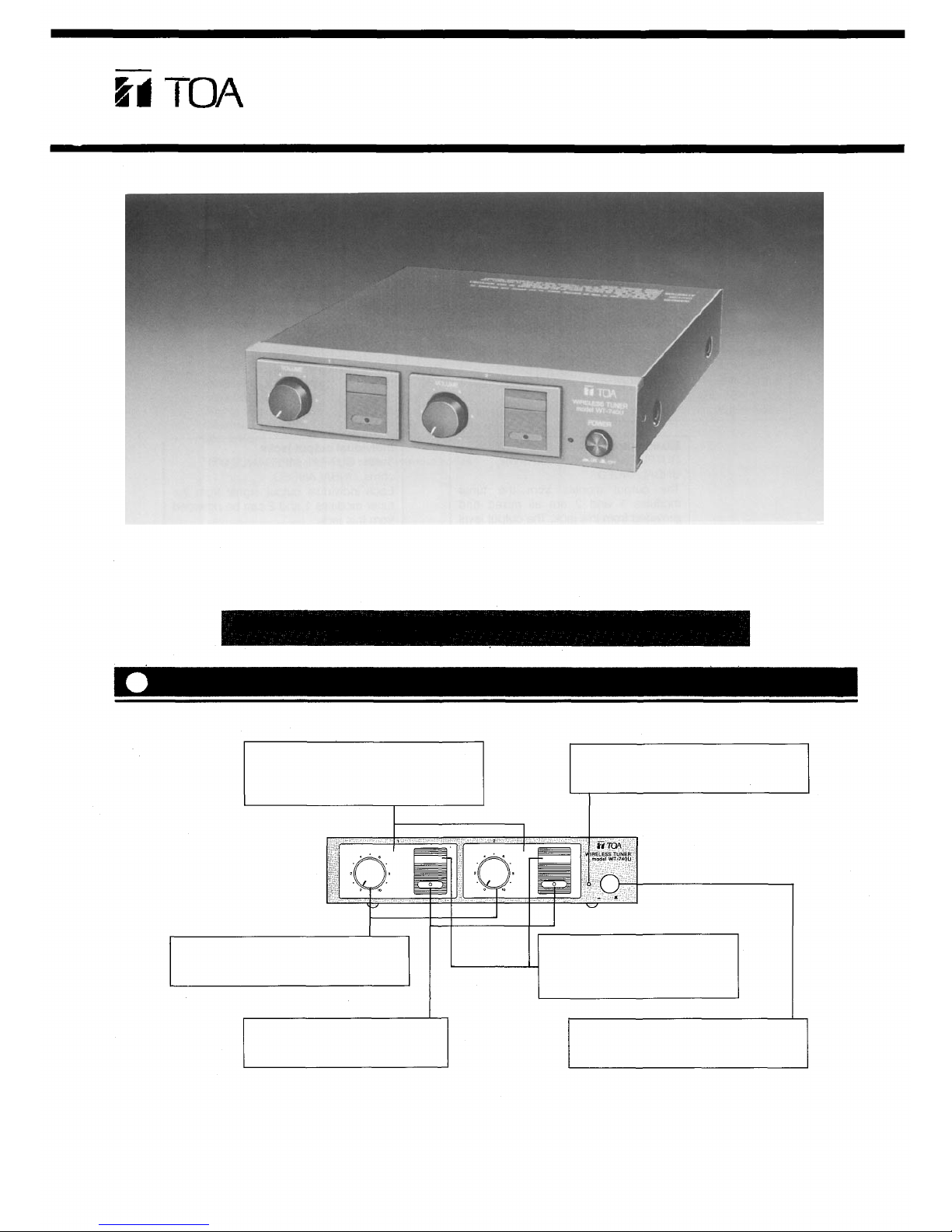
Front panel
Tuner module port
The WTU-740U tuner module (optional)
is inserted into this port by a qualified
service personnel.
Power indicator lamp
The lamp is illuminated when turning
power on.
Volume control (VOL1 and 2)
These volume controls adjust th e sound
volume of the wireless microphones.
Reception indicator
The indicator comes on when the
antenna receives a signal.
Frequency label
Attach here the frequency label
supplied with the WTU-740U
wireless tuner module (optional).
Power ON-OFF switch
Press the swi tch to turn power on. To
turn power off, press the switch again.
Part Names A nd Functions
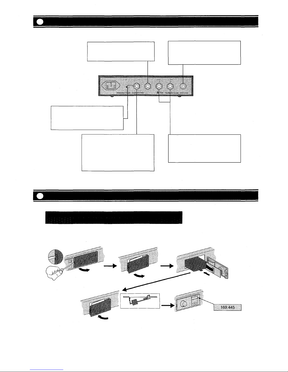
Rear panel
Mixing input jack
Connects this jack to the 0 dBv, 600
ohms, unbalanced output jack of
another WT-740U.
Antenna input connector
(BNC, 75 ohms)
Connects to an optional dipole antenna
"YW-450U" or an optional w hip antenna
"YW-460U"
Mixed output level selector
This switch changes over the mixing
output level.
MIC : -65 dBv
LINE: 0 dB v
Mixed output jack
OUTPUT IMPEDANCE 600 ohms,
UNBALANCED.
The output signals from the tuner
modules 1 and 2 are all mixed and
provided from this jack. The output level
can be selected with the mixing output
level selector.
Individual output jacks
0 dBv, OUTPUT IMPEDANCE 600
ohms, UNBALANCED.
Each individual output signal from the
tuner modules 1 and 2 can be provided
from this jack.
Mounting The WTU-740U Tuner Module
CAUTION: The setting of the tuner module WTU-740U has to be
done by a qualified ser vic e personnel.
1. Press the stopper of the tuner
panel with a screw driver.
3. Open the tuner panel.
4. Insert a tuner module.
2. Pull the tuner panel towards
you while pressing the stopper.
5. After checking to confirm the
tight connection of the tuner
panel connector, fit the tuner
panel in place.
6. Attach the frequency label
supplied with the tuner module
to the assigned space.
 Loading...