

Page 1
OPERATING INSTRUCTIONS
PROGRAM TIMER
TT-104B
WARNING : (For U.S.A. only)
This equipment generates, uses, and can radiate radio frequency energy and if
not installed and used in accordance with the operating instructions, may cause
interference to radio communications. It has been tested and found to comply
with the limits for a Class A computing device pursuant to Subpart J of Part 15
of FCC Rules, which are designed to provide reasonable protection against
such interference when operated in a commercial environment.
Operation of this equipment in a residential area is likely to cause interference in
which case the user at his own expense will be required to take whatever
measures may be required to correct the interference.
FEATURES
The TT-104B is a program timer having 4 independent output channels.
Weekly program capacity is 30 steps per channel, and each step can be programed in an increment of 1
minute.
A channel assignment switch turns B, C and D outputs into A output.
Programing, its change or cancellation can be performed easily and precisely through individual key
operation and display.
Setting the pause mode allows no program output to be delivered.
Output is a no-voltage make contact that connects for five seconds at the programed time.
Built-in buzzer audibly warns the user of key operation error.
Monthly error is ± 5 seconds at 25 °C of ambient temperature.
Clock and stored programs can be maintained for approximately 100 hours in the event of power outage.
INSTALLATION PRECAUTION
Do not switch power on and off frequently because this can shorten the power-outage backup time.
Be sure to set the memory backup switch to ON after installation.
Do not install unit close to a warm air vent or in locations where the unit is exposed to the sunlight.
Installation in high temperature areas like on the amplifier makes a clock inaccurate. Install the unit in the
area of which temperature is as close as possible to the room temperature.
Install the unit as far as possible from a radio tuner or a wireless microphone.
Be sure to ground the unit.
Be sure to unplug power cord from the wall outlet when making connections.
TOA Corporation
Page 2

CONTENTS
FEATURES
INSTALLATION PRECAUTION
FRONT PANEL FACILITIES
REAR PANEL FACILITIES
RACK MOUNTING
OPERATION
1. Setting the current time
2. Hour correction
3. Program registration
4. Program check, correction and cancellation
5. Entire program cancellation
6. Program operation
7. Pause mode
8. Using front-mounted AUTO/OFF switch
9. Using manual switch
10. Using rear-mounted channel assignment switch
11. Points to remember
12. Output relay
1
1
3
5
5
6
6
7
9
11
12
12
13
14
14
16
16
SPECIFICATIONS
DIMENSIONAL DIAGRAM
17
17
2
Page 3
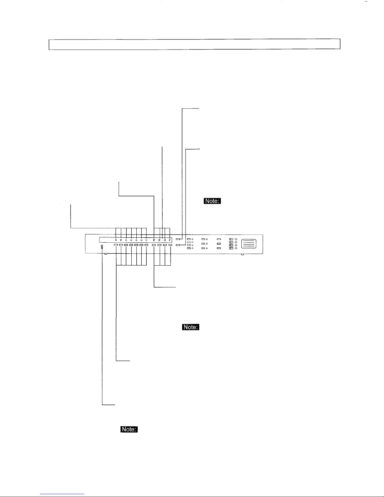
FRONT PANEL FACILITIES
Second indicator
(colon)
Clock display
Day indicator
ADJUST key-Press the TIME key or DAY key with
ADJUST key continuously pressed to set a clock
for the current time.
00 SEC. key-Use this key to adjust a clock to
seconds. As soon as the key is pressed with the
ADJUST key pressed continuously, the clock is
reset to zero second and a new counting of
second gets started. Pressing the key when the
clock counting is between 30 and 59 seconds
automatically increases the minute indication by
The 00 SEC. key works only when the program switch is
set to OPERATION.
Clock setting keys-Use this keys to set a clock for the current
hour. To do this, press this setting with the ADJUST key
pressed continuously. This setting is also used to set the
time of the timer program.
Each time the TIME key is pressed, the number over
the setting pressed increases by one.
Day setting keys-to program a current day of the week into the
timer, press this setting with the ADJUST key pressed continuously.
This key is also used to register the day of the week of timer
program.
Program switch-Set this switch to OPERATION when setting a clock for the
current hour or when letting the timer work. Set the switch to PROGRAM to
perform programing.
The timer does not operate if the program switch is set to PROGRAM. Be
sure to set it to OPERATION normally.
3
Page 4
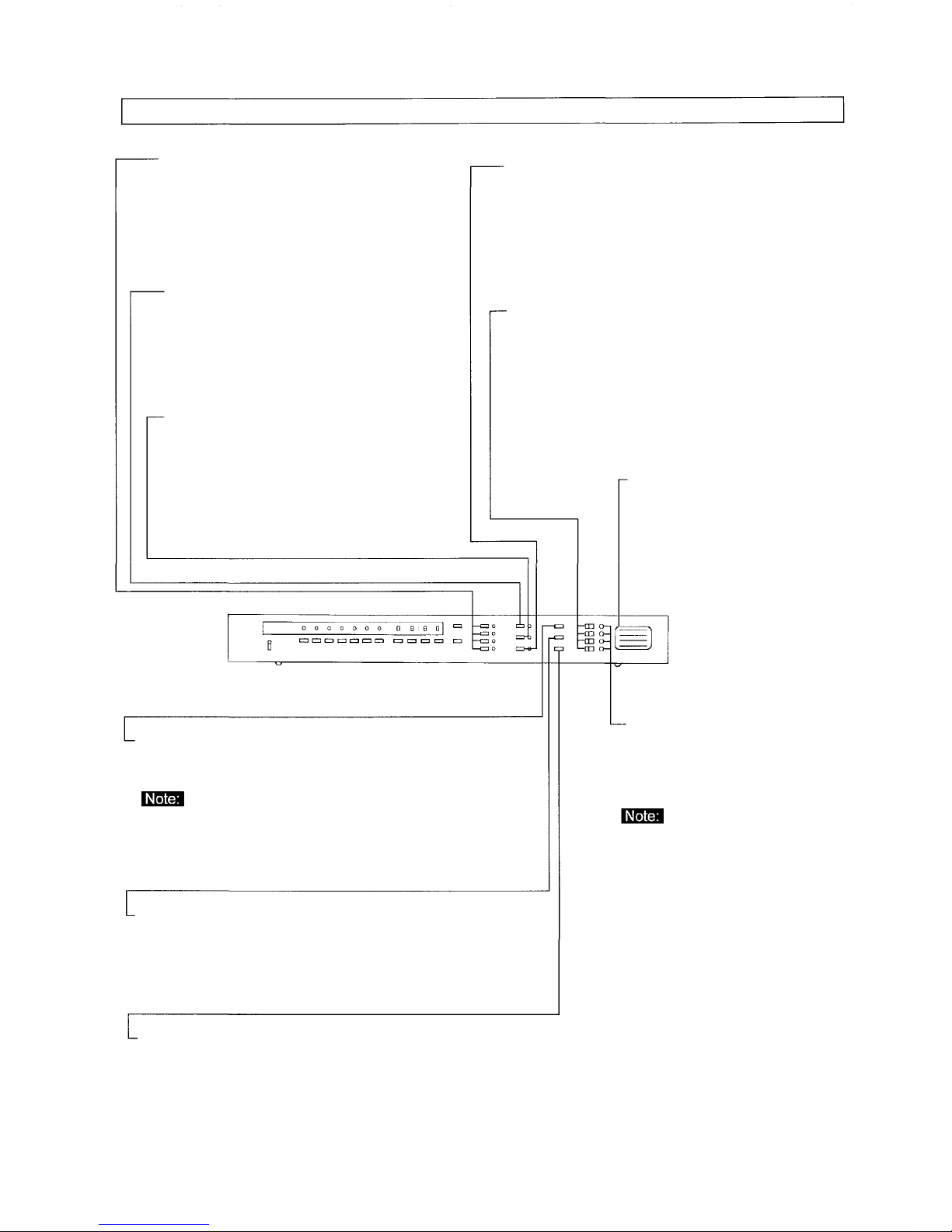
FRONT PANEL FACILITIES
CHANNEL key-Use this key to select the
program output. Pressing the key causes
the corresponding channel indicator on
the right side of each key to come on.
DAY key-This key is used to register a
weekly program. Press the key, and
the DAY indicators flash, allowing a
day of the week to be set with the day
setting under each indicator.
TIME key-Press this key to register
the clock program, and the clock
display flashes. Set hours with the
clock settings under the display.
PAUSE key-When it is desirable to stop the clock
operation temporarily on a certain day because that
day falls on a holiday, this can be accomplished by
using this key. After pressing this key (the day
indicators flash), press the desired day setting.
AUTO/OFF switch-Each individual output channel
can be connected and disconnected with this
switch. Setting the switch to ON allows the output
channel of that switch to operate at the programed
time. When set to OFF, the output operation stops.
Output identification label-This
label is supplied with unit. Write
the names of programs of or
equipment connected to each
output channel in the label.
STORE key-Press this key to store the
day of the week or hours set under the
day, time or pause mode.
No programs can be stored in a built-in
memory unless the memory key is
pressed.
CHECK key-This key checks the day of the week or hour for
proper registration. The corresponding date indicator comes
on when checking the day of the week. Also, each time the
CHECK key is pressed, the clock display shows the
programed times from the earliest hour to the latest in
sequence.
CANCEL key-This key cancels the stored day of the
week or hour. To cancel the day of the week, press
the CHECK key to call up the day of the week and
cancel it with the CANCEL key. Similarly, the stored
hour can be cancelled with both the CHECK and
CANCEL keys.
MANUAL switch-Use this switch to
manually deliver the output
regardless of actual program.
Pressing this switch connects a
relay contact for five seconds.
1. The connected equipment can be
manually activated with this switch
regardless of program as well as
position of the AUTO/OFF switch.
2. This switch cannot be operated
during power outage.
4
Page 5
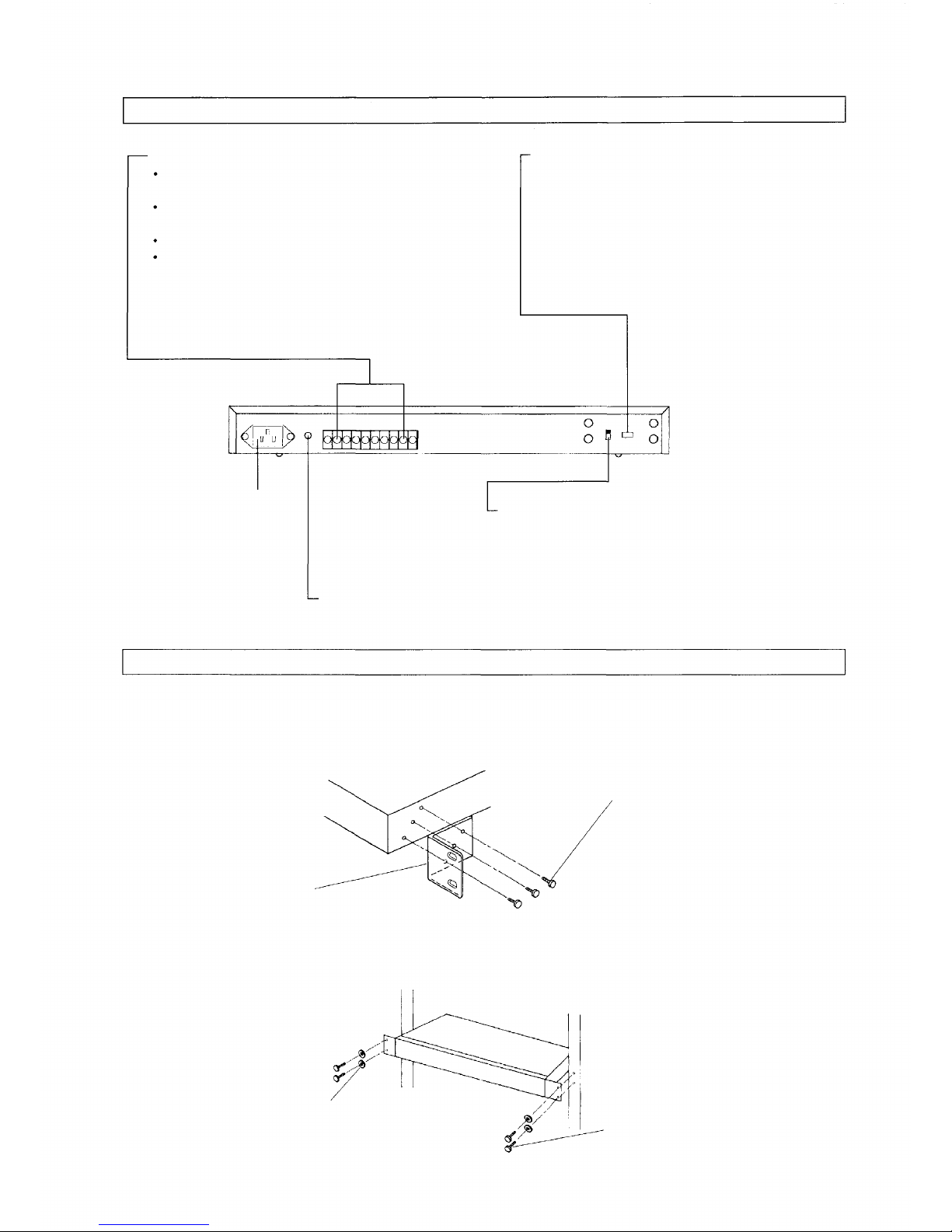
REAR PANEL FACILITIES
OUTPUT CHANNEL terminal
Output capacity : 24 V DC 0.5 A (resistance load)
Minimum load : 10 mV DC 10µA.
A relay contact connects for five seconds at the
programed time.
These relays are dry contacts.
Connect this terminal to start terminals of BGM
player or spot announcing machine, etc.
AC power inlet
Earth terminal-Be sure to ground unit.
CHANNEL ASSIGNMENT switch-Set each
switch to ON when assigning all of B, C and D
channels to the A channel. When, for example,
the B channel switch is set to ON, the A channel
relay contact connects at the time programed for
both A and B channel. In this event, the B
control output does not work.
MEMORY BACK UP switch-Be sure to set this switch
to ON after installation. This switch protects clock and
stored programs for approximately 100 hours during
power outage.
RACK MOUNTING
To mount the TT-104B in an equipment rack, the rack mounting bracket (optional) is required. Follow the
procedures below.
1. After removing rubber foot of the TT-104B, attach the bracket to the TT-104B.
Fixing screw (3 x 8)
supplied with the bracket
Rack mount bracket
2. Fix the TT-104B in the rack using screws supplied with the bracket. See the figure.
Rack
Fiber washer
supplied with the bracket
Fixing screw (M5 x 12)
supplied with the bracket
5
Page 6

REAR PANEL FACILITIES
SETTING THE CURRENT TIME
1. Plug power cord in wall outlet. Set the program switch to OPERATION. The clock display flashes to show
"0000" and at the same time, a warning tone beeps, indicating that the timer has to be set for current hour.
2. Set the rear-mounted MEMORY BACKUP switch to ON. The switch allows a clock to work and protects
stored programs during power outage, but no timer output is delivered.
3. Press the DAY setting key (from Monday to Sunday) with the ADJUST key continuously pressed to set a day
of the week. The corresponding date indicator comes on, while a colon (second indicator) in indication
"00:00" that appears in the clock display begins to flash at time intervals of one second, indicating that a clock
is working. The beep stops.
4. Pressing the ADJUST key continuously, press the clock settings (HOUR and MIN. keys) to set a clock for
current hour. The number increases by one each time the setting is pressed. If the unreal hour is set which is
not in a range from zero hour (00:00) to 23 hundred 59 hours (23:59), both the date indicator and clock
display flash and at the same time, a warning tone beeps. In such a case, correct the hour.
5. Press the 00 SEC. key, while pressing the ADJUST key continuously. This resets the second of a clock to
"00". Pressing the 00 SEC. key when a clock second accounting is between 30 and 59 seconds increases
the minute indication by one. The minute indication does not change when the second is between 0 and 29
seconds. (The clock display shows no second, but the clock is working in second.)
HOUR CORRECTION
Check to confirm that the program switch is set to OPERATION. Pressing the ADJUST key continuously, press
the clock reset key the moment the radio time signal tells zero second. This allows the clock to be timed to the
moment if variation is within ± 30 seconds. If the clock varies more than 30 seconds, use the time adjustment
as well as clock settings so that the clock display indicates the correct hour.
The second of the clock is not reset to zero second even when a day of the week and the current hour are set.
6
Page 7

OPERATION
PROGRAM REGISTRATION
The output of the TT-104B is a relay contact that makes for five seconds at the programed time. The relay
contact cannot be kept connected or disconnected by programs. Take care that equipment to accept the pulse
output are connected to the timer.
1. Enter programs in the program table supplied with unit. Lump the programs together per equipment
connected and assign the output channel to each equipment. If the same equipment are used but their
programs are not the same, assign different output channels.
Example.
If it is so programed as to sound a chime both in the morning and in the afternoon of Monday through Friday,
and in the morning of Saturday, and to play a piano accompaniment to the morning announcement every
morning from Monday through Saturday, write on the table as follows:
PROGRAM TABLE
Output channel
Equipment
Chime
Spot announcing machine
7
Page 8

OPERATION
2. Program registration
Register the programs according to the contents written in the program table.
Set the program switch to PROGRAM.
Press the A channel key.
OPERATION
PROGRAM
The output channel indicators (A,B,C,D) and Pause
indicator flash.
A
Press the DAY made key.
DAY
Designate a day(s) of the week.
MON
TUE
WED
THU
FRI
When the wrong day setting has been pressed, press the same setting again, and the corresponding
day indicator goes out. Then press the correct setting.
Press the MON setting. Its indicator comes on.
Press the TUE setting. Its indicator comes on.
Press the WED setting. Its indicator comes on.
Press the THU setting. Its indicator comes on.
Press the FRI setting. Its indicator comes on.
This causes the A channel indicator to come on and both
the date and clock made indicators to flash.
The day made indicator comes on. At the same time, the
day indicators from Moday to Sunday flash.
Register the day of the week by pressing the STORE key.
STORE
(The contents of the programs are not stored without pressing the STORE key.)
Press the TIME mode key.
TIME
8
The clock display indicates "PASS". At this point, all days from Monday to
Friday have been registered into the A channel.
The time mode indicator comes on. At the same time, a dotted line
" — — — — " flashes in the clock display.
Page 9

OPERATION
Set a clock for 08:55.
HOUR
(one hour's digit)
Press the HOUR key (one hour's digit) 8 times.
The clock display shows "0800".
MIN.
MIN.
Register the hour 08:55.
Press the STORE key.
STORE
(The content of the program is not stored without pressing the STORE key.)
Repeat steps
Pressing the STORE key to register the unreal hour other than one from 00:00 to 23:59
causes characters "Err" to appear in the clock display and the attempt of its registration is
refused. Correct the hour and register it again.
(Ten minute's digit)
(one minute's digit)
and
to register all the hours from 09:00 to 17:30.
Press the MIN. key (ten minute's digit) 5 times.
The clock display shows "0850".
Press the MIN. key (one minute's digit) 5 times.
The clock display shows "0855".
The word "PASS" appears in the clock display, indicating the
hour 08:55 has been registered into the A output channel.
When one same hour is registered twice, characters "Err" are indicated in the clock display.
If a registration attempt is made in excess of the program capacity (30), the word "End"
appears in the clock display, refusing the registration.
Repeat steps
through
PROGRAM CHECK, CORRECTION AND CANCELLATION
After finishing program registrations, check the program contents.
Shift the program switch back to PROGRAM.
OPERATION
PROGRAM
to register days of the week and hours into both B and C channels.
The output indicators of A, B, C and D channels as well as the
pause indicator comes on.
9
Page 10

OPERATION
Press the A channel key to select the A channel.
A
Put the timer in the day mode by pressing the DAY mode key.
DAY
Press the CHECK key.
CHECK I
The A channel indicator comes on, while both the date and clock
mode indicators flash.
The day mode indicator comes on and at the same time, day
indicators from Monday to Sunday flash.
The indicator of the registered day of the week comes on.
....... To step (9) to change the day of the
....... To step (10) to cancel the day of the
week.
week.
Press the TIME mode key.
TIME
Check the hour.
CHECK
Move to the next step to cancel the registered hour.
10
The time mode indicator comes on and at the same time, a
dotted line " – – – – " flashes in the clock display.
Each time the CHECK key is pressed, the registered hour is
shown in the clock display starting first with the earliest hour to
the latest in sequence. Pressing the check key when the last
hour is indicated causes the word "End" to appear in the clock
display, returning the indication to the first hour.
..... To step (8) to correct hour.
Page 11

OPERATION
When you wish to cancel the registered hour, press the CHECK key to get that hour in the
clock display.
CANCEL
Pressing the CHECK key when no hour is registered results in "End" being indicated in
the display, with "Err" indicated when the CANCEL key is pressed.
Correction of the hour.
CANCEL
HOUR
MIN.
STORE
Pressing the CANCEL key indicates the word "PASS" in the
display and cancels that hour. In this event, that cancelled hour
remains indicated in the display. Further cancellations can be
achieved in a similar manner by using both the CHECK and
CANCEL keys.
Press the CHECK key till that hour appears in the display.
Press the CANCEL key for cancelling the indicated
hour and then set the new hour using the clock settings.
Register the new hour with the STORE key.
(Be sure to cancel the previous hour when correcting it.)
Correction of the day of the week.
STORE
Press the CHECK key, and the day indicator of the registered day of
the week comes on. After pressing the desired date setting, press the
STORE key.
ENTIRE PROGRAM CANCELLATION
It is impossible to simultaneously cancel all the programs registered into all channels. Cancellation is only
possible for each channel (A, B, C and D). Follow the procedures below to cancel the A channel time program.
Set the program switch to PROGRAM.
OPERATION
PROGRAM
The A, B, C, and D output indicators and pause indicator
flash.
11
Page 12

OPERATION
Press the A channel selector.
A
Press the TIME mode key.
TIME
Press the CANCEL key with the A channel selector continuously pressed.
A
CANCEL
Similarly, the whole time program registered into each of the B, C and D channel can be cancelled. For the day
of the week, perform individual cancellations as instructed in the section 4 under the heading of PROGRAM
This causes the A channel indicator to come on and both the DAY
and TIME mode keys to flash.
The TIME mode indicator comes on and a flashing dotted line
" — — — — " is indicated in the display.
The word "PASS" appears in the display, indicating that the whole time
program registered into the A
channel has been cancelled.
PROGRAM OPERATION
OPERATION
PROGRAM
Be sure to set the program switch to OPERATION
after programming is finished. The timer does not
work if the switch is set to PROGRAM.
PAUSE MODE
The PAUSE key is used to temporarily make the timer not to function on particular days.
This is possible for up to the 7th day from the day of registration.
No output is delivered from the timer on a day set for pause.
After the pause day is over, the timer automatically returns to the normal state.
Use the pause function in such a case as the following example.
Example. Today is Friday and we want to stop the timer operation on Monday through Wednesday of next week
since our office is closed on these three days due to holidays.
(When it is on Monday that Monday is registered for pause mode, the pause day is a Monday of the following
week.)
Follow the procedures below to make Monday through Wednesday the pause days as in the example.
12
Page 13

OPERATION
Set the program switch to PROGRAM
Press the PAUSE key.
OPERATION
PROGRAM
The channel indicators (A, B, C and D) and pause mode
indicator flash.
PAUSE
Designate a day(s) of the week.
MON
TUE
WED
Press the STORE key.
STORE
(The contents of the program are not registered unless the STORE key is pressed.)
Its indicator comes on, while the date indicators from
Monday to Sunday flash.
Press the day settings of Monday, Tuesday and Wednesday,
and each corresponding day indicator comes on.
When the wrong day setting has been pressed, press that setting
again. The date indicator goes out.
The word "PASS" appears in the clock display, indicating that the
three days have been registered for pause.
When the current day is set after the pause registration, perform the new pause registration.
Set the program switch to OPERATION after finishing programing.
USING FRONT-MOUNTED AUTO/OFF
This switch is used to stop actions of an output relay regardless of the timer program. When the switch is set to
AUTO, the relay functions as programed. Setting the switch to OFF does not activate the relay. The switchover
is possible per channel.
13
Page 14

OPERATION
USING MANUAL SWITCH
Use this switch to activate the output relay regardless of the timer program. Pressing the switch causes the
output relay to connect for five seconds. This is possible for each individual output. Use this switch when
performing a test at time of equipment installation or for other purposes that necessitate the manual relay
activation regardless of the timer program.
The switch does not work during power outage.
The switch works regardless of the front-mounted output AUTO/OFF switch.
USING REAR-MOUNTED CHANNEL ASSIGNMENT
This switch is used to switch over from the B, C or D channel to the A channel. When the B channel switch is
set to ON, the B program output is delivered from the A channel, with the A program output delivered from the A
channel. In this event, no output is delivered from the B channel.
Example 1
A
8:30
9:30
10:30
B
9:00
10:00
11:00
C
12:00
Given that each of the output channels is programed
as Example 1, the output is delivered from each
channel as follows.
If all the switches are set to OFF.
A channel: Output is delivered at 8:30, 9:30 and 10:30.
B channel: Output is delivered at 9:00,10:00 and 11:00.
C channel: Output is delivered at 12:00.
If both the B and C switches are set to ON.
A channel: Output is delivered at 8:30, 9:00, 9:30,10:00,
10:30,11:00, and 12:00.
No output is delivered from both the B and C channels.
1. Rear-mounted CHANNEL ASSIGNMENT switch vs. front-mounted AUTO/OFF switch. The AUTO/OFF
switch is effective for the program registered into each output.
AUTO OFF
A
B
C
D
A channel delivers output at 9:00, 10:00 and 11:00.
B channel delivers no output.
C channel delivers output at 12:00.
If the CHANNEL ASSIGNMENT switch of B
channel is set to ON and the AUTO/OFF switch
of A channel to OFF in Example 1.
Since the A AUTO/OFF switch is set to OFF, the output is not delivered from the A
channel at 8:30, 9:30 and 10:30 as programed.
Since the B channel is switched over to the A channel, the A channel delivers output at
9:00, 10:00 and 11:00, the hours programed into the B channel.
14
Page 15

OPERATION
If the A channel MANUAL switch is pressed under these conditions, the A output relay makes for five seconds.
Pressing the B channel MANUAL switch causes the A channel relay to make for five seconds because the B
output is switched over to the A channel.
2. Use the rear-mounted output assignment switch in such cases as shown below:
To allow one single equipment to process four different programs through combined use of the output
assignment switch and the front-mounted output ON/OFF switch:
When, for example, the school has the Westminster chime and they want to utilize it for the following four
different programs
1) Ordinary school hour program (Monday to Friday)
2) Saturday program
3) Temporary shorter school hour program
4) Examination day program
1) register the ordinary school hour program into the A channel. (Register Monday through Friday.)
2) register the Saturday program into the B channel. (Register Saturday.)
3) register the temporary shorter school hour program into the C channel. (Register Monday
through Saturday.)
4) register the examination day program into the D channel. (Register Monday through Saturday.)
Set the CHANNEL ASSIGNMENT switches (B, C and D) to ON.
1) To operate the ordinary school hour program and Saturday program, set the AUTO/OFF switch to AUTO for
A and B channels, and to OFF for C and D channels. This allows the ordinary school hour program to be
operated on Monday through Friday, and the Saturday program on Saturday.
AUTO OFF
A
B
C
D
2) To operate the shorter school hour program, set the AUTO/OFF switch of the C channel to AUTO, while
setting it to OFF for all the other channels.
AUTO OFF
A
B
C
D
15
Page 16

OPERATION
3) To operate the examination day program, set the AUTO/OFF switch of the D channel to AUTO, and those of
other channels to OFF.
Thus, by shifting the AUTO/OFF switches different programs can be readily operated.
If exceeding per-channel program capacity of 30. When, for example, a frequently-used spot announcing
machine needs to be activated 80 times a day.
AUTO OFF
A
AUTO OFF
A
B
C
D
Set the rear-mounted CHANNEL ASSIGNMENT switches
of both B and C channels to ON.
B
C
D
This expands a program capacity to 80, with 30 being programmable into A channel, another 30 into B channel
and 20 into C channel.
POINTS TO REMEMBER
1) All the indications go out at time of power outage. However, a clock works normally and stored programs are
protected. No relay output is produced. After power restoration, the timer works normally and indicates the
current hour.
2) A clock and stored programs are maintained for about 100 hours during power outage. If the clock display
flashes to indicate "0000" with beep after power restoration, this indicates that the battery has run down. In
such a case, set a clock for the current hour and register the program again.
3) The 100-hour power outage protection is subject to the battery being kept fully charged. It takes about 200
hours to fully charge the battery. Frequent occurrence of power outage shortens the 100-hour protection
time.
OUTPUT RELAY
Output is a no-voltage (dry) make contact.
The relay makes for five seconds at preset time (pulse output system).
Output relay contact capacity :
Maximum: 24 V DC 0.5 A (resistance load)
Minimum : 10 mV DC 10 µA
Set the front-mounted AUTO/OFF switches of A, B,
and C channels to AUTO and that of D channel to
OFF.
16
Page 17

SPECIFICATIONS
Power requirements :
Power consumption :
Power outage protection period :
Program capacity :
Programmable items :
Number of channels :
Output system :
Contact capacity :
Clock accuracy :
Items indicated in display :
Special functions :
Dimensions :
Weight :
Ambient temperature :
* Specifications are subject to change without notice.
Accessories:
TT-104B L 110~120 V AC 50/60 Hz
TT-104B H 220~240 V AC 50/60 Hz
3 watts
100 hours
30 steps per channel
Day of the week, hour, minute, output channel
4 channels (A,B,C,D)
No-voltage (dry) make contact (5 seconds make output)
24 V DC, 0.5 A
± 5 seconds per month (25 °C)
Day of the week, hour & minute
• Entire program cancellation
• Output switchover
• Pause mode
• Warnings by tone and indication
420 (W) X 228 (D) X
(16.5" X 9.0" x 1.8") inch
Approx. 2.5 kg (5.5 Ibs)
0°C-50°C (32°F -122°F)
Power cord
Operating Instructions
Program table
Output identification label
44.5
(H) mm
DIMENSIONAL DIAGRAM
mm (inch)
17
Page 18

TOA Corporation
Printed in Japan
133-05-276-50
 Loading...