

Page 1
TS-800/900
Infrared Wireless Conference System
COOKBOOK
Page 2

GENERAL DESCRIPTION
(1) Objectives
• With the aim of enhancing the lineup of the TS-700 Series currently on the
market, two series of conference system that employ the infrared
communication method are offered.
• Like the TS-700 Series, the new series target small-scale, temporary, or
committee meeting conference rooms. Designed to meeting the
requirements arising from recent merger wave among municipalities, they
are most suitable for new installation at city halls as well as tentative
installation needs to cope with a temporary increase in the number of
assemblymen at the time of the merger.
• The TS-800 Series represents a cordless version of the TS-700 Series.
Thus, its functions are almost identical with those of the TS-700.
• The TS-900 Series, a high-end model, is equipped with additional
functions such as a voting function.
General Description
(2) Wh y infrared comm unication method?
• The infrared communication method frees users from worries about
eavesdropping and radio interference inherent to radio wave-based
wireless communications.
• Place a single wall in between, and what is being discussed in the
conference room will never be heard outside. For the same reason,
it is possible to use two or more systems simultaneously in adjoining
conference rooms.
(3) Advantages of the cordless system
• Installation work is simplified. Wiring between the Central unit and the
Transmission/Receiver unit is all that's necessary. Wiring is easily done
with a single coaxial (BNC-BNC).
•A cordless system allows easy system installation and removal, greatly
reducing the workload associated with relocation and layout changes.
• Because no wiring to the conference units is necessary, the system is free
from troubles, such as deterioration and a break in the wiring, that are
caused by repeated installations and removals.
• The Transmitter/Receiver unit can be mounted on a microphone stand, to
create a tentative system without requiring installation work.
1
-1
Page 3

GENERAL DESCRIPTION
The number of the Chairman and Delegate units can be varied according to fit the
●
number of participants. (TS-800 Series: up to 64 units; TS-900 Series: up to 96 units)
Up to 16 Transmitter/Receiver units (when using TS-905 units only) and up to 12
●
TS-907 units (including instances where TS-905 and TS-907 are used in combination)
can be installed to create stable communication environment even in a large
conference room.
Designed for use in a high-ceilinged room, the TS-907 Transmitter/Receiver is capable
●
of communications in a room with ceiling height of more than 5 meters and less than 7
meters.
The Speaker Restriction function (1, 2, or 4) prevents confusion resulting from
●
simultaneous speeches by participants.
The speech system selection (first-in-first-out, last-in-first-out, or last-in-first-out after
●
2nd unit) enables the system to handle conferences in a wide range of situations.
The Chairman unit features a priority speech function. By talking while pressing the
●
priority speech key, the Chairman unit can override Delegate units.
Features
To prevent a howl, the monitor speaker of both Chairman and Delegation units is
●
turned off while the units are in use.
The Central unit can be used in combination with wired microphones or output source
●
equipment, depending on the purpose.
The 900 Series features a threefold vote function, which facilitates voting and counting
●
of "Yes," "No," and "Abstention" votes.
Both Chairman and Delegate units work either on the rechargeable lithium-ion battery
●
or AC current. With a fully charged battery, the unit operates for about 10 hours.
(assuming that the speech time amounts to one-third of the whole length of the
conference)
Dedicated microphones for Chairman and Delegate units are available in two types:
●
"standard" (primarily for use in a sitting position) and "long" (primarily for use in a
standing position).
1
-2
Page 4
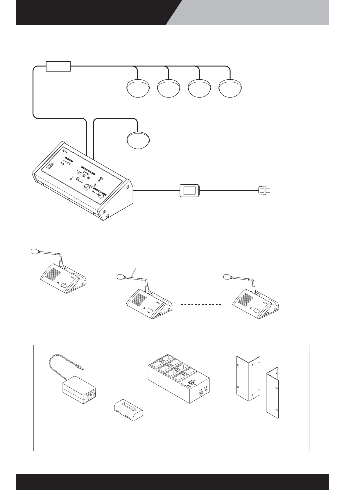
SYSTEM EQUIPMENT CONFIGURATION TS-800 SERIES
SYSTEM EQUIPMENT CONFIGURATION
Distributor
YW-1024 (4-branch distributor)
or
YW-1022 (2-branch distributor)
C
E
N
T
R
A
L
U
N
I
T
TS
-8
0
0
Note: Connectable up to 16 units (TS-905) and up to 12units (TS-907)
Infrared transmitter/receiver
TS-905/TS-907
Infrared transmitter/receiver
TS-905/TS-907
Central unit
TS-800
C
HA
I
RM
A
N
UN
I
T
T
S
8
0
1
Chairman unit
TS-801
AC adapter
(supplied with the TS-800)
Microphone (standard) TS-903
or
Microphone (long) TS-904
D
E
L
E
G
A
T
E
U
N
I
T
T
S
8
0
2
Delegate unit
TS-802
Power cord
(supplied with the TS-800)
D
E
L
E
G
A
T
E
U
N
I
T
T
S
8
0
2
8
AC adapter AD-0910
(for TS-801/802)
Lithium-ion battery BP-900
(for TS-801/802)
Battery charger BC-900
(for BP-900)
2
-1
Rack mounting bracket MB-TS900
(for TS-800)
Page 5
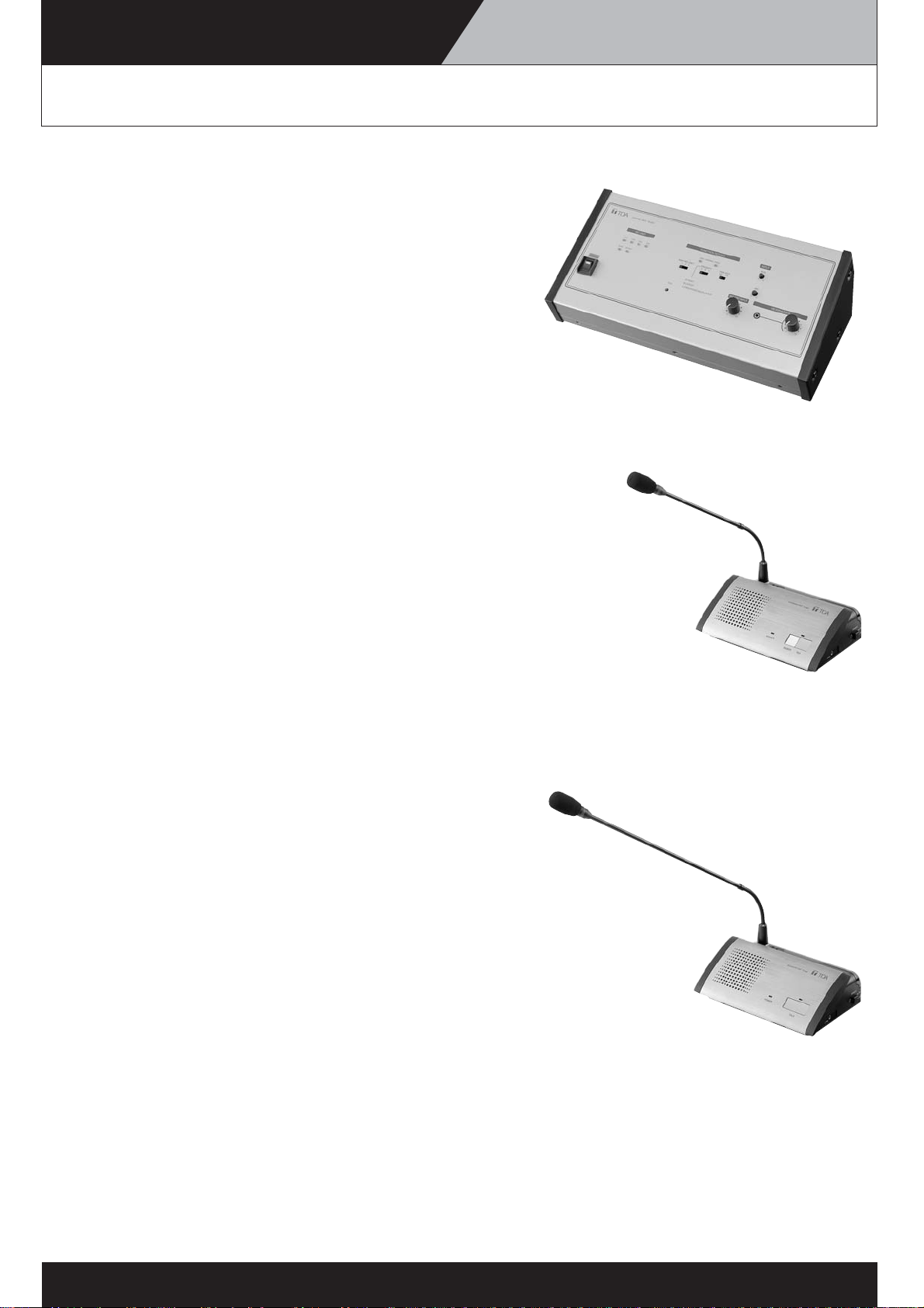
SYSTEM EQUIPMENT CONFIGURATION TS-800 SERIES
SYSTEM EQUIPMENT CONFIGURATION
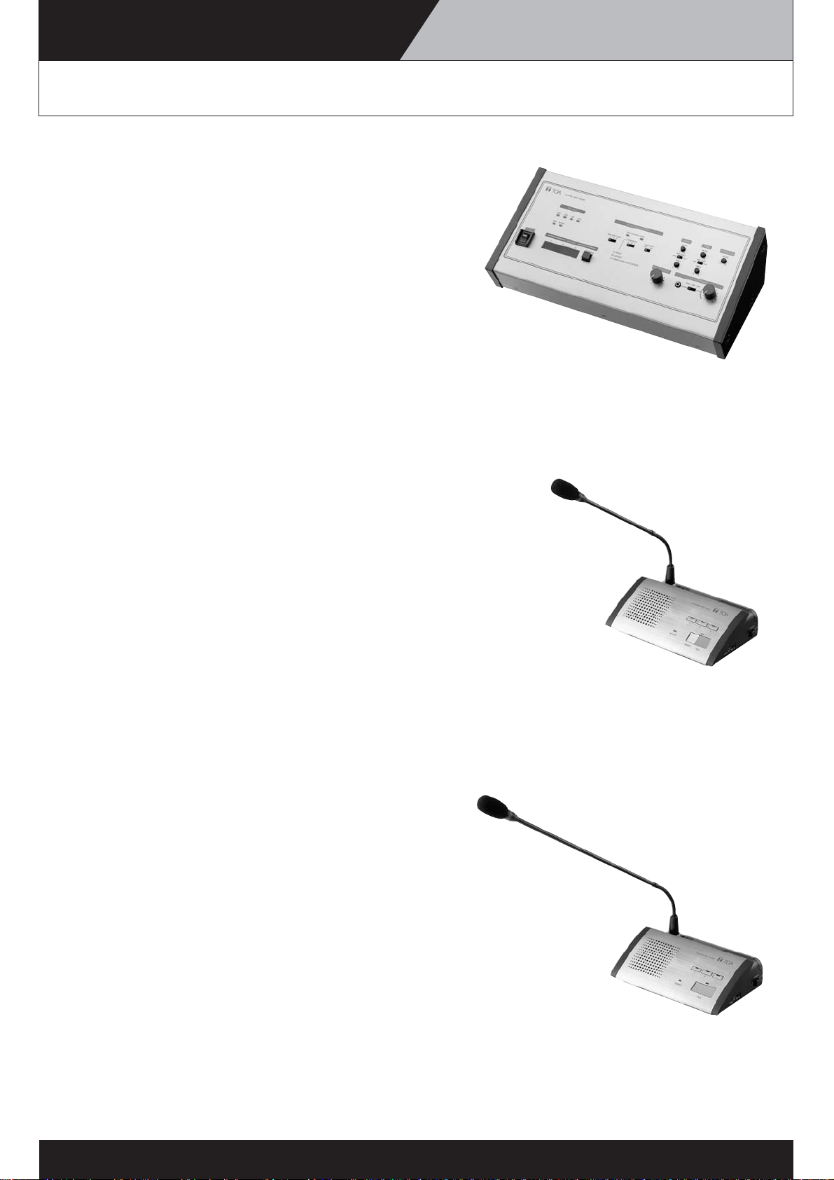
Central Unit: TS-800
• The unit is used to select the speech system as well as set the
number of participants allowed to talk.
• The unit can handle up to 64 conference units (TS-801, TS-802).
• The unit can be connected with up to 16 Transmitter/Receiver
units (TS-905) to communicate with conference units.
• The unit can be externally controlled by a PC. (Note: Requires
custom-ordered software)
• The unit can be mounted either on a tabletop or in a rack (rack
mounting brackets are option).
Chairman Unit: TS-801
• Cordless feature makes it easy to use the unit for conferencing
in a temporary meeting room or relocate the unit when the room
layout has been changed.
• The priority speech function allows the Chairman unit to take
speech priority over Delegate units (TS-802).
• The unit features speech and remaining battery charge
indicators.
• Either the battery (lithium-ion battery) or AC adapter can be
used as a power source for this unit.
• There are two optional microphones to choose from: standard
(TS-903) and long (TS-904).
Delegate Unit: TS-802
• Cordless feature makes it easy to use the unit for conferencing
in a temporary meeting room or relocate the unit when the room
layout has been changed.
• Speech and remaining battery charge indicators are provided.
• Either the battery (lithium-ion battery) or AC adapter can be
used as a power source for the unit.
• There are two optional microphones to choose from: standard
(TS-903) and long (TS-904).
8
2
-2
Page 6
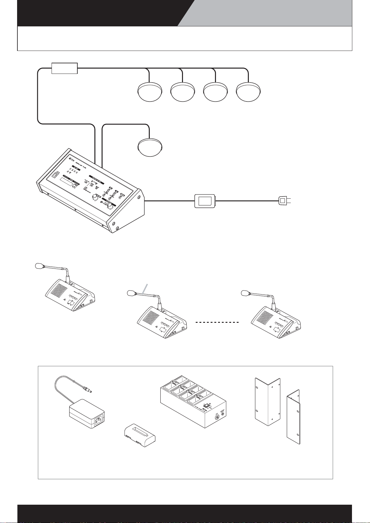
SYSTEM EQUIPMENT CONFIGURATION TS-900 SERIES
SYSTEM EQUIPMENT CONFIGURATION
Distributor
YW-1024 (4-branch distributor)
or
YW-1022 (2-branch distributor)
Note: Connectable up to 16 units (TS-905) and up to 12units (TS-907)
Infrared transmitter/receiver
TS-905/TS-907
Infrared transmitter/receiver
TS-905/TS-907
Central unit
TS-900
Chairman unit
TS-901
AC adapter
(supplied with the TS-900)
Microphone (standard) TS-903
or
Microphone (long) TS-904
Delegate unit
TS-902
Power cord
(supplied with the TS-900)
8
AC adapter AD-0910
(for TS-901/902)
Lithium-ion battery BP-900
(for TS-901/902)
Battery charger BC-900
(for BP-900)
2
-3
Rack mounting bracket MB-TS900
(for TS-900)
Page 7
SYSTEM EQUIPMENT CONFIGURATION TS-900 SERIES
SYSTEM EQUIPMENT CONFIGURATION
Central Unit: TS-900
• The unit is used to select the speech system and set the
number of participants allowed to talk.
• The unit features the threefold vote function.
• The unit is equipped with two channels (MAIN, SUB) for speech
output to conference units.
• The unit can handle up to 96 conference units (TS-901, TS-902).
• The unit can be connected with up to 16 Transmitter/Receiver
units (TS-905) to communicate with conference units.
• The unit can be externally controlled by a PC. (Note: Requires
custom-ordered software)
• The unit can be mounted either on a tabletop or in a rack (rack
mounting brackets are optional).
Chairman Unit: TS-901
• Cordless feature makes it easy to use the unit for conferencing
in a temporary meeting room or relocate the unit when room
layout has been changed.
•The priority speech function allows the Chairman unit to take
speech priority over Delegate units (TS-902).
•A voting key is provided.
• Selection of the speech input channel is possible (MAIN or
SUB).
• Speech and remaining battery charge indicators are provided.
• Either the battery (lithium-ion battery) or AC adapter can be
used as a power source.
• There are two optional microphones to choose from: standard
(TS-903) and long (TS-904).
Delegate Unit: TS-902
• Cordless feature makes it easy to use the unit for conferencing
in a temporary meeting room or relocate the unit when room
layout has been changed.
•A voting key is provided.
• Selection of the speech input channel is possible (MAIN or
SUB).
• Speech and remaining battery charge indicators are provided.
• Either the battery (lithium-ion battery) or AC adapter can be
used as a power source.
• There are two optional microphones to choose from: standard
(TS-903) and long (TS-904).
8
2
-4
Page 8
SYSTEM EQUIPMENT CONFIGURATION TS-800/TS-900 SERIES
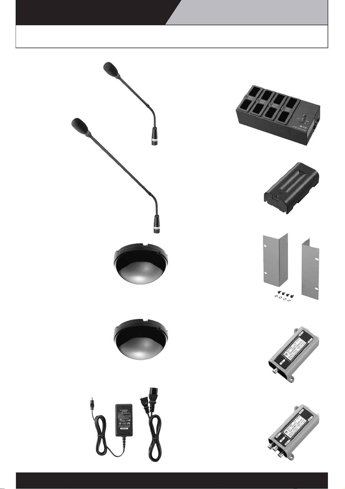
Accessories
Standard microphone: TS-903
•A microphone designed for exclusive
use with conference units.
• The overall length is 368 mm.
Long microphone: TS-904
•A microphone designed for exclusive
use with conference units
• The overall length is 518 mm.
(for both TS-900 Series and TS-800 Series)
Dedicated battery charger: BC-900
•A dedicated battery charger for use with the BP-900
lithium-ion battery.
• Capable of simultaneously
charging eight BP-900
batteries.
• Recharge time is
about five hours.
Lithium-ion battery: BP-900
•A battery designed for exclusive use
with conference units.
•When fully charged, the BP-900
operates for about 10 hours.
• Recharging the BP-900
requires the dedicated battery
charger BC-900.
Transmitter/Receiver unit: TS-905
•A Transmitter/Receiver unit that
performs communications
between the Central unit and
conference units.
• The unit can be mounted not only
to the ceiling and wall but also on
the microphone stand for temporary installation.
• It has a coverage range of about 2.5 – 5.0 meters.
Transmitter/Receiver unit: TS-907
•A Transmitter/Receiver unit that
performs communications
between the Central unit and
conference units.
• The unit can be mounted not only
to the ceiling and wall but also on
the microphone stand for temporary installation.
• It has a coverage range of about 5.0 – 7.0 meters.
AC adapter
(for use with
conference units):
AD-0910
• An AC adapter designed
for exclusive use with
conference units.
Rack mounting bracket:
MB-TS900
•A dedicated rack
mounting bracket
to mount the Central units
(TS-900, TS-800) in a rack.
• The bracket allows mounting in
an EIA standard equipment rack
(4 sizes)
Distributor (2-branch distributor): YW-1022
•A distributor to be used for 2-branch
distribution of the coaxial cable
when more than one Transmitter/Receiver
unit is installed.
• It is used to connect 4 or more
Transmitter/Receiver units, or
to perform wiring to the ceiling with
a single cable.
Distributor (4-branch distributor): YW-1024
•A distributor to be used for 4-branch
distribution of the coaxial cable when more
than one Transmitter/Receiver unit
is installed.
• It is used to connect 4 or more
Transmitter/Receiver units, or
to perform wiring to the ceiling with
a single cable.
8
2
-5
Page 9
SYSTEM CONNECTION EXAMPLE TS-800
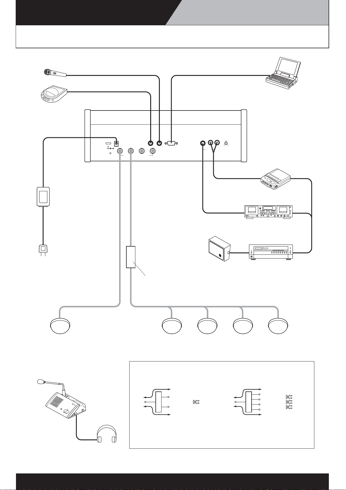
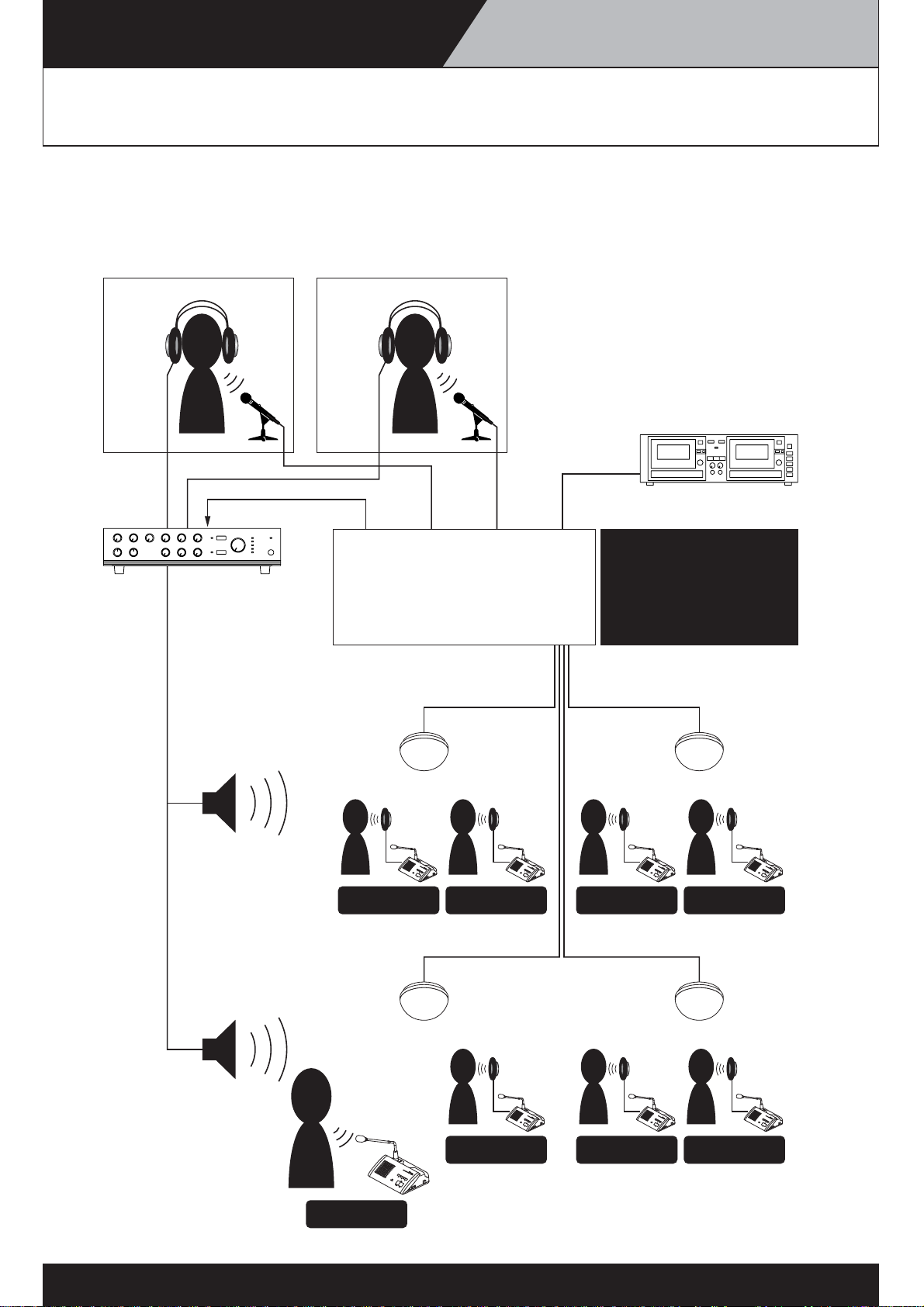
SYSTEM CONNECTION EXAMPLES
PC
Central unit TS-800
AC adapter
(supplied with the TS-800)
Power cord
(supplied with the TS-800)
DC24V 3A(MAX)
SHORT
INFRARED TRANSMITTER/RECEIVER
MIC RS-232C CHIME
AUX
REC OUT
Speaker Amplifier
Distributor
YW-1024 (4-branch distributor)
or
YW-1022 (2-branch distributor)
Cassette player
Alternate recording deck
22
Infrared transmitter/receiver
Chairman unit TS-801
or
Delegate unit TS-802
C
H
A
I
R
M
A
N
U
N
I
T
T
S
8
0
1
Headphone
TS-905/TS-907
Distributor block diagram
[YW-1022] [YW-1024]
Loss of 4.5dB
Mixing
Loss of 4.5dB
Note:
Distribution 1
Impossible
Distribution 2
Distributor
To avoid an increase in loss, do not perform connections
between distribution terminals.
3
-1
Mixing
Loss of 8.5dB
Distribution 1
Distribution 2
Distribution 3
Distributor
Distribution 4
Loss of 8.5dB
Impossible
Impossible
Impossible
Page 10
SYSTEM CONNECTION EXAMPLE TS-900
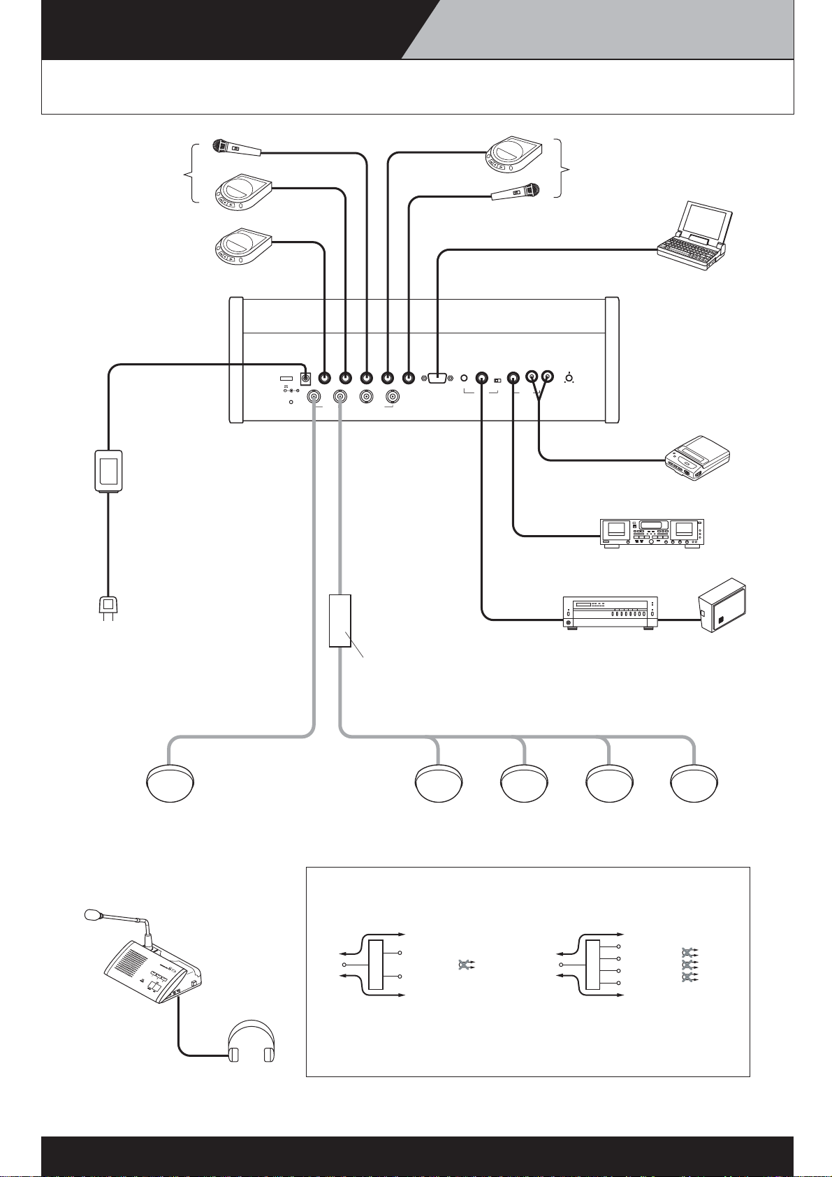
SYSTEM CONNECTION EXAMPLES
For the translation
language channel
For the base language
and translation language
channels
AC adapter
(supplied with the TS-900)
Power cord
(supplied with the TS-900)
DC24V 3A(MAX)
SHORT
Central unit TS-900
AUX2 MIC2 MIC1 EXT CONTROL LEVEL CHIME
AUX3
INFRARED TRANSMITTER/RECEIVER
AUX1
MIX CUT
AUX3
LINE OUT REC OUT
For the base language channel
PC
Cassette player
Alternate recording deck
Infrared transmitter/receiver
Chairman unit TS-901
or
Delegate unit TS-902
Headphone
Distributor
YW-1024 (4-branch distributor)
or
YW-1022 (2-branch distributor)
TS-905/TS-907
Distributor block diagram
[YW-1022] [YW-1024]
Loss of 4.5dB
Mixing
Distribution 1
Distribution 2
Distributor
Loss of 4.5dB
To avoid an increase in loss, do not perform connections
Note:
Impossible
Mixing
between distribution terminals.
Loss of 8.5dB
Distribution 1
Distribution 2
Distribution 3
Distributor
Distribution 4
Loss of 8.5dB
SpeakerAmplifier
Impossible
Impossible
Impossible
3
-2
Page 11
SYSTEM CONNECTION EXAMPLE TS-900 SERIES
System connection example for
bilingual conferencing (TS-900 Series)
The 2-channel monitor function enables to conduct a simple bilingual conference.
(Refer to the connections shown in the chart)
Interpreter’s booth (1)
English ➡ Japanese
[X]
Amplifier
Interpreter’s booth (2)
Japanese ➡ English
[Y]
LINE
MIC1 MIC2 REC
OUT
Central Unit TS-900
Transmitter/Receiver
Voice from
conference units
OUT
input/output
Recording equipment
Switch setting
MAIN: MIC UNIT ➡ CUT
SUB : MIC UNIT ➡ CUT
Floor speaker
(voice from conference units)
In this case, voice of [A] is output.
Monitor switch setting
Floor speaker
(voice from conference units)
In this case, voice of [A] is output.
[A]
[X]
Conference
unit TS-902
MAIN
Conference
unit TS-901
Transmitter/
Receiver
[X]
Conference
unit TS-902
Monitor switch setting
MAIN
Transmitter/
Receiver
[X]
Conference
unit TS-902
Monitor switch setting
MAIN
[X]
Conference
unit TS-902
Monitor switch setting
MAIN
[Y]
Conference
unit TS-902
Monitor switch setting
SUB
Transmitter/
Receiver
[Y]
Conference
unit TS-902
Monitor switch setting
SUB
Transmitter/
Receiver
[Y]
Conference
unit TS-902
Monitor switch setting
SUB
Speech in progress
4
-1
Page 12
SYSTEM CONNECTION EXAMPLE TS-900 SERIES
Sound Input/Output Diagram
(TS-900 Series)
Line Rec. OutMain Sound Sub Sound
Infrared
MIC1
AUX1
MIC2
AUX2
AUX3
Main Cut
Aux3 Cut
Sub Cut
4
Link
-2
Page 13
INFRARED SERVICE AREAS TS-800/TS-900
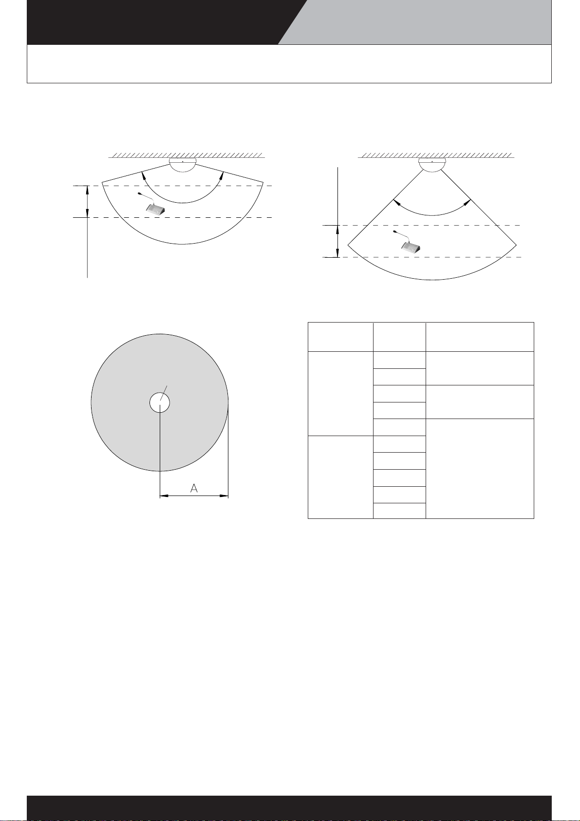
Infrared Transmitter/Receiver
[Side view]
TS-905 TS-907
150°
90°
5.0 – 7.0m
2.5 – 4.5m
[Top view]
Infrared transmitter/
receiver
[Optimal Coverage Areas]
Model No.
Ceiling Radius of
height coverage area (A)
2.5m
Approx. 7.0m
3.0m
TS-905 3.5m
Approx. 6.5m
4.0m
4.5m
5.0m
5.5m
TS-907 6.0m Approx. 6.0m
6.5m
7.0m
Care should be taken to ensure the Chairman/Delegate Units are within the optimal
coverage area of the Infrared Transmitter/Receiver unit.
The Infrared Transmitter/Receiver unit must not be installed behind a user or any other
obstacle, as infrared signals will be unable to reach it. The Infrared Transmitter/Receiver units
must be installed to ensure that two or more units will always be in straight sightlines from
the Chairman/Delegate units.
If only one Infrared Transmitter/Receiver unit is used for communication, reception may be
interrupted if the infrared signals are blocked, either by an individual or obstacle. A minimum
of two Infrared Transmitter/Receiver units is required for an installation to enable the
Chairman/Delegate to always be able to communicate with them.
5
-1
Page 14
INFRARED SERVICE AREAS TS-800/TS-900
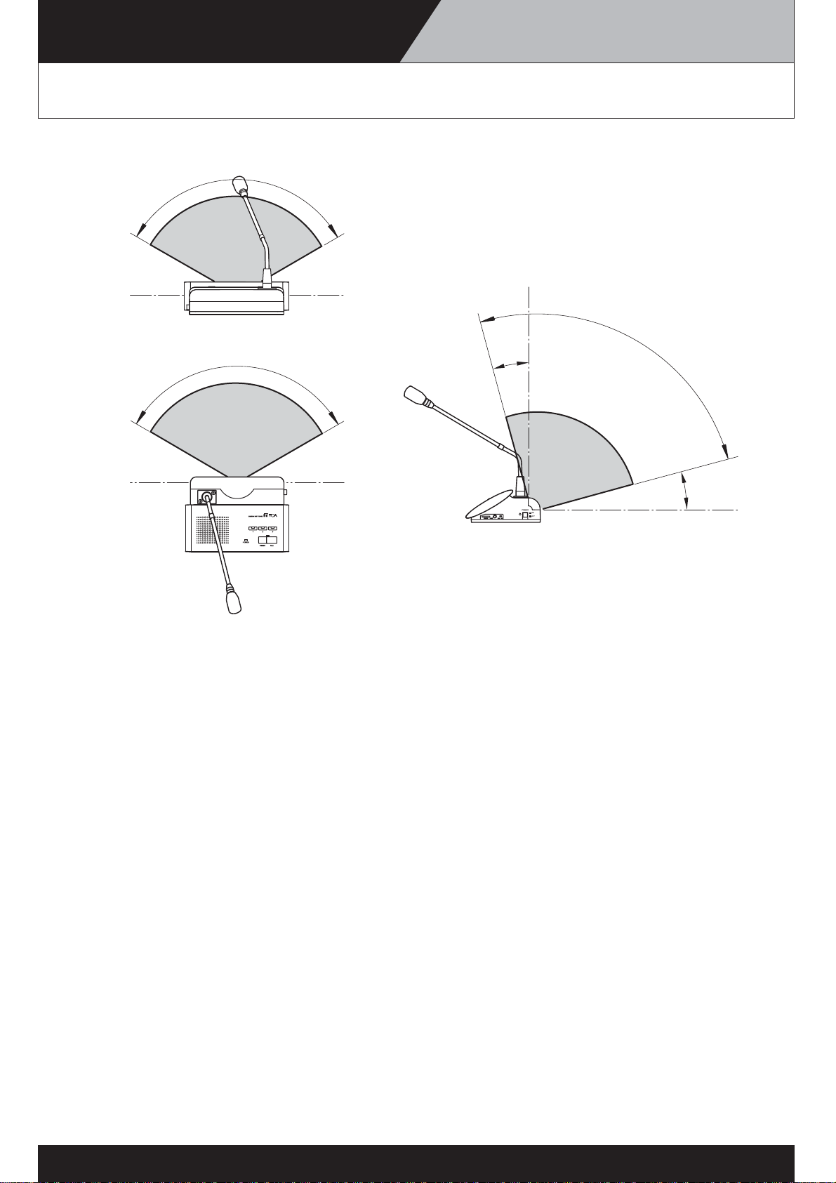
Chairman Unit and Delegate Unit
120°
15°
120°
Note:
The conference unit sends and receives signals only in the front direction. The conference
unit thus cannot communicate with Transmitter/Receiver units that are placed behind it. It is
important to set up the Transmitter/Receiver in front of terminals to be used.
90°
15°
5
-2
Page 15

EQUIPMENT THAT AFFECT THE OPERATION
TS-800/900 SERIES
Equipment that affect the operation of the
Conference System units
Equipment that cannot be used in the same location as the System units.
• Plasma displays
Plasma displays emit a large amount of infrared radiation to illuminate the screen. For this reason, if
the Transmitter/Receiver unit is installed near a plasma display, or if terminals are used in front of the
plasma display, communication failure and noise may occur.
• Infrared LANs
• Infrared microphone systems
• Infrared simultaneous interpreting systems
As with the TOA Infrared Conference System, these systems also use infrared light. Thus, if used in
the same location, they could interfere with each other. In some cases, it may be the TOA system that
fails; in other cases, it may be the other system that becomes inoperable.
• etc.
Equipment that might cause unstable operation of the System units.
• Lighting equipment (spotlights and downlights)
When direct light from a spotlight or downlight reaches the infrared signal receiver of the
Transmitter/Receiver unit, communication failure or noise may occur.
Fluorescent lights have little effect on the Transmitter/Receiver unit’s performance. However, if light of
the incandescent lamp (downlight) is very intense, it could result in a slight decrease in the signal
traveling distance or a rise in noise floor. This problem can be avoided by increasing the number of
Transmitter/Receiver units installed.
• Sunlight
When direct sunlight hits the infrared signal receiver of the Transmitter/Receiver unit, communication
failure or noise may result. In general, this problem can be avoided by using (installing) the unit away
from windows or by covering windows with curtains or blinds.
6
Page 16
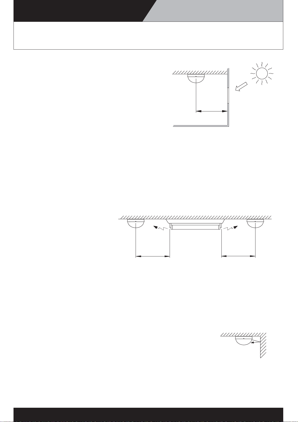
CAUTIONS IN INSTALLING TS-800/900 SERIES
Cautions in installing the
Transmitter/Receiver unit
1. Install the Transmitter/Receiver unit away from windows.
Install the unit 2 – 3 meters away from the nearest
window, so that the effect of sunlight is minimized.
Sunlight
2 – 3 m
Note:
When effective coverage range is sought, installation will naturally be toward the center of the room.
Caution should be exercised when installing the unit close to the wall or near the corner of the room
to make it inconspicuous. If it is not possible to secure the above-mentioned distance, shading
sunlight with curtains or blinds will work.
2. IInstall the Transmitter/Receiver unit away from lighting equipment.
Lighting equipment may emit infrared portion of the light spectrum (especially incandescent lamps).
Installing the unit at least 50 cm away from lighting equipment minimizes the interference.
Ceiling
Fluorescent lights
50 cm or more
Note:
If the lighting equipment is mounted higher than (behind) the Transmitter/Receiver unit, there is no
need to worry (as in a case of the lighting equipment mounted flush with the ceiling).
If light does not directly hit the infrared signal receiver of the Transmitter/Receiver unit, there is no
need to worry. with curtains or blinds will work.
50 cm or more
3. Do not install the unit in pr oximity to the wall, column, and other obstacles.
Avoid installing the Transmitter/Receiver unit in close proximity to the wall, column or obstacles.
The unit could malfunction by detecting own infrared signals that are reflected.
Note:
A distance of 20-30 cm will be adequate to make the unit unaffected. However, caution should be
exercised when highly reflective materials such as a mirror are involved.
In particular, caution should be exercised when installing the unit in a large room with a column
in the center.
7
-1
Page 17

CAUTIONS IN INSTALLING TS-800/900 SERIES
Cautions in installing the
Transmitter/Receiver unit
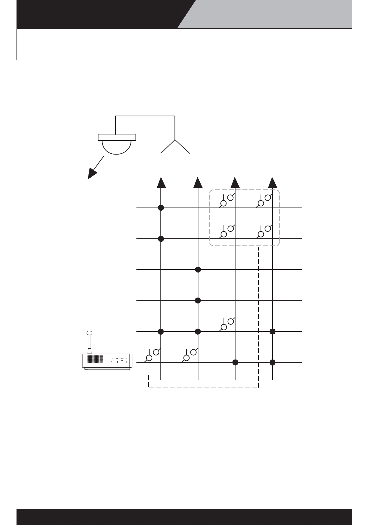
4.Arrange the Transmitter/Receiver unit in such a way that individual conference units
can communicate with more than one Transmitter/Receiver unit.
As shown in a drawing, when a speaker in the front row talks while standing up, the infrared
reception could be interrupted. If the conference unit is made to communicate with two or more
Transmitter/Receiver units, such interruption won’t happen.
Note:
Enabling the conference unit to communicate with more than one Transmitter/Receiver units
greatly stabilizes operation. It also reduces the compandor noise that happens when the
conference unit is used at a location that is just barely within the coverage range.
7
-2
Page 18

CAUTIONS IN INSTALLING TS-800/900 SERIES
Cautions in installing the conference unit
Make sure that the infrared signal receiver of the unit is not exposed to direct sunlight.
If direct sunlight hits the infrared signal receiver, the reception may be interrupted.
Curtain
Sunlight
Window
Note:
In a situation shown in the drawing above, the problem can generally be resolved by shading
direct sunlight with curtains or blinds.
7
-3
Page 19

TRANSMITTER/RECEIVER UNIT
TS-800/900 SERIES
Transmitter/Receiver unit arrangement example
The maximum straight-line distance permissible for communication between the
Transmitter/Receiver unit and the conference unit is 7 meters.
Thus, the area range the Transmitter/Receiver unit
can cover varies depending on the height from
the conference unit to the ceiling. Arrange
Transmitter/Receiver units in such a way that the
units' coverage ranges overlap, so that all
conference units are included in the service area.
Infrared transmitter/receiver
6m
9m9m
Area for installing
the Chairman/Delegate units
Conference room with the area of 30 x 30 meters
When the ceiling height is less than 7 meters, if the
units are arranged at intervals of 9 meters as
shown in the figure, a service area covering every
corner of the room can be secured.
*Choose the appropriate transmitter/receiver unit according to the
ceiling height.
Conference room using a round table
In a situation where all Chairman and Delegate
units are arranged on a round table and infrared
signals are not obstructed, a single
Transmitter/Receiver unit may completely cover
conference communications.
However, it is recommended that two or more
Transmitter/Receiver units be installed to prevent
communication interruptions.
6m
6m
Infrared transmitter/receiver
10 – 15 m
10 – 15 m
9m
9m
Area for installing
the Chairman/Delegate units
6m
Note:
In the case of a 30-by-30-meter room shown in the drawing, the units are arranged to provide more
than ample overlap of coverage areas. Arrangement like this, if it can be afforded, provides highly
stable communication environment. However, by arranging units to suit the usage (refer to
“Transmitter/Receiver unit arrangements according to the room size” below), it is possible to reduce the
number of Transmitter/Receiver units used.
8
Page 20

TRANSMITTER/RECEIVER UNIT
TS-800/900 SERIES
Transmitter/Receiver unit arrangements
according to the seating style
When the same number of Transmitter/Receiver units is installed in rooms with the same size, the
arrangement of the units varies depending on the seat layout.
The drawings below represent ideal Transmitter/Receiver unit arrangements for roundtable seating and
parliamentary seating styles.
Arrangement for the roundtable seating style
In this case, placing the Transmitter/Receiver units
evenly inside the seating area enables all conference
units to communicate with both Transmitter/Receiver
units.
Arrangement for the parliamentary seating style
In this case, if the Transmitter/Receiver units are
arranged evenly, as is done for the roundtable
seating style, the Transmitter/Receiver unit at the rear
can communicate with only a smaller number of
conference units (because infrared signals from
conference units travel only in the forward direction).
For efficient utilization of the coverage area, it is
effective to place the Transmitter/Receiver units
toward the front of the conference units.
10000
10000
TS-802TS-802
TS-802TS-802
6000
TS-802TS-802
TS-802TS-802
6000
TS-801
TS-802
TS-802TS-802
TS-802
TS-802TS-802
TS-802
TS-802TS-802
TS-802TS-802TS-802TS-802
9
TS-802 TS-802TS-802
Page 21

TRANSMITTER/RECEIVER UNIT
TS-800/900 SERIES
Transmitter/Receiver unit arrangements
according to the room size
The drawings below show examples of the Transmitter/Receiver unit placement for different room sizes
for both roundtable and parliamentary seating styles.
Roundtable seating
6000
TS-802TS-802
TS-802TS-802TS-802
TS-802TS-802TS-802
10000
TS-802TS-802
10m x 6m
Parliamentary seating
15000
10000
TS-802TS-801TS-802
TS-802TS-802 TS-802TS-802TS-802
TS-802
TS-802TS-802TS-802
15m x 10m
TS-802
TS-802TS-802 TS-802TS-802TS-802
25000
15000
TS-802TS-802TS-802TS-802TS-802TS-802
TS-802TS-802TS-801TS-802TS-801TS-802 TS-802TS-801TS-802TS-801TS-802TS-801
TS-802TS-802TS-802TS-802TS-802TS-802 TS-802TS-802TS-802TS-802TS-802TS-802
TS-802TS-802TS-802TS-802TS-802TS-802
25m x 15m
10000
10m x 6m
6000
TS-802TS-802 TS-802
TS-802TS-802 TS-802
TS-802TS-802 TS-802
TS-802TS-802 TS-802
TS-801
TS-802 TS-802 TS-802 TS-802 TS-802
TS-802 TS-802 TS-802 TS-802 TS-802
15000
TS-802 TS-802 TS-802 TS-802 TS-802
TS-802 TS-802 TS-802 TS-802 TS-802
TS-802 TS-802 TS-802 TS-802 TS-802
10000
TS-801
15m x 10m
15000
TS-801
TS-801 TS-801
TS-802 TS-802 TS-802 TS-802 TS-802 TS-802 TS-802
TS-802 TS-802 TS-802 TS-802 TS-802 TS-802 TS-802
TS-802 TS-802 TS-802 TS-802 TS-802 TS-802 TS-802
TS-802 TS-802 TS-802 TS-802 TS-802 TS-802 TS-802
25000
TS-802 TS-802 TS-802 TS-802 TS-802 TS-802 TS-802
TS-802 TS-802 TS-802 TS-802 TS-802 TS-802 TS-802
TS-802 TS-802 TS-802 TS-802 TS-802 TS-802 TS-802
TS-802 TS-802 TS-802 TS-802 TS-802 TS-802 TS-802
TS-802 TS-802 TS-802 TS-802 TS-802 TS-802 TS-802
TS-801TS-801 TS-801 TS-801
25m x 15m
10
Page 22

TRANSMITTER/RECEIVER UNIT
TS-800/900 SERIES
Wiring between the Transmitter/Receiver unit
and the Central unit
1. Note on wiring
When two or more Transmitter/Receiver units receive infrared signals from the conference unit,
the signal reception level increases if input signals to each Transmitter/Receiver unit are in phase.
If not in phase, the reception level may decrease. To avoid such a situation, the length of the
cables between the Central unit and each Transmitter/Receiver unit used in the same space
must be identical.
Infrared transmitter/receiver Distributor
L
L
M1
L
L
M0
Central unit
L
L
N0 N1
M0
M1
L+M0+N0 = M1+N0 = N1
2. When a distributor is used
When using a distributor (YW-1022, YW-1024), do not connect more than two distributors in series.
Connecting three or more distributors increases high-frequency signal loss, and could result in
system malfunction.
It is possible to mix Transmitter/Receiver units that are not connected to any distributor, those
connected to 1 distributor, and those connected to 2 distributors in the same system.
[Example 1]
N
N
Central unit
N
N
Infrared transmitter/receiver
All cables for "N" must be identical in length
when the Transmitter/Receiver units are installed
in the same space.
11
-1
Page 23

TRANSMITTER/RECEIVER UNIT
TS-800/900 SERIES
Wiring between the Transmitter/Receiver unit
and the Central unit
[Example 2]
Infrared transmitter/receiver Distributor
When installing in the same space.
L
L
L
L
L
L
L
L
• All "L" cables must be identical in length.
• All "M" cables must be identical in length.
M
M
L
L
[Example 3]
Conference room A
L1
L1
Distributor
L1
L1
L
L
Central unit
L
L
N
M1
M
M
Note
To facilitate the unification of coaxial cables used in
different connections into the same length, it is highly
L
L
recommended that wiring from the Central unit to the
distributor mounted in a ceiling be performed with a
single cable. For other ceiling wiring, using pre-cut
coaxial cables of a slightly longer length will facilitate
making all connections the same length.
Conference room B
L0
L0
M0
M0
L0
L0
*Connectable up to 16 units (TS-905) and up to 12units (TS-907)
When installing in multiple rooms
where the light is shut off,
coaxial cables used in different rooms
L0
L0
L0
L0
need not be matched to the same length.
• All L0 cables are the same length.
• All L1 cables are the same length.
• All M0 cables are the same length.
• L0 and L1 cables need not be
the same, since they are used in
different rooms.
• M0 and M1 cables need not be the
same length, since they are used in
different rooms.
N
Central unit
11
Infrared transmitter/receiver
-1
Page 24

TRANSMITTER/RECEIVER UNIT
TS-800/900 SERIES
Wiring Design Exsamples
(Finding the maximum cable length between the Central Unit and the Infrared Transmitter/Receiver Unit)
Values calculated here are given only as guidelines, since they can vary depending on
ambient building conditions and the Infrared Transmitter/Receiver unit.
Conditions for Finding Cable Length
To obtain the coaxial cable maximum length, calculate the cable length on each condition. The shorter length
of the two results is the required maximum length.
(1) Maximum allowable cable loss: 20 dB (Total cable and distributor loss)
(2) Maximum allowable cable DC voltage drop: 5 V
Values necessary for each calculation are as follows.
Values necessary for calculating the maximum allowable cable loss
(1) 2-branch distributor (YW-1022) loss: 4.5 dB
(2) 4-branch distributor (YW-1024) loss: 8.5 dB
(3) Coaxial cable loss per 100 m (table shown below)
RG-59/U
RG-6/U
RG-11/U
Note: The values in the table above are losses at 10 MHz.
Values necessary for calculating the cable voltage drop
(1) Operating current per Infrared Transmitter/Receiver unit: 0.1 A
(2) Distributor resistance loss: 0 Ω
(3) Coaxial cable loop resistance per 100 m (table shown below)
3.3 dB
2.7 dB
2.0 dB
RG-59/U
RG-6/U
RG-11/U
Note: The values in the table above are losses at 10 MHz.
Note: Coaxial cable loss and loop resistance values used here are based on our investigation.
16.82 Ω
12.82 Ω
2.4 Ω
12
-1
Page 25

TRANSMITTER/RECEIVER UNIT
TS-800/900 SERIES
Wiring Design Exsamples
Computational Equation
Finding the wireing loss
Requirement: Total loss & 20 dB
Cable loss = (Length/100) × Loss per 100 m
Total loss = Cable 1 loss + Cable 2 loss + Cable 3 loss + Distributor 1 loss + Distributor 2 loss
Central Unit
Coaxial cable 1
Coaxial cable 1 loss
Finding the wiring voltage drop
Requirement: Total loss & 5 V
Cable voltage drop = (Length/100) × Loop resistance per 100 m × Current
Cable current = Number of the conneceted Infrared Transmitter/Receiver units × 0.1 (TS-905) or 0.13 (TS-907)
Total voltage drop = Voltage drop 1 + Voltage drop 2 + Voltage drop 3
Central unit
Coaxial cable 1
Distributor 1
Distributor
Coaxial cable 2
Coaxial cable 2 loss
Coaxial cable 2
Distributor 2
Distributor
Transmitter/Receiver
Coaxial cable 3
Coaxial cable 3 loss
Transmitter/Receiver
Coaxial cable 3
unit
unit
Current 1
Voltage drop 1
Note: For the coaxial cable required to carry a large current, use a cable of low loop resistance type.
[Finding the cable current]
Cable current = Number of the conneceted Infrared Transmitter/Receiver units × 0.1 (TS-905) or 0.13 (TS-907)
The cable current changes when the Distributor is used, as shown below.
Central unit Central unit
0.1 A 0.2 A
Infrared
Transmitter/Receiver
units TS-905
Current 2
Voltage drop 2
Current 3
Voltage drop 3
Distributor 1
Infrared
Transmitter/Receiver
units TS-905
0.1 A
0.1 A
12
-2
Page 26

TRANSMITTER/RECEIVER UNIT
TS-800/900 SERIES
Wiring Design Exsamples
Design Examples
Example 1: When installing 4 TS-905 Infrared Transmitter/Receiver units using 4 coaxial cables
reaching from the Central unit:
Central unit Transmitter/Receiver units
L
1) Finding the maximum cable length using maximum allowable cable losses
Assuming that the type of coaxial cable used is RG-59/U,
Maximum cable length L = (Coaxial cable loss / its cable loss per 100 m )
= (20 dB / 3.3 dB) x 100 m
= 606 m
The following table shows the maximum allowable cable length for each type of coaxial cable.
RG-59/U
RG-6/U
RG-11/U
2) Finding the maximum cable length using voltage drop
Since one Infrared Transmitter/Receiver unit is connected per coaxial cable, the current that flows through
each coaxial cable is 0.1 A.
Assuming that the type of coaxial cable used is RG-59/U,
Maximum length L = { (Voltage drop 1 / Current 1) / Coaxial cable loop resistance 1 for 100 m }
606 m
740 m
1000 m
= { (5 V / 0.1 A) / 16.82 Ω } x 100 m
= 297 m
The following table shows the maximum allowable cable length for each type of coaxial cable.
RG-59/U
RG-6/U
RG-11/U
The table below shows the required maximum cable length for the example 1, the shorter length of the
calculation results (1) and (2) above.
RG-59/U
RG-6/U
RG-11/U
297 m
390 m
2083 m
297 m
390 m
1000 m
12
-3
Page 27

TRANSMITTER/RECEIVER UNIT
TS-800/900 SERIES
Wiring Design Exsamples
Example 2: When installing 4 TS-905 Infrared Transmitter/Receiver units using 4 coaxial cables
reaching from the Central unit (one 4-branch distributor connected):
Condition: Cable length between the Distributor and the Infrared Transmitter/Receiver unit is assumed to be
50 meters.
Central unit
L1
1) Finding the maximum cable length using maximum allowable cable losses
Assuming that RG-59/U coaxial cable is used between the Distributor and the Infrared
Transmitter/Receiver unit, the cable loss between the two is calculated by the following equation:
Cable loss = 3.3 dB x (50 m / 100 m) = 1.65 dB
Since the Distributor's internal loss is 8.5 dB, the maximum allowable loss between the Central unit and the
Distributor becomes 9.85 dB (20 dB – 1.65 dB – 8.5 dB).
Distributor
50 m
L
Infrared Transmitter/Receiver units
TS-905
When RG-6/U coaxial cable is used between the Central unit and the Distributor, the length L1 between
the two is,
L1 = (Coaxial cable loss / its cable loss per 100 m )
= (9.85 dB / 2.7 dB) x 100 m
= 364 m
Maximum cable length L between the Central unit and the Infrared Transmitter/Receiver unit is
calculated by the following equation:
L= L1 + 50 m
= 364 m + 50 m
= 414 m
Similarly calculated for other types of coaxial cables, the maximum cable length between the Central unit
and the Infrared Transmitter/Receiver unit is found in the following table.
RG-59/U
RG-6/U
RG-11/U
348 m
414 m
542 m
12
-4
Page 28

TRANSMITTER/RECEIVER UNIT
TS-800/900 SERIES
Wiring Design Exsamples
2) Finding the maximum cable length using voltage drop
The current flowing from the Distributor into each coaxial cable connected to the TS-905 Infrared
Transmitter/Receiver unit is 0.1 A, since the number of Infrared Transmitter/Receiver units connected to
each coaxial cable is 1.
Assuming that RG-59/U coaxial cable is used, the voltage drop between the Distributor and the Infrared
Transmitter/Receiver unit is calculated by the following equation:
Voltage drop = 16.82 Ω x (50 m / 100 m) x 0.1 A
= 0.841 V
A remaining voltage of 4.159 V (5 V – 0.841 V) is the maximum allowable voltage drop between the
Central unit and the Distributor. The current that flows between the two is 0.4 A.
When RG-6/U coaxial cable is used between the Central unit and the Distributor, the cable length L1
between the two is,
L1 = { (Voltage drop 1 / Current 1) / Coaxial cable loop resistance 1 per 100 m }
= { (4.159 V / 0.4 A) / 12.82 Ω } x 100 m
= 81 m
Maximum cable length L between the Central unit and the Infrared Transmitter/Receiver unit is
calculated by the following equation:
L= L1 + 50 m
= 81 m + 50 m
= 131 m
Similarly calculated for other types of coaxial cables, the maximum cable length between the Central unit
and the Infrared Transmitter/Receiver unit is found in the following table.
RG-59/U
RG-6/U
RG-11/U
The table below shows the required maximum cable length for the example 2, the shorter length of the
calculation results (1) and (2) above.
111 m
131 m
483 m
RG-59/U
RG-6/U
RG-11/U
111 m
131 m
483 m
12
-5
Page 29

TRANSMITTER/RECEIVER UNIT
TS-800/900 SERIES
Wiring Design Exsamples
Example 3: When installing 4 TS-905 Infrared Transmitter/Receiver units using 4 coaxial cables
reaching from the Central unit (four 4-branch distributors connected):
Condition: Cable length between the Distributor and the TS-905 Infrared Transmitter/Receiver unit is
assumed to be 50 meters.
Central unit
L1
Distributor
1
4
L
Infrared Transmitter/Receiver units
TS-905
50 m
The equation and maximum cable length in this example are the same as those in Example 2 in the previous
section; "4 TS--905 Infrared Transmitter/Receiver units using 1 coaxial cable from the Central Unit
(one 4-branch distributor connected)."
12
-6
Page 30

TRANSMITTER/RECEIVER UNIT
TS-800/900 SERIES
Wiring Design Exsamples
Example 4: When installing 16 TS-905 Infrared Transmitter/Receiver units using 1 coaxial cable
reaching from the Central unit (five 4-branch distributors connected):
Condition: Length between the Distributor 2 and the TS-905 Infrared Transmitter/Receiver unit is assumed to
1) Finding the maximum length using maximum allowable cable losses
Assuming that RG-59/U coaxial cable is used, the cable loss between the Distributor 2 and the Infrared
Transmitter/Receiver unit is calculated by the following equation:
Assuming that RG-6/U coaxial cable is used, the cable loss between the Distributor 1 and Distributor 2 is
calculated by the following equation:
be 50 meters, and the length between Distributor 1 and Distributor 2 10 meters.
Infrared Transmitter/Receiver units
Distributor 2
2
Distributor 1Central unit
1
L1
Cable loss = 3.3 dB x (50 m / 100 m) = 1.65 dB
Cable loss = 2.7 dB x (10 m / 100 m) = 0.27 dB
5
L
50 m10 m
TS-905
Because of the 2 serially-connected 4-branch distributors, their loss is 17 dB (8.5 dB + 8.5 dB), which is
added to the above cable loss, causing a total loss of 18.92 dB (1.65 dB + 0.27 dB + 17 dB). Therefore, the
maximum allowable cable loss between the Central unit and the Distributor 1 is calculated to be 1.08 dB
(20 dB – 18.92 dB).
• Assuming that RG-11/U coaxial cable is used, L1 between the Central unit and the Distributor 1 is
calculated by the following equation:
L1 = (Coaxial cable loss / its cable loss per 100 m)
= (1.08 dB / 2 dB) x 100 m
= 54 m
Maximum cable length L (Length between the Central unit and the Infrared Transmitter/Receiver unit)
= 54 m + 10 m + 50 m = 114 m
• Assuming that RG-6/U coaxial cable is used, L1 between the Central unit and the Distributor 1 is
calculated by the following equation:
L1 = (Coaxial cable loss / its cable loss per 100 m)
= (1.08 dB / 2.7 dB) x 100 m
= 40 m
Maximum cable length L (Length between the Central unit and the Infrared Transmitter/Receiver unit)
= 40 m + 10 m + 50 m = 100 m
Similarly calculated for other types of coaxial cables, the maximum cable
length between the Central unit and the Infrared Transmitter/Receiver unit
is found in the table.
RG-59/U
RG-6/U
RG-11/U
92 m
100 m
114 m
12
-7
Page 31

TRANSMITTER/RECEIVER UNIT
TS-800/900 SERIES
Wiring Design Exsamples
2) Finding the maximum cable length using voltage drop
The current flowing from the Distributor 2 into each coaxial cable connected to an Infrared
Transmitter/Receiver unit is 0.1 A, since the number of Infrared Transmitter/Receiver units connected to
each coaxial cable is 1.
Assuming that RG-59/U coaxial cable is used, the voltage drop between the Distributor 2 and the Infrared
Transmitter/Receiver unit is calculated by the following equation:
Voltage drop = 16.82 Ω x (50 m / 100 m) x 0.1 A
= 0.841 V
When RG-6/U type coaxial cable is used, since the current flowing into each coaxial cable between
Distributor 1 and Distributor 2 is 0.4 A, the voltage drop between the two is calculated by the following
equation:
Voltage drop 2 = 12.82 Ω x (10 m / 100 m) x 0.4 A
= 0.513 V
Voltage drop 1 + Voltage drop 2 = 1.354 V
A remaining voltage of 3.646 V (5 V – 1.354 V) is the maximum allowable voltage drop between the
Central unit and the Distributor 1. The current that flows between the two is 1.6 A.
• Assuming that RG-11/U coaxial cable is used, L1 between the Central unit and the Distributor 1 is
calculated by the following equation:
L1 = { (Voltage drop 1 / Current 1) / Coaxial cable loop resistance 1 per 100 m }
= { (3.646 V / 1.6 A) / 2.4 Ω } x 100 m
= 94 m
Maxim cable length L (Length between the Central unit and the Infrared Transmitter/Receiver unit)
= 94 m + 10 m + 50 m = 154 m
• Assuming that RG-6/U coaxial cable is used, L1 between the Central unit and the Distributor 1 is
calculated by the following equation:
L1 = { (Voltage drop 1 / Current 1) / Coaxial cable loop resistance 1 per 100 m }
= { (3.646 V / 1.6 A) / 12.82 Ω } x 100 m
= 17 m
Maxim cable length L (Length between the Central unit and the Infrared Transmitter/Receiver unit)
= 17 m + 10 m + 50 m = 77 m
Similarly calculated for other types of coaxial cables, the maximum cable length between the Central unit
and the Infrared Transmitter/Receiver unit is found in the following table.
RG-59/U
RG-6/U
RG-11/U
The table below shows the required maximum cable length for the example 4, the shorter length of the
calculation results (1) and (2) above.
RG-59/U
RG-6/U
RG-11/U
73 m
77 m
154 m
73 m
77 m
114 m
12
-8
Page 32

TRANSMITTER/RECEIVER UNIT
TS-800/900 SERIES
Notes on installation (summary)
Notes on installation (summary)
• The coverage area of infrared communication varies depending on the type of the
Transmitter/Receiver unit used and ceiling height. (see page 5-1)
• The TS-905 works for ceiling heights of more than 2.5 meters and less than 5 meters,
while the TS-907 works for heights of between 5.0 meters and 7.0 meters. In view of the
Transmitter/Receiver unit’s performance capability, infrared communication becomes difficult
if the ceiling height exceeds 7 meters.
• In mounting the Transmitter/Receiver unit, consideration should be given to the direction
in which infrared signals from the conference unit travel.
• Do not install the Infrared Conference System in the same space where a plasma display or
an infrared LAN system is in use.
• Be careful of downlights and spotlights that give off a large amount of light.
• Install the Transmitter/Receiver unit away from windows, lighting equipment, and obstacles.
• The effect of sunlight can be avoided by the use of curtains or blinds.
• Use appropriate numbers and arrangement of Transmitter/Receiver units, so that the
conference unit can communicate with two ore more Transmitter/Receiver units.
• The more Transmitter/Receiver units are used, the more stabilized communications the System
can provide.
• Be sure to make all cables between the Central unit and the Transmitter/Receiver unit identical
in length.
• When a distributor is used, make the length of all cables coming out from the distributor
identical. This minimizes unnecessary wiring.
• After wiring design is completed, the cable loss and voltage drop must be calculated.
13
Page 33

USEFUL-TO-KNOW FUNCTIONS
Useful-to-know functions
(1) Installation confirmation check
Installation status of conference units can be checked from the Central unit.
1.Switch on the power to the Central unit while holding
down its Voting Start/End button.
The Central unit's Battery indicator lights up, placing
the unit in the installation confirmation mode.
The microphone indicator on the conference unit
flashes.
The Voting Result monitors (1-3) of the Central unit flash,
with all displays showing [0].
TS-800/900 SERIES
POWER
Lights
BATTERYDATA
Flashes
Battery indicator
VOTING
START/END3
21
Voting result display
Conference units transmit an acknowledgment signal
one after another.
Upon receipt of the acknowledgment signal, the
Central unit sends out a response confirmation signal.
The microphone indicator on the conference unit that
has received the confirmation signal changes from
flashing to a steady glow.
The Voting Result monitors (1-3) provide a flashing
indication of "the number of Chairman units installed,"
"the number of Delegate units installed," and
"the total number of conference units installed,"
respectively.
2.After confirming the indication, press the Voting
Start/End button for 1 second.
The Central unit's Battery indicator and
Voting Result monitors (1-3) turn off. The microphone
indicator on the conference unit also goes out,
terminating the installation confirmation mode and
bringing the system back to the normal operation state.
POWER
Number of installed
Chairman units
Number of installed Delegate units
Flashes
POWER
Lights
BATTERYDATA
VOTING
VOTING
321
START/END3
21
Total number of installed
Chairman and Delegate units
Extinguished
BATTERYDATA
VOTING
START/END3
21
Extinguished
Note:
This function is also available on the TS-800 Series. In the case of the TS-800, switch on the
power while holding down the TEST button. Indication of the numbers of installed units is not
possible with the TS-800 Series.
14
-1
Page 34

USEFUL-TO-KNOW FUNCTIONS
TS-800/900 SERIES
Useful-to-know functions
(2) Monitor-dedicated unit
A conference unit can be used exclusively as a monitor by assigning the ID number "00" to
the unit. (In this situation, the unit cannot be used for speech)
Because the monitor-dedicated unit is free from the restrictions on the maximum number of
connectable conference units (96 units for the 900 Series and 64 for the 800 Series), it is possible
to use any number of monitor-dedicated units.
(3) Initiation of voting from the Chairman unit
Flip the Voting Activation DIP switch on the bottom of the Chairman unit to ON. The Chairman unit
TS-901 whose Voting Activation switch is set to the ON position can initiate voting.
Voting buttons 1 and 2 can be held down simultaneously.
(4) Priority speech from the Chairman unit during v oting
Chairman can make a speech using the priority speech function of the Chairman unit even while
voting is in progress.
This function can be used to announce the termination of voting or to urge participants to vote.
(5) Connection to the TV conference system using the mix-cut capability of
AUX3 (this feature is available onl y on the TS-900 Series)
When connecting to the TV conference system, installation and connection as shown below
allows the unit to function as a terminal, which delivers clear sound unmarred by acoustic
feedback.
AUX 3 (set to CUT)
LINE OUT
Central unit
TS-900
When AUX 3 is set to CUT, sound coming from AUX3 is not outputted to LINE OUT. As a
result, voice of the speaker is prevented from re-entering the speaker’s unit, enabling
conference sessions with excellent voice clarity.
AUDIO OUT
AUDIO IN
14
-2
Page 35

COMPARISON OF FEATURES TS-800/900 SERIES
Comparison of features between the TS-800/900
and TS-700 series
TS-800/900 TS-700
Number of simultaneous speaker units 1/2/4 1/2/4/6
Auto Mic-off time setting Fixed at 30 seconds 20 seconds/40 seconds
Speech system First-in-first-out/Last-in-first-out/
Last-in-first-out after 2nd unit First-in-firs out” mode only
Operation during priority speech-1: After completion of the priority After completion of the priority
when the Chairman unit interrupts speech, the interrupted unit speech, the interrupted unit
other units to make a priority speech resumes the mode in operation is terminated.
prior to initiation of the priority
speech..
Operation during priority speech-2: Chime-tone activation/ Individual setting of each Chairman
chime tone activation/deactivation deactivation at the time of the unit is not possible.
at the time of the priority speech priority speech can be set
for each Chairman unit.
Operation during priority speech-3: “Restore “or “Reset” can be “Reset” only.
Operation of the interrupted unit after selected for each
completion of the priority speech Chairman unit.
Headphone jack on the terminal 1 on either side (total of 2) 1 on the rear panel (for REC)
Microphone length Selectable between No t selectable
Standard (TS-903) and
Long (TS-904)
Microphone connection jack 4P Canon connector
15
Page 36

SPECIFICATIONS TS-800
TS-800 CENTRAL UNIT
The TS-800 is a Central unit of the Infrared Conference system. Since the system is cordless, it can be easily
installed and removed based on a free layout.
Connecting the TS-800 to the Transmitter/Receiver units permits control of the conference units.
It features control function from a PC (The control software is not attached.), and installation confirmation function
that confirms the connection status for the Transmitter/Receiver units and installation status for the conference units.
With the use of an optional rack mounting bracket, it can be mounted in an EIA Standard equipment rack (4 unit
size).
* 0dB = 1V
Power Source
Power Consumption
Input
Output
Number of Connectable
Chairman/Delegate Units
Number of Connectable
Infrared T ransmitter/Receiv er Units
Infrared T ransmitter/
Receiver I/O Terminal
External Control Terminal
LED Indicator
Function Switch
Operating T emperature
Finish
Weight
Accessory
Option
100 – 240 V AC, 50/60 Hz (supplied from AC adapter (accessory))
72 W
MIC: –60 dB*, 600 Ω, unbalanced, phone jac k
AUX: –20 dB*, 10 kΩ, unbalanced, phone jack
REC: –20 dB*, 10 kΩ, unbalanced, phone jac k, RCA pin jac k
HEADPHONE: Mini jack
64 units
4 units (up to 16 units by using four distributors)
4 BNC jacks
D-sub connector (9 P, male)
Audio signal receiving indicators 1 – 4 CH, Data signal receiving indicator, External control
priority indicator, External control communication indicator, Power indicator, Battery indicator
(flashes when a Chairman/Delegate unit's battery nears complete discharge)
Simultaneous speaker No. setting switch: 1/2/4
Mic-off setting switch: TIME OUT ON/OFF
Speech priority selector switch: A/B/C
(A: First-in-first-out priority, B: Last-in-first-out priority, C: Fix ed for the first unit,
and last-infirst-out for the subsequent units)
0°C to +40°C
Panel: Surface-treated steel plate , g ray metallic, paint, semi-gloss
2.7 kg
AC adapter (Cord length: 1.8 m DC cord, and 2 m detachable A C cord) × 1
Rack mounting bracket: MB-TS900
[Top]
[Front]
359
16
118.8179.8
-1
140
20
[Side]
70
21.2
117
138.2
100.3
Figure of the unit installed
(118.8)
Unit: mm
Page 37

SPECIFICATIONS TS-801
TS-801 CHAIRMAN UNIT
The TS-801 is a Chairman unit of the Infrared Conference system. Since the system is cordless, it can be easily
installed and removed.
The Chairman unit features a priority speech key which allows it to take precedence over the TS-802 Delegate units
(optional) when speaking. It can be operated on either the AD-0910 AC adapter (optional) or the BP-900 lithium-ion
battery (optional). It is equipped with a remaining battery indicator. Two types of dedicated microphones are made
available for the TS-801 as optional products: the TS-903 standard type and the TS-904 long type.
Power Source
Current Consumption
Infrared Emittery/Detector
Wavelength
Modulation Method
Carrier Frequency
Acceptance Angle
Emission Angle
Covering Range
Input
Output
LED Indicator
Battery Life
Operating T emperature
Finish
Dimensions
Weight
Option
7.4 V DC (battery), 9 V DC (A C adapter)
(supplied from BP-900 battery (option) or AD-0910 AC adapter (option))
Max. 270mA
870 nm (AM: Brightness modulation)
Frequency modulation
Transmission: Audio channel 1: 7.35 MHz
Audio channel 2: 8.10 MHz
Audio channel 3: 8.55 MHz
Audio channel 4: 9.15 MHz
Control channel: 6.45 MHz
Reception: Audio channel: 1.95 MHz
Vertical: 90°, Horizontal: 120°
Vertical: 90°, Horizontal: 120°
7 m (radius)Microphone terminal: Combined type of XLR-4-31(dedicated for connecting the
optional TS-903 or TS-904)
Monitor speaker: 8Ω, 0.2 W
Headphone: Mini jack × 2
Speech indicator (flasher when the unit is out of communications range), Po wer indicator
(flashes when the unit is out of communications range or when the battery level is low)
Approx. 10 hours (when the fully-charged BP-900 battery is used with “During Speech” to
“Standby”h ratio of 1 : 2)
0°C to +40°C
Top panel: ABS resin, gra y metallic , paint, semi-matte
210 (W) × 65.9 (H) × 152 (D) mm
630 g
Microphone: TS-903, TS-904 (Select either one.), Lithium-ion battery: BP-900,
AC adapter: AD-0910
210
16
15265.9
-2
Microphone
(option)
Unit: mm
Page 38

SPECIFICATIONS TS-802
TS-802 DELEGATE UNIT
The TS-802 is a Delegate unit of the Infrared Conference system. Since the system is cordless, it can be easily
installed and removed.
It can be operated on either the AD-0910 AC adapter (optional) or the BP-900 lithium-ion battery (optional). It is
equipped with a remaining battery indicator. Two types of dedicated microphones are made available for the
TS-802 as optional products: the TS-903 standard type and the TS-904 long type.
Power Source
Current Consumption
Infrared Emittery/Detector
Wavelength
Modulation Method
Carrier Frequency
Acceptance Angle
Emission Angle
Covering Range
Input
Output
LED Indicator
Battery Life
Operating T emperature
Finish
Dimensions
Weight
Option
7.4 V DC (battery), 9 V DC (A C adapter)
(supplied from BP-900 battery (option) or AD-0910 AC adapter (option))
Max. 270mA
870 nm (AM: Brightness modulation)
Frequency modulation
Transmission: Audio channel 1: 7.35 MHz
Audio channel 2: 8.10 MHz
Audio channel 3: 8.55 MHz
Audio channel 4: 9.15 MHz
Control channel: 6.45 MHz
Reception: Audio channel: 1.95 MHz
Vertical: 90°, Horizontal: 120°
Vertical: 90°, Horizontal: 120°
7 m (radius)Microphone terminal: Combined type of XLR-4-31(dedicated for connecting the
optional TS-903 or TS-904)
Monitor speaker: 8Ω, 0.2 W
Headphone: Mini jack × 2
Speech indicator (flasher when the unit is out of communications range), Po wer indicator
(flashes when the unit is out of communications range or when the battery level is low)
Approx. 10 hours (when the fully-charged BP-900 battery is used with “During Speech” to
“Standby”h ratio of 1 : 2)
0°C to +40°C
Top panel: ABS resin, gra y metallic , paint, semi-matte
210 (W) × 65.9 (H) × 152 (D) mm
630 g
Microphone: TS-903, TS-904 (Select either one.), Lithium-ion battery: BP-900,
AC adapter: AD-0910
210
16
152
65.9
-3
Microphone
(option)
Unit: mm
Page 39

SPECIFICATIONS TS-900
TS-900 CENTRAL UNIT
The TS-900 is a Central unit of the Infrared Conference system. Since the system is cordless, it can be easily
installed and removed based on a free layout.
Connecting the TS-900 to the Transmitter/Receiver units permits control of the conference units.
It features control function from a PC (The control software is not attached.), installation confirmation function that
confirms the connection status for the Transmitter/Receiver units and installation status for the conference units, and
voting function that computes and displays the voting result. Since two speech outputs are provided (Main and Sub
channels), it is ideal for use in simultaneous interpreting conference.
With the use of an optional rack mounting bracket, it can be mounted in an EIA Standard equipment rack (4 unit size).
* 0dB = 1V
Power Source
Power Consumption
Input
Output
Number of Connectable
Chairman/Delegate Units
Number of Connectable
Infrared T ransmitter/Receiv er Units
Infrared T ransmitter/
Receiver I/O Terminal
External Control Terminal
LED Indicator
Function Switch
Microphone Mix/Cut Switch (for the
Base Language)
Microphone Mix/CutSwitch (for the
TranslationLanguage)
AUX 3 Mixing Select Switch
Operating T emperature
Finish
Weight
Accessory
Option
100 – 240 V AC, 50/60 Hz (supplied from AC adapter (accessory))
72 W
MIC 1 (Base Language): –60 dB*, 600Ω, unbalanced, phone jac k
MIC 2 (Translation Language): –60 dB*, 600Ω, unbalanced, phone jack
AUX 1 (Base Language): –20 dB*, 10 kΩ, unbalanced, phone jack
AUX 2 (Translation Language): –20 dB*, 10 kΩ, unbalanced, phone jack
AUX 3 (Base and Translation Language): –20 dB*, 10 kΩ, unbalanced, phone jack
LINE: –20 dB*, 10 kΩ, unbalanced, phone jac k
REC: –20 dB*, 10 kΩ, unbalanced, phone jac k, RCA pin jac k
HEADPHONE: Mini jack
96 units
4 units (up to 16 units by using four distributors)
4 BNC jacks
D-sub connector (9 P, male)
Voting result indicators 1 – 3 (7-segment LED, doub ledigit number), Audio signal receiving
indicators 1 – 4CH, Data signal receiving indicator, External control priority indicator, External
control communication indicator, Power indicator , Battery indicator (flashes when a
Chairman/Delegate unit's battery nears complete discharge)
Simultaneous speaker No. setting switch: 1/2/4
Mic-off setting switch: TIME OUT ON/OFF
Speech priority selector switch: A/B/C
(A: First-in-first-out priority, B: Last-in-first-out priority, C: Fix ed for the first unit, and
last-infirst-out for the subsequent units)
MIC/CUT (Mix): Chairman/Delegate units + MIC 1 + AUX 1 + AUX 3 ➞Base Language
(Cut): MIC 1 + A UX 1 + AUX 3 ➞Base Language
MIC/CUT (Mix): Chairman/Delegate units + MIC 2 + AUX 2 + AUX 3 ➞Translation Language
(Cut): MIC 2 + A UX 2 + AUX 3 ➞Translation Language
MIC/CUT (Mix): A UX 3 input is relayed to the line output.
(Cut): A UX 3 input is not relayed to the line output.
0°C to +40°C
Panel: Surface-treated steel plate , g ray metallic, paint, semi-gloss
2.8 kg
AC adapter (Cord length: 1.8 m DC cord, and 2 m detachable AC cord) × 1
Rack mounting bracket: MB-TS900
[Top]
[Front]
359
16
118.8179.8
-4
140
20
[Side]
70
21.2
117
138.2
100.3
Figure of the unit installed
(118.8)
Unit: mm
Page 40

SPECIFICATIONS TS-901
TS-901 CHAIRMAN UNIT
The TS-901 is a Chairman unit of the Infrared Conference system. Since the system is cordless, it can be easily
installed and removed.
The Chairman unit features a priority speech key which allows it to take precedence over the TS-902 Delegate units
(optional) when speaking. It can be operated on either the AD-0910 AC adapter (optional) or the BP-900 lithium-ion
battery (optional). It is equipped with a remaining battery indicator. Two types of dedicated microphones are made
available for the TS-901 as optional products: the TS-903 standard type and the TS-904 long type.
Power Source
Current Consumption
Infrared Emittery/Detector
Wavelength
Modulation Method
Carrier Frequency
Acceptance Angle
Emission Angle
Covering Range
Input
Output
LED Indicator
Battery Life
Operating T emperature
Finish
Dimensions
Weight
Option
7.4 V DC (battery), 9 V DC (A C adapter)
(supplied from BP-900 battery (option) or AD-0910 AC adapter (option))
Max. 270mA
870 nm (AM: Brightness modulation)
Frequency modulation
Transmission: Audio channel 1: 7.35 MHz
Audio channel 2: 8.10 MHz
Audio channel 3: 8.55 MHz
Audio channel 4: 9.15 MHz
Control channel: 6.45 MHz
Reception: Audio channel: 1.95 MHz
Vertical: 90°, Horizontal: 120°
Vertical: 90°, Horizontal: 120°
7 m (radius)Microphone terminal: Combined type of XLR-4-31(dedicated for connecting the
optional TS-903 or TS-904)
Monitor speaker: 8Ω, 0.2 W
Headphone: Mini jack × 2
Speech indicator (flasher when the unit is out of communications range), Voting status
indicators 1 – 3 (flashes when the unit is out of communications range or when the battery
level is low), Power indicator (flashes when the unit is out of communications range or when
the battery level is low)
Approx. 10 hours (when the fully-charged BP-900 battery is used with “During Speech” to
“Standby”h ratio of 1 : 2)
0°C to +40°C
Top panel: ABS resin, gra y metallic , paint, semi-matte
210 (W) × 65.9 (H) × 152 (D) mm
640 g
Microphone: TS-903, TS-904 (Select either one.), Lithium-ion battery: BP-900,
AC adapter: AD-0910
210
16
-5
152
65.9
Microphone
(option)
Unit: mm
Page 41

SPECIFICATIONS TS-902
TS-902 DELEGATE UNIT
The TS-902 is a Delegate unit of the Infrared Conference system. Since the system is cordless, it can be easily
installed and removed.
It can be operated on either the AD-0910 AC adapter (optional) or the BP-900 lithium-ion battery (optional). It is
equipped with a remaining battery indicator. Two types of dedicated microphones are made available for the
TS-902 as optional products: the TS-903 standard type and the TS-904 long type.
Power Source
Current Consumption
Infrared Emittery/Detector
Wavelength
Modulation Method
Carrier Frequency
Acceptance Angle
Emission Angle
Covering Range
Input
Output
LED Indicator
Battery Life
Operating T emperature
Finish
Dimensions
Weight
Option
7.4 V DC (battery), 9 V DC (A C adapter)
(supplied from BP-900 battery (option) or AD-0910 AC adapter (option))
Max. 270mA
870 nm (AM: Brightness modulation)
Frequency modulation
Transmission: Audio channel 1: 7.35 MHz
Audio channel 2: 8.10 MHz
Audio channel 3: 8.55 MHz
Audio channel 4: 9.15 MHz
Control channel: 6.45 MHz
Reception: Audio channel: 1.95 MHz
Vertical: 90°, Horizontal: 120°
Vertical: 90°, Horizontal: 120°
7 m (radius)Microphone terminal: Combined type of XLR-4-31(dedicated for connecting the
optional TS-903 or TS-904)
Monitor speaker: 8Ω, 0.2 W
Headphone: Mini jack × 2
Speech indicator (flasher when the unit is out of communications range), Voting status
indicators 1 – 3 (flashes when the unit is out of communications range or when the battery
level is low), Power indicator (flashes when the unit is out of communications range or when
the battery level is low)
Approx. 10 hours (when the fully-charged BP-900 battery is used with “During Speech” to
“Standby”h ratio of 1 : 2)
0°C to +40°C
Top panel: ABS resin, gra y metallic , paint, semi-matte
210 (W) × 65.9 (H) × 152 (D) mm
640 g
Microphone: TS-903, TS-904 (Select either one.), Lithium-ion battery: BP-900,
AC adapter: AD-0910
210
16
-6
152
65.9
Microphone
(option)
Unit: mm
Page 42

SPECIFICATIONS TS-903
TS-903 MICROPHONE
The TS-903 is a designed microphone for exclusive use with the conference units of the Infrared Conference
system.
Ring type In-Use lamp located at the microphone head permits displaying the operation status of the conference
units
Type
Directivity
Rated Impedance
Rated Sensitivity
LED Indicator
Frequency Response
Output Connector
Finish
Weight
Applicable Unit (Option)
Electret condenser microphone
Unidirectional
1.8 kΩ
–37 dB (1 kHz 0 dB = 1 V/P a)
Speech indicator (ring type)
100 – 13,000 Hz
Combined type of XLR-4-32
Gooseneck: Stainless steel, b lac k
Other: ABS resin, black
90 g
Chairman/Delegate units: TS-801, TS-802, TS-901, TS-902
368
320
16090
ø7
ø9
ø7
ø25
Unit: mm
16
-7
Page 43

SPECIFICATIONS TS-904
TS-904 MICROPHONE
The TS-904is a designed microphone for exclusive use with the conference units of the Infrared Conference
system.
Ring type In-Use lamp located at the microphone head permits displaying the operation status of the conference
units
Type
Directivity
Rated Impedance
Rated Sensitivity
LED Indicator
Frequency Response
Output Connector
Finish
Weight
Applicable Unit (Option)
Electret condenser microphone
Unidirectional
1.8 kΩ
–37 dB (1 kHz 0 dB = 1 V/P a)
Speech indicator (ring type)
100 – 13,000 Hz
Combined type of XLR-4-32
Gooseneck: Stainless steel, b lac k
Other: ABS resin, black
1050 g
Chairman/Delegate units: TS-801, TS-802, TS-901, TS-902
518
470
31090
ø7
ø9
ø7
ø25
Unit: mm
16
-8
Page 44

SPECIFICATIONS TS-905
TS-905 INFRARED TRANSMITTER/RECEIVER
The TS-905 is an Infrared Transmitter/Receiver of the Infrared Conference system. Since the system is cordless,
it can be easily installed and removed.
Communications between the TS-905 and conference units are performed by means of infrared signals and the
TS-905 permits transmit and receive with the Central unit. It can be mounted not only to the ceiling and wall but on
the microphone stand.
Power Source
Current Consumption
Infrared Emittery/Detector
Wavelength
Modulation Method
Carrier Frequency
Acceptance Angle
Emission Angle
Covering Range
Connection T erminal
LED Indicator
Operating T emperature
Finish
Dimensions
Weight
Option
24 V DC (supplied from the optional TS-900 or TS-800)
Max. 100 mA
870 nm (AM: Brightness modulation)
Frequency modulation
Transmission: Audio channel 1: 7.35 MHz
Reception: Base language channel: 1.95MHz
Translation language channel: 2 2.25MHz
Vertical: 150° (75° + 75°), Horizontal: 360°
Vertical: 150° (75° + 75°), Horizontal: 360°
7 m
BNC jack
Power
0°C to +40°C
Dome: PC resin, visible light cut filter
Base: ABS resin, blac k
ø120 × 71.3mm
230 g (unit only)
Microphone stand (The mounting thread size must be W 5/16.)
Audio channel 2: 8.10 MHz
Audio channel 3: 8.55 MHz
Audio channel 4: 9.15 MHz
Control channel: 6.45 MHz
2–ø4.5
(ceiling, wall, stand mounting)
3–M3
120˚
ø66
3–M3
ø66
2–M3 (bracket mounting)
Power indicator LED
28
120˚
10.860.5
1.6
Mounting Bracket
ø120
Infrared Transmitter/Receiver
83.5
ø108
4.6
Mounting bracket (accessory)
Ceiling or Wall
Under 7m
covering range
150˚
Mounting example
100
83.5
80
13
2
22
W5/16 (stand mounting)
Stand Mounting Bracket
Mounting bracket
(accessory)
Stand mounting bracket
(option)
Microphone stand
(option)
Unit: mm
16
-9
Page 45

SPECIFICATIONS TS-905
TS-907 INFRARED TRANSMITTER/RECEIVER
The TS-907 Infrared Transmitter/ Receiver of the Infrared Conference system is designed for high ceiling
applications. Since the system is cordless, it can be easily installed and removed.
Communications between the TS-907 and conference units are performed by means of infrared signals and the
TS-907 permits transmit and receive with the Central unit. It can be mounted not only to the ceiling and wall but on
the microphone stand.
Power Source
Current Consumption
Infrared Emittery/Detector
Wavelength
Modulation Method
Carrier Frequency
Acceptance Angle
Emission Angle
Covering Range
Connection T erminal
LED Indicator
Operating T emperature
Finish
Dimensions
Weight
Accessory
Option
24 V DC (supplied from the optional TS-900 or TS-800)
Max. 180 mA
870 nm (AM: Brightness modulation)
Frequency modulation
Transmission: Audio channel 1: 7.35 MHz
Reception: Base language channel: 1.95MHz
Translation language channel: 2 2.25MHz
Vertical: 90° (45° + 45°), Horizontal: 360°
Vertical: 90° (45° + 45°), Horizontal: 360°
Approx. 6m in radius from the point underneath the unit (Ceiling height: 5 – 7m)
BNC jack
Power
0°C to +40°C
Dome: PC resin, visible light cut filter
Base: ABS resin, blac k
ø120 × 71.3mm
230 g (unit only)
Mounting bracket × 1, Stand mounting brac k et × 1
Microphone stand (The mounting thread size must be W 5/16or W 5/8.)
Audio channel 2: 8.10 MHz
Audio channel 3: 8.55 MHz
Audio channel 4: 9.15 MHz
Control channel: 6.45 MHz
2–ø4.5
(ceiling, wall, stand mounting)
3–M3
120˚
ø66
3–M3
2–M3 (bracket mounting)
ø66
Power indicator LED
28
120˚
10.860.5
1.6
Mounting Bracket
ø120
Mounting example
83.5
ø108
4.6
Stand Mounting Bracket
Mounting bracket (accessory)
Ceiling or Wall
16
-10
100
83.5
80
13
22
W5/16 (stand mounting)
Mounting bracket
(accessory)
Stand mounting bracket
Microphone stand
(option)
2
(option)
Unit: mm
Page 46

SPECIFICATIONS YW-1022
YW-1022 DISTRIBUTOR
The YW-1022 is a distributor that can work in the frequency range of 1.6 to 1,000 MHz (except 50 to 70 MHz).
Power passing type permits easy power supply.
Frequency Range
Distribution Loss
Input/Output Impedance
Coaxial Connector
Operating T emperature
Finish
Dimensions
Weight
1.6 – 1,000 MHz (excluding 50 – 70 MHz)
4.5 dB ±3 dB (between the Mixing and each Distribution terminals)
75 Ω
Mixing terminal: BNC jack, power passing type (under 30 V DC, under 2 A)
Distribution 1 and 2 terminals: BNC jack, power passing type (under 30 V DC, under 1 A)
–10°C to +50°C
ABS resin, gray
75 (W) × 122 (H) × 34 (D) mm
105 g
63
2–ø4.5
90
102
122
12 12
51
16
4
-11
34
Unit: mm
Page 47

SPECIFICATIONS YW-1024
YW-1024 DISTRIBUTOR
The YW-1024 is a distributor that can work in the frequency range of 1.6 to 1,000 MHz (except 50 to 70 MHz).
Power passing type permits easy power supply.
Frequency Range
Distribution Loss
Input/Output Impedance
Coaxial Connector
Operating T emperature
Finish
Dimensions
Weight
1.6 – 1,000 MHz (excluding 50 – 70 MHz)
8.5 dB ±3 dB (between the Mixing and each Distribution terminals)
75 Ω
Mixing terminal: BNC jack, power passing type (under 30 V DC, under 2 A)
Distribution 1– 4 terminals: BNC jack, power passing type (under 30 V DC, under 1 A)
–10°C to +50°C
ABS resin, gray
75 (W) × 122 (H) × 34 (D) mm
120 g
63
2–ø4.5
90
102
122
12 12
51
16
-12
34
4
Unit: mm
Page 48

SPECIFICATIONS AD-0910
AD-0910 AC ADAPTER
The AD-0910 is an AC adapter to operate the Chairman units TS-801 and TS-901, and the Delegate units TS-802
and TS-902 on AC.
Power Source
Output
Ripple Voltage
Power Consumption
Cord Length
Plug
Operating T emperature
Finish
Weight
Accessory
100 – 240 V AC, 50/60 Hz
9 V DC, 1 A
100 mV (p-p)
400 mA AC, Input 100 V
1.8 m
RC6705, center "+"
0°C to +40°C
Case: PC/ABS alloy, black
190 g
AC power cord (2 m) × 1
47.4
32
33
86.5
9.5
ø5.5
16
1,830
Unit: mm
-13
Page 49

SPECIFICATIONS BC-900
BC-900 BATTERY CHARGER
The BC-900 is a dedicated battery charger for the BP-900 (optional) used in the Chairman Units, and Delegate
Units. It permits up to 8 batteries to be simultaneously charged within up to 5 hours.
Power Source
Output
Ripple Voltage
Power Consumption
Cord Length
Operating T emperature
Finish
Dimensions
Weight
Accessory
100 – 240 V AC, 50/60 Hz (supplied from AC adapter (accessory))
Max. 5 A
Approx. 5 hours
8 BP-900 batteries (option)
Charging status (Green: Full charge, Red: On charge), Pow er Indicator
0°C to +40°C
Case: Steel, blac k, paint
Battery receptacles: PPO resin, black
240 (W) × 70 (H) × 115 (D) mm
Unit: 1.1 kg, AC adapter: 520 g
AC adapter (Cord length: 1.5m DC cord, and 2m detachable A C cord) × 1
115
240
70
Unit: mm
16
-14
Page 50

SPECIFICATIONS BP-900
BP-900 LITHIUM-ION BATTERY
The BP-900 is a rechargeable lithium-ion battery designed for exclusive use with the conference units TS-801,
TS-802, TS-901 and TS-902.
Nominal Voltage
Nominal Capacity
Operating T emperature
Dimensions
Weight
Accessory
7.4 V DC
1700 mAh
0°C to +40°C
71.6 (W) × 20.4 (H) × 37.6 (D) mm
95 g
Terminal protection cover (pre-installed at the factory) × 1
71.6
20.437.6
16
Unit: mm
-15
Page 51

SPECIFICATIONS MB-TS900
MB-TS900 RACK MOUNTING BRACKET
The MB-TS900 Rack Mounting Bracket is designed for exclusive use with the Central units TS-800 and TS-900 of
the TOA Infrared Conference Systems.
The MB-TS900 is a 4-units size that can be mounted in an EIA Standard equipment rack.
Finish
Dimensions
Weight
Accessory
Surface-treated steel plate, gra y metalic , paint, semi-gloss
65.5 (W) × 177 (H) × 61 (D) mm
680 g
Rack mounting screw × 4,
Rack mounting washer × 4
65.5
Central unit TS-900 (option)
TS-800 (option)
2
8.5
37 .7
177
101.6
2–6x10
482
465
351
18.5
140
61
56
21
25
25
4–ø5
Mounting
16
Unit: mm
-16
Page 52

INTERNAL CONTROL FUNCTIONS TS-800/900 SERIES
Functions that can be performed without
using external equipment (PC)
Basic Operations When the TALK key of the Chairman and Delegate units (hereinafter referred to as "the conference
(similar to the TS-700's)
Speaker Number Restriction The Central unit's speaker number setting switch sets the number (1/2/4) of conference units
Speech System Selection The Central unit's speech system selector switch sets the speech mode (Microphone ON/OFF setting)
• First-in-first-out (1st.ON)
• Last-in-first-out (1st.OFF Last.ON)
• Priority fixed for the first unit, and last-in-first-out after second unit (2nd.OFF Last.ON)
Chairman Priority While the Priority Speech key is held down, the Chairman unit can terminate the speech of all other
(Priority Speech) conference units, and its speech takes precedence over external voice inputs (MIC 1-2 and AUX 1-3).
• Chime (enable/disable)
• Priority operation (operation of interrupted conference units following priority speech completion:
Auto Mic-Off When the Central unit's Mic-Off setting switch is activated, a conference unit (including the Chairman
Voting (TS-900 System only) The voting function, which is activated by operation of a switch on the Central unit, allows conference
2-Channel Monitor Voice input (MIC/AUX) to the Central unit can be divided into 2 channels. The monitor selector key on
(TS-900 System only) the conference unit enables selection of desired audio channel (Main or Sub) for monitoring.
Installation Confirmation By operating a switch on the Central unit, connection to the Infrared Transmitter/Receiver unit and
Out-of-Communication-Range The Central, Chairman, and Delegate units can detect transmission failure by means of infrared signal
Detection and Shutdown monitoring.
• Chairman and Delegate units: If infrared data input from the Central unit is interrupted for a certain
As for a. and c. above, normal operation is restored when reception of infrared signals from the
Remaining Battery Charge The conference unit can detect and alert low remaining battery power (both the Power[Speech?]
Warning indicator and the Microphone In-Use indicator lights flash). The low-battery status information is
unit") is pressed, the Speech indicator (located on the control panel of the conference unit and at the
tip of the standard/long microphone) lights up and the microphone turns on, placing the unit in
speech mode. When this key is pressed again while in speech mode, both the Speech indicator and
the microphone are turned off, terminating the speech.
While a conference unit is used for a speech, its monitor speaker remains turned off (Headphone
terminal stays ON all the time).
(Chairman + Delegate units) that are allowed to talk simultaneously.
when the TALK key of the conference unit is pressed. Selectable from among the following three
modes:
The priority speech key of the Chairman unit also allows setting of the operation mode when the
priority key is pressed, for each Chairman unit.
Restore/Reset)
unit) that has remained silent (excluding during Chairman's priority speech) for a certain length of
time (about 30 seconds) is assumed to have been inadvertently left on after speech completion, and
the unit's microphone is automatically turned off (Auto Mic-Off function).
units to cast votes (threefold voting choice: Yes/No/Abstention) with voting keys 1-3. The Central unit
totals votes and display the result.
Voting start/end operation can be performed from the Chairman unit (through individual setting for
each Chairman unit).
In addition, the Central unit allows the user not only to decide whether or not to mix the Main/Sub
audio and speech from the conference unit but also to mix the voice input (AUX 3) with both Main and
Sub audios.
installation status of the conference unit can be checked.
• Central unit: If infrared audio input from a conference unit (including the Chairman unit) making a
speech (including priority speech) is interrupted for a certain length of time (about 10 seconds),
the Central unit regards the interruption as a transmission failure and terminates the speech of the
conference unit involved.
length of time (about 1 second), the conference unit regards the interruption as a transmission
failure and does the following:
a. Indicates that the unit is outside the communications service area (the Power indicator and the
Speech indicator flash).
b. If the unit is being used for speech (including priority speech), the speech is terminated.
c. Operation of the Talk key, priority speech key and voting key is suspended.
Central unit goes back to normal.
transmitted to the Central unit, which displays a warning (the Battery indicator flashes).
.
17
Page 53

EXTERNAL CONTROL FUNCTIONS TS-800/900 SERIES
Functions that can be Enabled by
External Equipment
The system can be remotely controlled by connecting external equipment, such as a personal computer or
operation desk to the Center Unit. Connecting external equipment enables the following functions to be performed.
(PC application software is required, or an operation desk must be procured separately.)
Centerized Control
(similar to TS-700's Center mode)
Remote Speech Control • External equipment can be used to remotely control the speech initiation and termination of any
Setting Change • External equipment can be used to change the following settings. (These changes cannot be made
– Speaker number settings (1/2/4)
Function Activation • External equipment can be used to activate and deactivate the following functions, and display their
Conference Unit Microphone • External equipment can be used to correct the conference unit's microphone input volume. To
Input Volume Correction correct, adjust the volume initially set with the Center Unit's conference unit microphone volume
Battery Indication • External equipment can be used to display each conference unit's battery alarm information.
Interlocking with • External equipment can be used to control interlocked operation with the following systems,
Other Systems depending on information transmitted from the Center Unit.
Operation Logging • Based on information transmitted from the Center Unit, external equipment can be used to record
• Uses the conference unit's speech switch for speech request instead of speech initiation and termination.
• Pressing the conference unit's speech switch causes the indicator lamps located at the tip of the
microphone and on the operating panel to flash, indicating that the conference unit is in speech
request mode. Pressing the speech switch again cancels the speech request mode.
• External equipment can be used to display the speech switch's status according to information
from the Center Unit.
• Speech requests from multiple conference units can be terminated either simultaneously or
individually by the external equipment.
•
The maximum number of acceptable speech requests is 4, which can be fixed or disabled.
•
When enabled, the number of simultaneous speakers is fixed at "4," the Auto Mic-Off setting is set to
"OFF," and the speech method is set to "First-In-First-Out" priority, regardless of the Center Unit's settings.
conference unit, except a priority speech from the Chairman Unit.
• Speeches from multiple conference units can be terminated either simultaneously or individually
by external equipment, except a priority speech from the Chairman Unit.
while the Centerized control function is in operation.) Note that when settings are changed
externally, all Center Unit settings are overridden (i.e. operated witches do not function).
– Auto Mic-Off (ON/OFF)
– Speech System Selection (First-in-first-out/Last-in-first-out/Priority fixed for the first unit, and last-
in-first-out after second unit)
operating status:
–Voting function (TS-900 system only)
Voting status (displays how each conference unit has voted.)
Voting result (displays vote count each time a vote is cast.)
– Installation check function
Check status (displays the type of conference unit confirmed to be operable.)
Check result (displays the number of conference units confirmed to be operable for each
conference unit type.)
control. (Volume is changed simultaneously for all conference units, and not for individual units.)
The unit number of a conference unit with a low voltage battery can also be indicated.
– Recording systems (recording and stop control)
– Camera systems (tracking of speakers)
–PA system (negative mixing: reduces sound output from speakers installed around the speaking
party.)
and store operation logs along with times. (Clock administration and information accumulation are
functions of the external equipment.)
– Start and end of speech.
– Speech request and its cancellation.
– Start and end of Chairman Unit priority speech.
– Activation and end of voting, voting contents for each individual conference unit, and vote
counting results (TS-900 system only).
– Activation and end of installation check, conference unit configuration (the number of Chairman
Units and Delegate Units and unit numbers).
– Battery indication
18
 Loading...