

Page 1
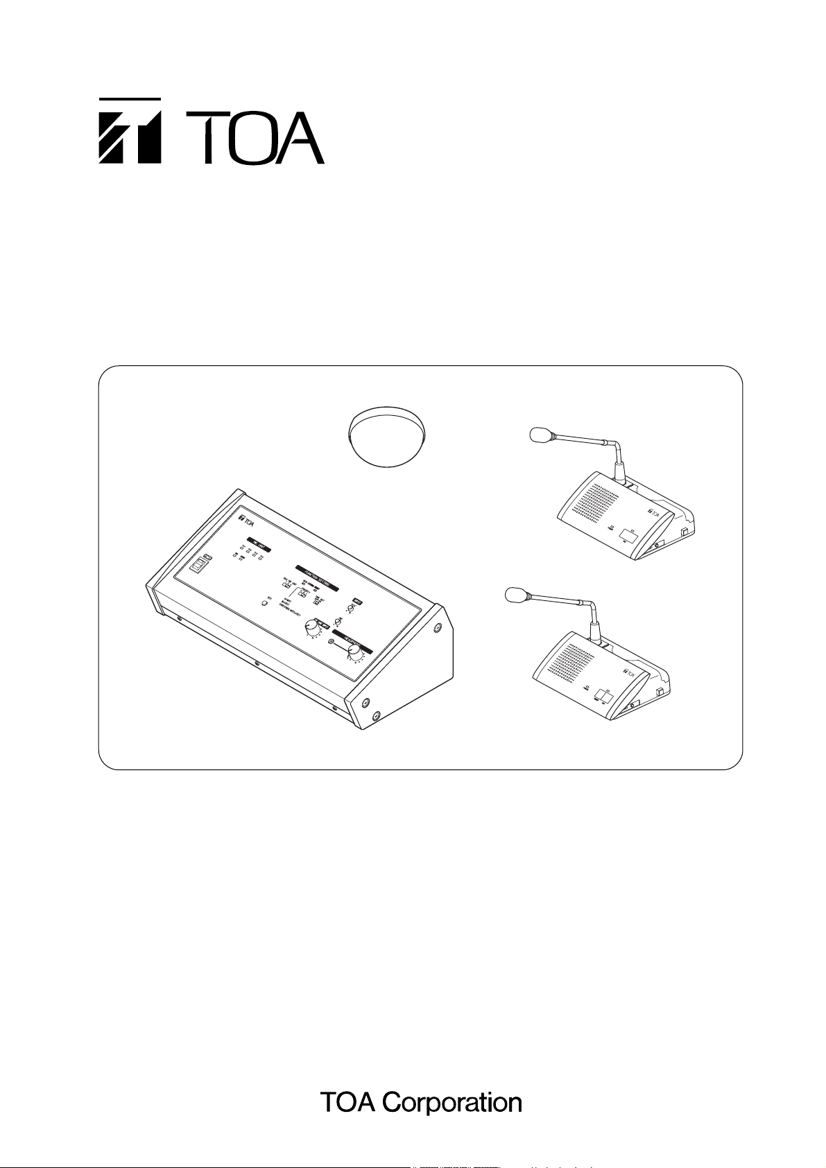
OPERATING INSTRUCTIONS
INFRARED CONFERENCE SYSTEM
TS-800 series
DELEGATE
UNIT TS-80
2
CH
AI
RM
AN UNIT TS-80
1
CENTRAL UNIT TS-800
TS-800 TS-801/-903
TS-802/-903
TS-905/-907
Thank you for purchasing TOA's Infrared Conference System.
Please carefully follow the instructions in this manual to ensure long, trouble-free use of your equipment.
Page 2

2
TABLE OF CONTENTS
1. SAFETY PRECAUTIONS .............................................................................................. 4
2. GENERAL DESCRIPTION ............................................................................................ 7
3. FEATURES ........................................................................................................................ 7
4. SYSTEM EQUIPMENT CONFIGURATION ............................................................. 8
5. NOMENClATURE AND FUNCTIONS
5.1. Central Unit TS-800 ........................................................................................................ 9
5.2. Chairman Unit TS-801 .................................................................................................. 12
5.3. Delegate Unit TS-802 ................................................................................................... 15
6. OPERATION
6.1. Initiating Speech ............................................................................................................ 18
6.2. Initiating Priority Speech (TS-801 only) ......................................................................... 19
7. FUNCTION SETTINGS
7.1. Setting the Maximum Number of Simultaneous Speakers ............................................ 20
7.2. Speech Priority Settings
7.2.1. Mode A: first-in/first-out priority (factory-preset switch position) .......................... 20
7.2.2. Mode B: last-in/first-out priority ............................................................................ 20
7.2.3. Mode C: priority fixed for first-enabled unit, and last-in/first-out priority
for all subsequent units ....................................................................................... 21
7.3. Mic-Off Function ............................................................................................................ 21
8. SYSTEM CONNECTION EXAMPLES .................................................................... 22
9. INFRARED SERVICE AREAS
9.1. Infrared Transmitter/Receiver ........................................................................................ 23
9.2. Chairman Unit and Delegate Unit ................................................................................. 24
10. INSTALLATION AND CONNECTIONS
10.1. Notes on Installation of the Infrared Transmitter/Receiver Unit .................................. 25
10.2. Infrared Transmitter/Receiver Unit Arrangement Examples ....................................... 26
10.3. Wiring between the Infrared Transmitter/Receiver Unit and the Central Unit
10.3.1. Notes on wiring ............................................................................................... 27
10.3.2. Distributor use ................................................................................................. 27
10.3.3. Wiring examples .............................................................................................. 27
10.4. Mounting the Infrared Transmitter/Receiver Unit
10.4.1. Ceiling mounting ............................................................................................. 29
10.4.2. Mounting on a microphone stand .................................................................... 30
10.5. Connections between the Infrared Transmitter/Receiver Unit and the Central Unit
10.5.1. Connecting ...................................................................................................... 31
10.5.2. Coaxial cable processing ................................................................................ 32
10.6. Using Wired Microphones and Sound Source Equipment
10.6.1. Wired microphone use .................................................................................... 37
10.6.2. Sound source equipment use ......................................................................... 37
10.7. Recording the Conference Contents ........................................................................... 38
Page 3

3
11. CHAIRMAN AND DELEGATE UNIT INSTALLATION AND SETTINGS ...... 39
12. CHAIRMAN AND DELEGATE UNIT POWER SUPPLY
12.1. BP-900 Lithium-Ion Battery
12.1.1. Inserting the lithium-ion battery ....................................................................... 40
12.1.2. Recharging ...................................................................................................... 41
12.2. AD-0910 AC Adapter .................................................................................................. 42
13. CENTRAL UNIT RACK MOUNTING ....................................................................... 43
14. INSTALLATION STATUS CONFIRMATION .......................................................... 44
15. APPENDIX
15.1. Confirming the Wiring Design
15.1.1. Values necessary for calculating the loss ....................................................... 45
15.1.2. Values necessary for calculating the voltage drop .......................................... 45
15.2. Computational Equation
15.2.1.
Finding the wiring loss
..................................................................................... 46
15.2.2. Finding the wiring voltage drop ....................................................................... 46
15.3. Design Examples
15.3.1. Example 1: When installing 4 TS-905 Infrared Transmitter/Receiver units
using 4 coaxial cables reaching from the Central unit: ................ 47
15.3.2. Example 2: When installing 4 TS-905 Infrared Transmitter/Receiver units
using 1 coaxial cable reaching from the Central unit
(one 4-branch distributor connected): .......................................... 48
15.3.3. Example 3: When installing each 4 TS-905 Infrared Transmitter/Receiver
units using 4 coaxial cables reaching from the Central unit
(four 4-branch distributors connected): ........................................ 50
15.3.4. Example 4: When installing 16 TS-905 Infrared Transmitter/Receiver Units
using 1 coaxial cable reaching from the Central unit
(five 4-branch distributors connected): ........................................ 51
16. IF A FAILURE IS DETECTED
16.1. Chairman Unit TS-801 and Delegate Unit TS-802 ...................................................... 53
16.2. Central Unit TS-800 .................................................................................................... 54
16.3. Battery Charger BC-900 .............................................................................................. 54
17. SPECIFICATIONS
17.1. Central Unit TS-800 ................................................................................................... 55
17.2. Chairman Unit TS-801, Delegate Unit TS-802 ............................................................ 56
17.3. Microphone TS-903, TS-904 ...................................................................................... 56
17.4. Infrared Transmitter/Receiver TS-905, TS-907 .......................................................... 57
17.5. Lithium-Ion Battery BP-900 ........................................................................................ 57
17.6. Battery Charger BC-900 ............................................................................................. 58
17.7. AC Adapter AD-900 ................................................................................................... 58
17.8. Distributor YW-1022 (2-branch distributor), YW-1024 (4-branch distributor) .............. 59
17.9. Rack Mounting Bracket MB-TS900 ............................................................................ 59
Page 4

4
When Installing the Unit
• Do not expose the unit to rain or an environment where it may be splashed by water or other liquids, as
doing so may result in fire or electric shock.
Applicable
to Central unit, Chairman unit, Delegate unit, Battery charger, and AC adapter
1. SAFETY PRECAUTIONS
• Before installation or use, be sure to carefully read all the instructions in this section for correct and safe
operation.
• Be sure to follow all the precautionary instructions in this section, which contain important warnings and/or
cautions regarding safety.
• After reading, keep this manual handy for future reference.
Safety Symbol and Message Conventions
Safety symbols and messages described below are used in this manual to prevent bodily injury and property
damage which could result from mishandling. Before operating your product, read this manual first and
understand the safety symbols and messages so you are thoroughly aware of the potential safety hazards.
Indicates a potentially hazardous situation which, if mishandled, could
result in death or serious personal injury.
WARNING
Indicates an imminently hazardous situation, which, if not avoided,
will result in death or serious injury.
DANGER
• Should the following irregularity be found during use, immediately switch off the power, take the batteries out
of the unit, and keep them away from fire. Failure to do so may cause a fire or explosion.
· If you find battery leakage, discoloration, deformation or damage.
· If you detect smoke or a strange smell coming out from the batteries.
• Do not deform, modify, nor solder the batteries. Dosing so may damage the battery's safety or protector
mechanism, causing the batteries to fire, leak, or explode.
• Never short the positive and negative terminals with a wire or other metallic objects. Also, avoid carrying or
keeping the batteries with metallic objects such as necklaces or hair pins. Doing so may cause the batteries
to fire, explode, leak, or heat.
• Never heat the batteries nor throw them into a fire. Doing so may damage the battery's gas relief valve or
safety mechanism, causing the batteries to fire or explode.
• Do not dip the batteries into water nor wet the battery terminals. This may corrode the batteries, possibly
causing them to fire, explode, leak, or heat.
• Note correct polarity (positive and negative orientation) when inserting the batteries into a battery charger.
Doing otherwise may cause them to fire, explode, leak, or heat.
• Do not use, keep, nor leave the batteries near fire or in locations where the temperature rises above 60°C
such as in a sun-heated car. Dosing so may damage the battery's safety or protector mechanism, causing
the batteries to fire, explode, leak, or heat.
• Be sure to use the BC-900 charger when recharging the batteries. Using other battery charger may cause
them to fire, explode, leak, or heat.
• Use the batteries only with the equipment specified. Failure to do so may cause the batteries to fire, explode,
leak, or heat.
• Do not drop the batteries nor give them a shock. Doing so may damage the battery's safety or protector
mechanism, causing the batteries to fire, explode, leak, or heat.
• There is a fear of loosing one's eyesight if a battery leakage gets in one's eyes. Wash it away with clean
water and consult a doctor immediately. If a battery leakage stains one's skin or clothes, wash it away with
clean water as there is a fear of impairing the skin.
Applicable to Lithium-ion battery
Page 5
5
• Use the unit only with the voltage specified on the unit. Using a voltage higher than that which is specified
may result in fire or electric shock.
• Do not cut, kink, otherwise damage nor modify the power supply cord. In addition, avoid using the power
cord in close proximity to heaters, and never place heavy objects -- including the unit itself -- on the power
cord, as doing so may result in fire or electric shock.
• Avoid installing or mounting the unit in unstable locations, such as on a rickety table or a slanted surface.
Doing so may result in the unit falling down and causing personal injury and/or property damage.
When the Unit is in Use
• Should the following irregularity be found during use, immediately switch off the power, disconnect the
power supply plug from the AC outlet and contact your nearest TOA dealer. Make no further attempt to
operate the unit in this condition as this may cause fire or electric shock.
· If you detect smoke or a strange smell coming from the unit.
· If water or any metallic object gets into the unit
· If the unit falls, or the unit case breaks
· If the power supply cord is damaged (exposure of the core, disconnection, etc.)
· If it is malfunctioning (no tone sounds.)
• To prevent a fire or electric shock, never open nor remove the unit case as there are high voltage
components inside the unit. Refer all servicing to your nearest TOA dealer.
• Do not place cups, bowls, or other containers of liquid or metallic objects on top of the unit. If they
accidentally spill into the unit, this may cause a fire or electric shock.
• Do not insert nor drop metallic objects or flammable materials inside the unit, as this may result in fire or
electric shock.
• Do not touch a plug during thunder and lightning, as this may result in electric shock.
• Stop charging if the batteries are not fully charged within 5 hours.
Continuously charging over 5 hours may cause the batteries to fire, explode, leak, or heat.
Applicable
to Battery charger and Lithium-ion battery
Applicable
to Central unit, Chairman unit, Delegate unit, Battery charger, and AC adapter
Indicates a potentially hazardous situation which, if mishandled, could
result in moderate or minor personal injury, and/or property damage.
CAUTION
When Installing the Unit
• These servicing instructions are for use by qualified personnel only.
To reduce the risk of electric shock, do not perform any servicing other than that contained in the operating
instructions unless you are qualified to do so. Refer all servicing to qualified service personnel.
• Be sure to follow the instructions below when rack-mounting the unit. Failure to do so may cause a fire or
personal injury.
· Install the equipment rack on a stable, hard floor. Fix it with anchor bolts or take other arrangements to
prevent it from falling down.
· To rack-mount the unit, use the supplied rack mounting hardware.
· When connecting the unit's power cord to an AC outlet, use the AC outlet with current capacity allowable to
the unit.
Applicable to Central unit
Page 6

6
• Never plug in nor remove the power supply plug with wet hands, as doing so may cause electric shock.
• When unplugging the power supply cord, be sure to grasp the power supply plug; never pull on the cord
itself. Operating the unit with a damaged power supply cord may cause a fire or electric shock.
• When moving the unit, be sure to remove its power supply cord from the wall outlet. Moving the unit with the
power cord connected to the outlet may cause damage to the power cord, resulting in fire or electric shock.
When removing the power cord, be sure to hold its plug to pull.
• Do not block the ventilation slots on the unit. Doing so may cause heat to build up inside the unit and result
in fire.
• Avoid installing the unit in humid or dusty locations, in locations exposed to the direct sunlight, near the heaters,
or in locations generating sooty smoke or steam as doing otherwise may result in fire or electric shock.
When the Unit is in Use
• Do not place heavy objects on the unit as this may cause it to fall or break which may result in personal
injury and/or property damage. In addition, the object itself may fall off and cause injury and/or damage.
• If dust accumulates on the power supply plug or in the wall AC outlet, a fire may result. Clean it periodically.
In addition, insert the plug in the wall outlet securely.
• Switch off the power, and unplug the power supply plug from the AC outlet for safety purposes when
cleaning or leaving the unit unused for 10 days or more. Doing otherwise may cause a fire or electric shock.
• Use the dedicated AC adapter for the unit. Note that the use of other adapter may cause a fire.
• Make sure that the volume control is set to minimum position before power is switched on. Loud noise
produced at high volume when power is switched on can impair hearing.
• Make sure that the volume control is set to minimum position before power is switched on. Loud noise
produced at high volume when power is switched on can impair hearing.
• When the unit is not in use for 10 days or more, be sure to take the battery out of the unit because battery
leakage may cause a fire, personal injury, or contamination of environment.
• Replace the battery only with the TOA BP-900. Using a battery other than designated may cause it to
explode. When you discard batteries, please contact the local dealer from whom you bought.
• Remove the power supply plug of charger from the AC outlet after charging completion, as doing otherwise
may cause a fire.
• When you discard batteries, please contact the local dealer from whom you bought.
Applicable to Lithium-ion battery
Applicable to Battery charger
Applicable to Chairman unit and Delegate unit
Applicable to Central unit
Applicable to Central unit, Chairman unit, Delegate unit, and Battery charger
Applicable to Central unit, Chairman unit, Delegate unit, Battery charger, and AC adapter
Applicable to Central unit, Chairman unit, Delegate unit, Battery charger, and AC adapter
This is a class A product.
In a domestic environment this product may cause radio interference in which case the user may be
required to take adequate measures.
Applicable to Central unit, Chairman unit, Delegate unit, and Battery charger
Page 7

7
2. GENERAL DESCRIPTION
The TOA TS-800 Series is a cordless infrared conference system that can be installed and removed quickly
and easily. Since the TS-801 Chairman unit and the TS-802 Delegate unit require no wiring, they permit easy
installation based on a free layout. The Infrared Transmitter/Receiver unit and recording equipment are
connected to the TS-800 Central unit, and the system function settings and status indications are performed at
the Central unit.
3. FEATURES
• Since the system is cordless, it can be easily installed and removed, permitting flexible relocation and
changes in system layout.
• The system's infrared communication method is not only resistant to radio interference and eavesdropping,
but it also permits simultaneous use of systems in adjacent conference rooms with no crosstalk.
• The number of Chairman and Delegate units can be varied as required depending on the number of
participants. Up to 64 Chairman and Delegate units can be used per system.
• The maximum number of Infrared Transmitter/Receiver units to be installed in a system is 16 when they are
all TS-905 units and 12 when they are all TS-907 units. (Also 12 when both models are mixed.)
• A function to restrict the number of speakers minimizes disorder that could result from simultaneous
communications by meeting participants.
• The speech system selection function permits operation when the unit's Talk key is pressed to be set to firstin-first-out, last-in-first-out, or other priority.
• The Mic-Off function automatically turns off the unit's microphone after 30 seconds, even if a user forgets to
turn off the microphone after speech completion.
• While the Chairman or Delegate unit is in use, its built-in monitor speaker is turned off, preventing acoustic
feedback*.
• The Central unit can be used in conjunction with wired microphones and output source equipment,
depending on application.
• Since the Central unit can be connected to recording equipment, it is ideal for use in preparing conference
minutes.
• The Chairman unit features a priority speech key which allows it to take precedence over Delegate units
when speaking.
• The dedicated microphone used by Chairman and Delegate units employs an XLR connector that not only
permits easy attachment and detachment of the microphone, but also saves space when stored.
• Both Chairman and Delegate units can be operated on both their built-in rechargeable lithium-ion batteries
or AC power supply.
• Two types of dedicated microphones are made available for the Chairman and Delegate units: "standard"
and "long."
* Acoustic feedback: A squeal or howl from the speaker caused by an audio loop condition in which part of the
speaker output is picked up by the same microphone, and subsequently amplified and
output from the speaker again, quickly building in intensity.
Page 8
8
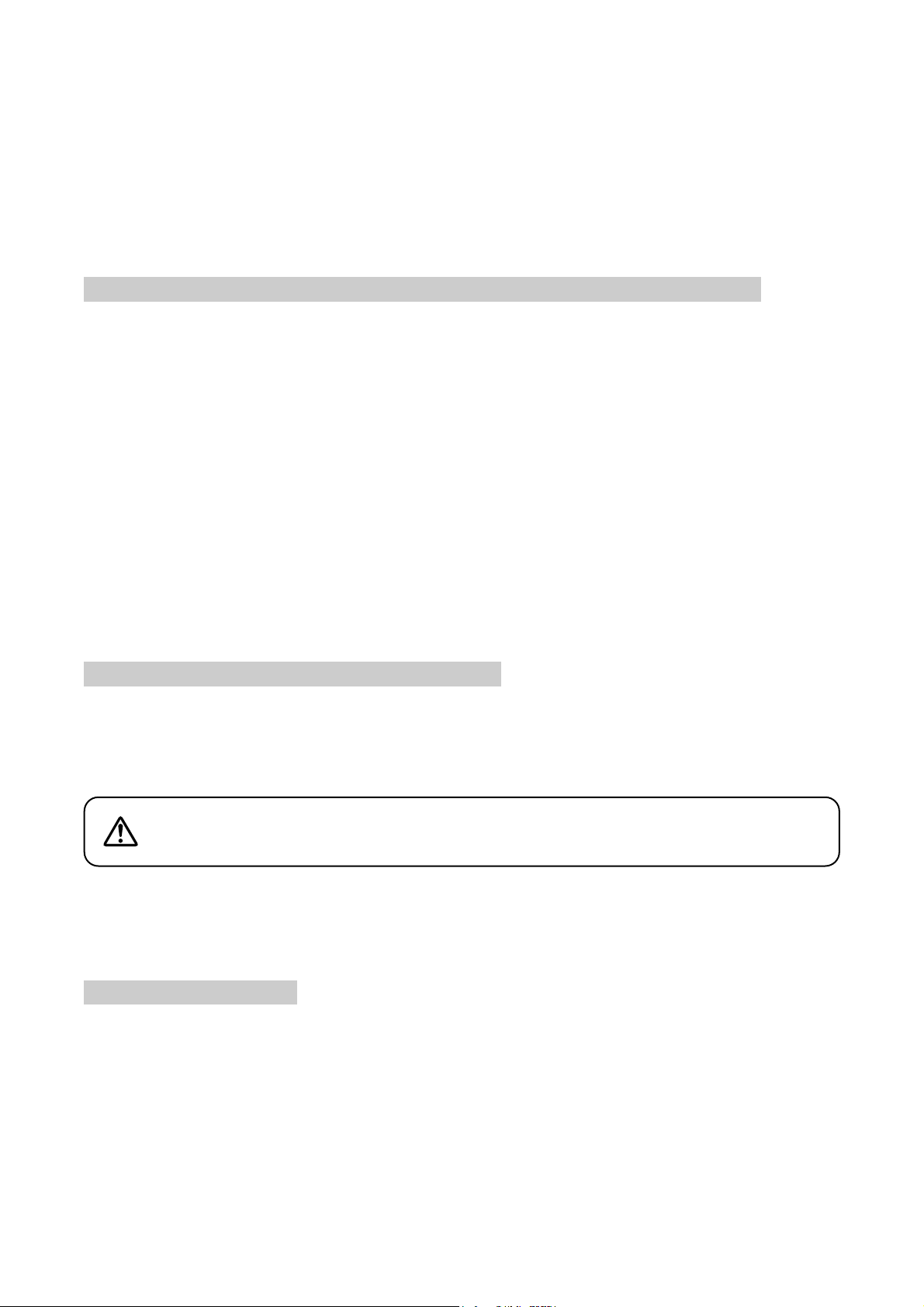
4. SYSTEM EQUIPMENT CONFIGURATION
Distributor
YW-1024 (4-branch distributor)
or
YW-1022 (2-branch distributor)
Note
The maximum number of Infrared Transmitter/Receiver units to be installed
TS-905 only: 16
TS-907 only: 12
(Also 12 when both models are mixed.)
Infrared transmitter/receiver
TS-905 or TS-907
C
EN
T
R
AL
Central unit
TS-800
CHAI
RMA
N
UN
I
T TS-80
1
Chairman unit
TS-801
UNI
T TS-800
TS-905 or TS-907
AC adapter
(supplied with the TS-800)
Power cord
(supplied with the TS-800)
Microphone (standard) TS-903
or
Microphone (long) TS-904
Infrared transmitter/receiver
D
E
L
E
G
A
T
E
UNI
T TS-80
2
D
E
LE
GA
T
E
UN
IT TS-80
2
AC adapter AD-0910
(for TS-801/802)
Delegate unit
TS-802
Lithium-ion battery BP-900
(for TS-801/802)
Battery charger BC-900
(for BP-900)
Rack mounting bracket MB-TS900
(for TS-800)
Page 9
9
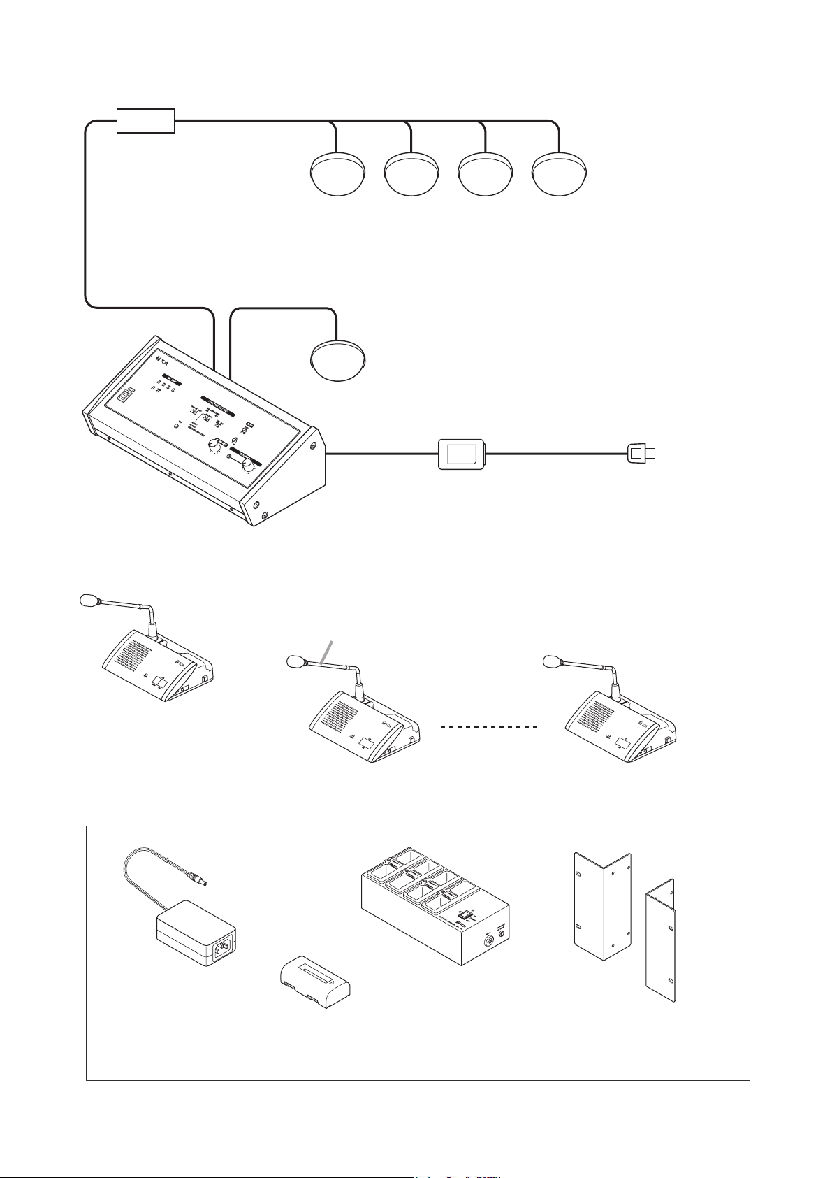
5. NOMENCLATURE AND FUNCTIONS
5.1. Central Unit TS-800
[Top]
1. Power switch
Setting this switch to the ON position causes the
Power indicator to light.
2. Audio signal receiving indicators
[Ch1/Ch2/Ch3/Ch4]
Light up when audio signals are received from
either Chairman or Delegate units. Audio signals
are transmitted or received through 4 channels.
The number of channels to be used can be set
with the Simultaneous Speaker No. Setting switch
(10). These indicators light in the same number as
that of the Chairman or Delegate units currently
being used for speech. (Which indicator will light is
not specified.)
3. Data signal receiving indicator
Lights when control data is received from the
Chairman or Delegate unit.
4. Battery indicator
Flashes when the lithium-ion battery of the
Chairman or Delegate unit nears complete
discharge. (In this event, the Microphone In-Use
indicator and the Speech indicator on the
corresponding unit also flash.)
Note
Be sure to replace the lithium-ion battery of the
corresponding unit immediately if this indicator
begins to flash.
5. External control communication indicator
Remains lit during communications with a
computer (PC) or operation panel connected to
the RS-232C terminal.
6. External control priority indicator
Either lights or flashes when a PC or operation
panel connected to the RS-232C terminal
performs priority operation. In this event, three
function setting switches (10), (11), and (12)
cannot be used.
7. AUX input volume control
Adjusts the input signal level of the AUX Input
Terminal (17) located on the rear panel.
8. MIC input volume control
Adjusts the input level of the MIC Input Terminal
(18) on the rear panel.
9. Installation check button
Installation status for the Infrared Transmitter/Receiver,
Chairman unit, and Delegate unit can be checked.
(Refer to p. 44.)
5 6 7 8
CENTRAL UNIT TS-800
2
Ch4Ch3Ch2Ch1
BATTERYDATA
3
4
POWER
1
TEST
FUNCTION SETTINGMIC UNIT
DATA–EXT–PRIORITY
PRIORITY
MIC
UNITMAX
124
ABC
A: FIRST
B: LATEST
C: FIRST: FIXED, NEXT: LATEST
TIME OUT
ON
OFF
INPUT
AUX
100
MIC
MIC UNIT INPUT
100
100100
HEADPHONES
9 10 11 12 13 14 15
Page 10

10
10. Simultaneous speaker No. setting switch
Used to set the number of Chairman and
Delegate units that can be simultaneously
operated. The indications [1], [2], and [4]
represent the number of simultaneously operable
units. (Refer to p. 20.)
Note
This switch is factory-preset to the [1] position.
11. Speech priority selector switch
Determines the priority mode when the Talk key
of the Chairman or Delegate unit is pressed.
(Refer to p. 20.)
A: First-in-first-out priority
B: Last-in-first-out priority
C: Priority fixed for the first unit, and last-in-first-
out priority for all other subsequent units.
Note
This switch is factory-preset to the [A] position.
12. Mic-off setting switch
Automatically turns off Chairman or Delegate unit
microphones 30 seconds after speech is
completed if the user should neglect to turn off
the microphone. (Refer to p. 21.)
Note
This switch is factory-preset to the OFF position.
13. Speech volume control
Adjusts the microphone volume of the Chairman
unit and Delegate unit.
14. Headphone jack (Mini-jack)
Connects to a headphone.
15. Headphone volume control
Adjusts the sound volume of the headphone.
Page 11
11
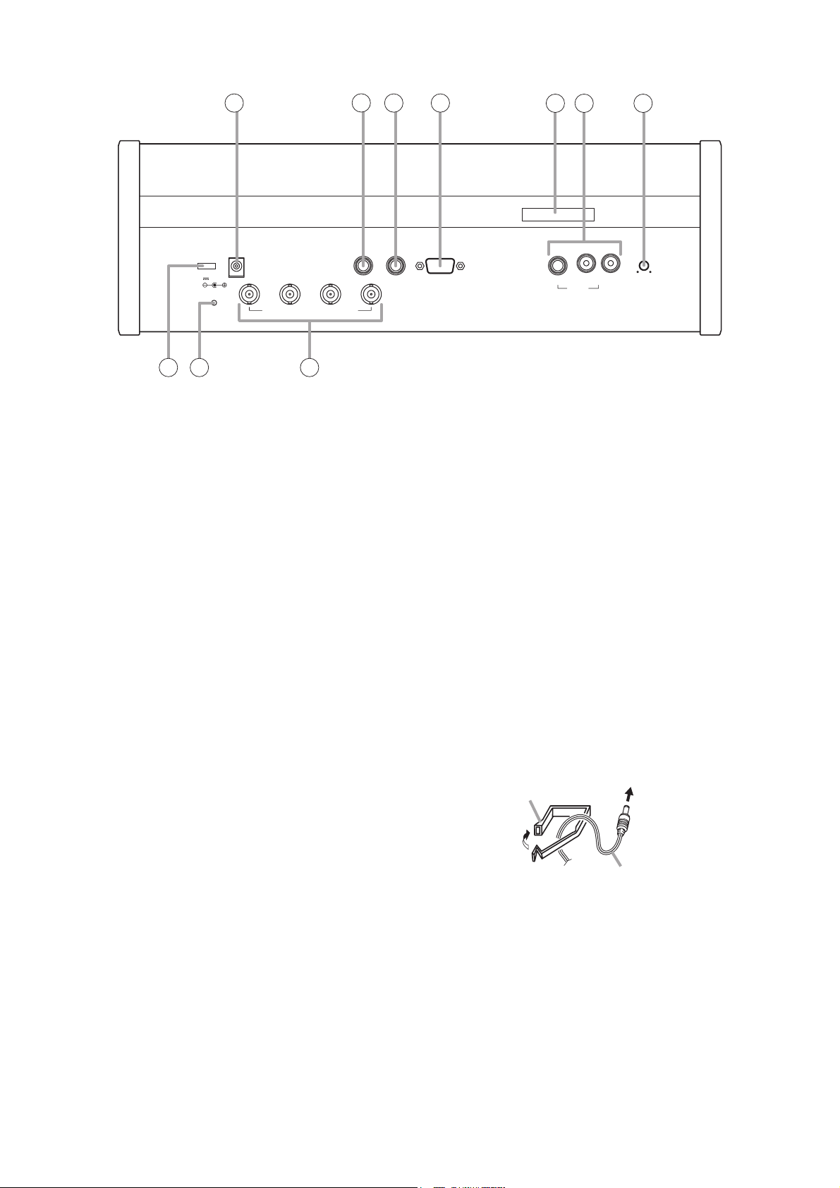
[Bottom]
16. DC input
Connect the supplied AC adapter to this terminal.
17. AUX input terminal
Connect a CD player, tape recorder, or other
similar equipment to this terminal.
18. MIC input terminal
Connect a wired microphone to this terminal.
19. External control terminal
Connect this terminal to the serial port of a PC,
operation panel, or other external control
equipment.
20. Marking plate
Shows the Manufacturer's Name, Model Name,
and Electrical Rating.
21. Recording output terminal
Connect an Alternate Recording Deck or MD
recorder. An amplifier can also be connected for
public address applications.
22. Priority chime volume control
Adjusts the output volume of the chime tone that
sounds when the Priority Speech key on the
Chairman unit is pressed.
23. Infrared transmitter/receiver unit I/O terminals
Connect the Infrared Transmitter/Receiver unit or
distributor to this terminal. By using the YW-1022
(2-branch distributor) and/or YW-1024 (4-branch
distributor), the following maximum number of
Infrared Transmitter/Receiver units can be
connected: 16 units when they are all TS-905
units, 12 units when they are all TS-907 units.
(Also 12 units when both models are mixed.)
24. Short circuit indicator
Lights when the Infrared Transmitter/Receiver
unit or its connected cable is shorted.
25. Cable clip
Run the AC adapter cable through this clip to
prevent its plug from being removed from the DC
input.
16 18 1917
DC24V 3A(MAX)
SHORT
INFRARED TRANSMITTER/RECEIVER
2425
23
MIC EXT CONTROL CHIME
AUX
REC OUT
2120
22
To the DC input
Cable clip
AC adapter cable
Page 12
12
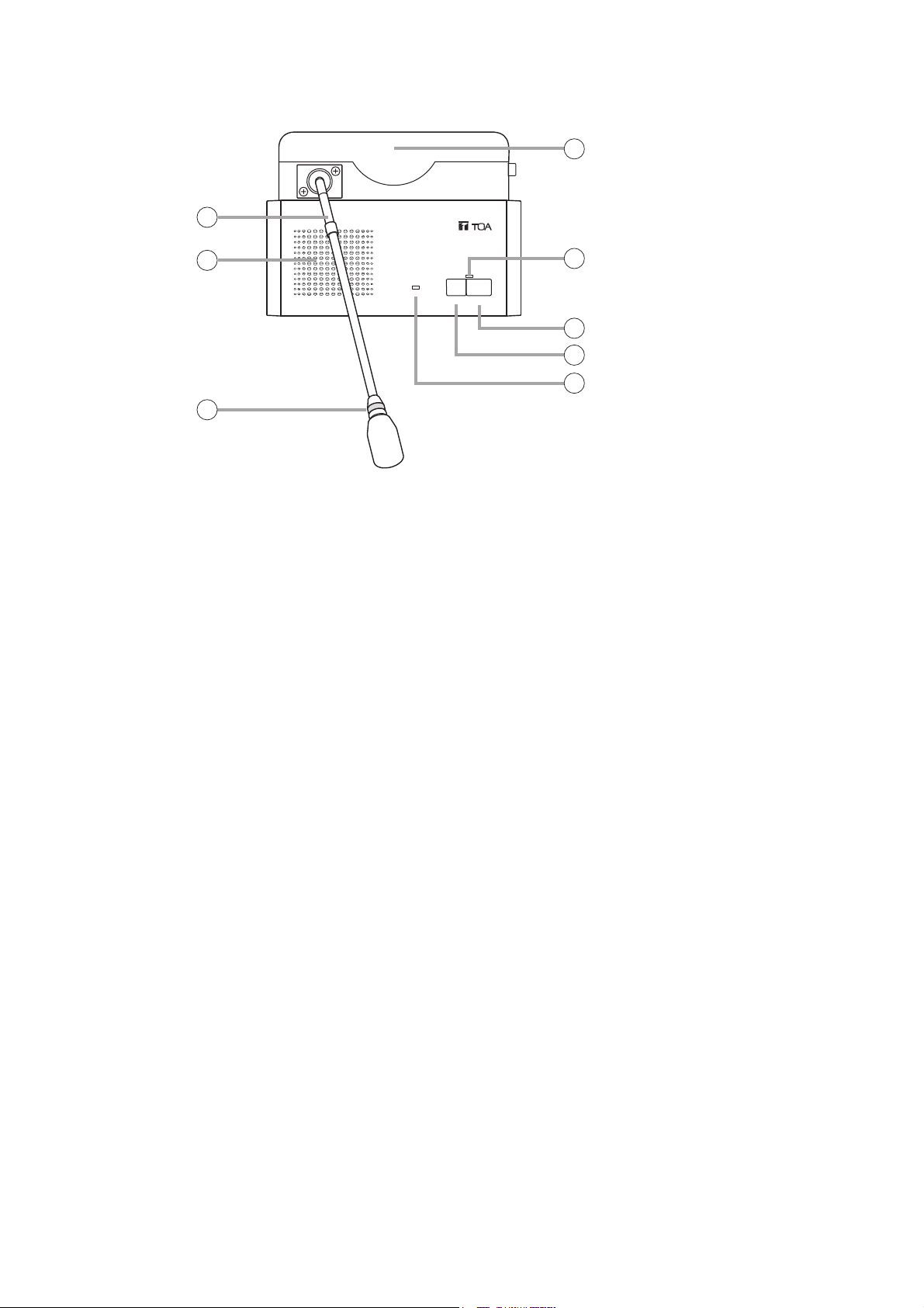
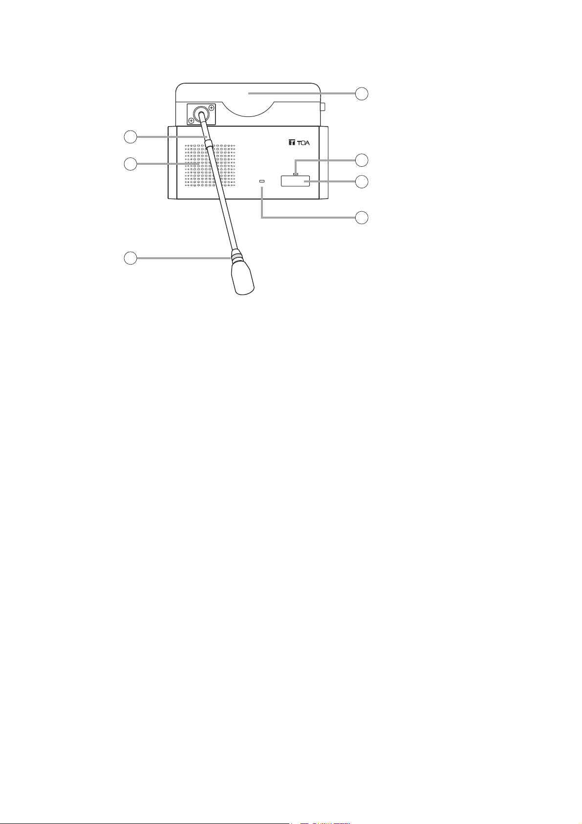
5.2. Chairman Unit TS-801
[Top]
1. Monitor speaker
Speech input from other Chairman or Delegate
units and the Central unit is output from this
speaker.
Use the right-side Monitor Volume Control (13) to
adjust the volume. No sound is output from the
speaker of the unit in use while speaking.
2. Microphone
Use either the TS-903 (Standard) or TS-904
(Long) dedicated microphone.
3. Microphone in-use indicator
Lights when the microphone is turned on (for
speech) and flashes when the battery level is low.
4. Infrared emitter/detector
The device used to transmit and receive infrared
communication signals is built inside this panel.
Note
Never place any object that could block infrared
signal access to this part of the unit, as this would
prevent the unit from transmitting or receiving its
required infrared signal.
5. Speech indicator
Remains lit while the microphone is in use (during
speech). The indicator flashes when the unit is out
of the communications service area.
6. Talk key
When this key is pressed, both the Microphone InUse indicator (3) and the Speech indicator (5)
light, and the microphone turns on. Pressing this
key again extinguishes both indicators and turns
off the microphone.
7. Priority speech key
Press this key continuously while speaking.
A chime tone sounds when the key is pressed.
(The chime can be disabled using the Priority
Chime Disable switch (11).)
The microphone turns on and both the
Microphone In-Use indicator (3) and the Speech
indicator (5) remain lit as long as the key is held
down, allowing the voice input from the unit to
take precedence over other units. During this
interval, other Delegate units cannot be used.
While this key is held down, only the priority
speech input is relayed to the Central unit's
recording output.
8. Power indicator
Lights when the power is switched ON.
This indicator also flashes when the battery level
is low or the unit is outside the communications
service area.
Note
No microphone is supplied with the TS-801 Chairman unit.
4
2
1
3
POWER
CHAIRMAN UNIT TS-801
5
TALK
PRIORITY
6
7
8
Page 13
13
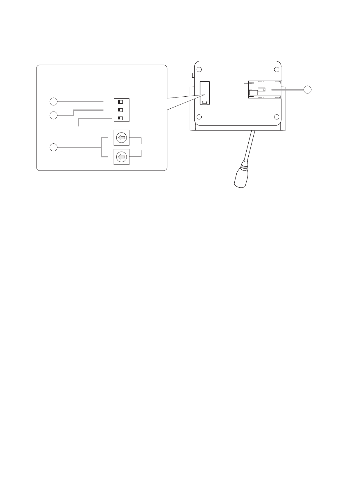
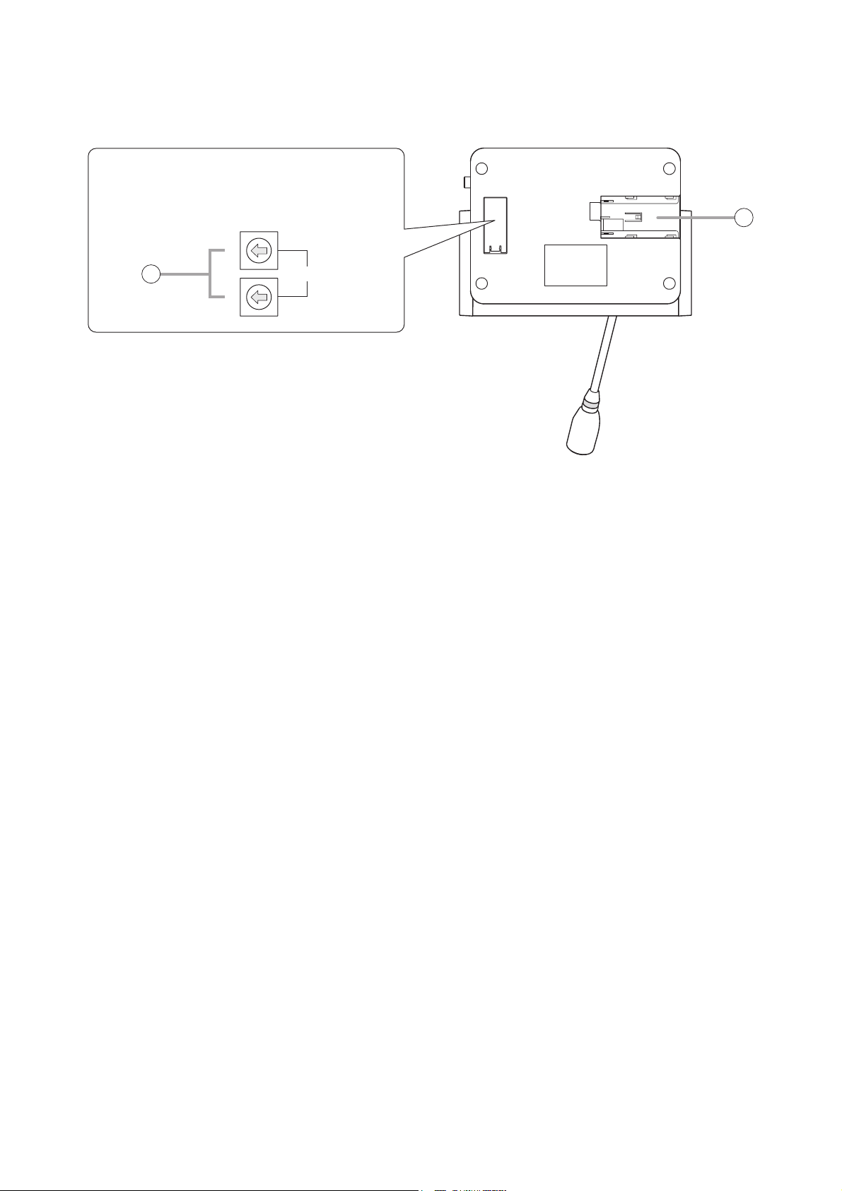
[Bottom]
9. Lithium-ion battery compartment
Install only a dedicated BP-900 Lithium-Ion
Battery in this compartment.
10. Interrupted operation reset switch [5]
Following completion of a priority speech, this
switch is used to reset the operating status of
Chairman and Delegate units whose operations
were interrupted by the depression of a Priority
Speech key (7).
Set the switch to RESTORE in order to resume
the mode in operation prior to initiation of the
priority speech, and to RESET when resumption
is not desired.
Note
This switch is factory-preset to the RESET
position.
11. Priority chime disable switch [6]
Disables the chime that sounds when the Priority
Speech key is pressed.
Set this switch to OFF when sound output is
desired, and to ON when no sound is desired.
Note
This switch is factory-preset to the OFF position.
12. Unit address number setting switch
Set the unit address number ([01] – [64]), taking
care to ensure that the same number is not
duplicated in the system.
If the number [00] is assigned to a unit, the user
of that unit cannot speak. However, the unit can
be used for monitoring.
Note
This number is factory-preset to [00].
Remove the cover on the bottom side of the unit to expose its setting switches.
Note
The label describing the setting switches is shown
in the following figure.
PRIORITY
ON
1 2 3
10
11
RESET
OFF
Not used.
10
RESTORE
CHIME MUTE
ON
NOT USE
9
12
1
UNIT ID
Page 14
14
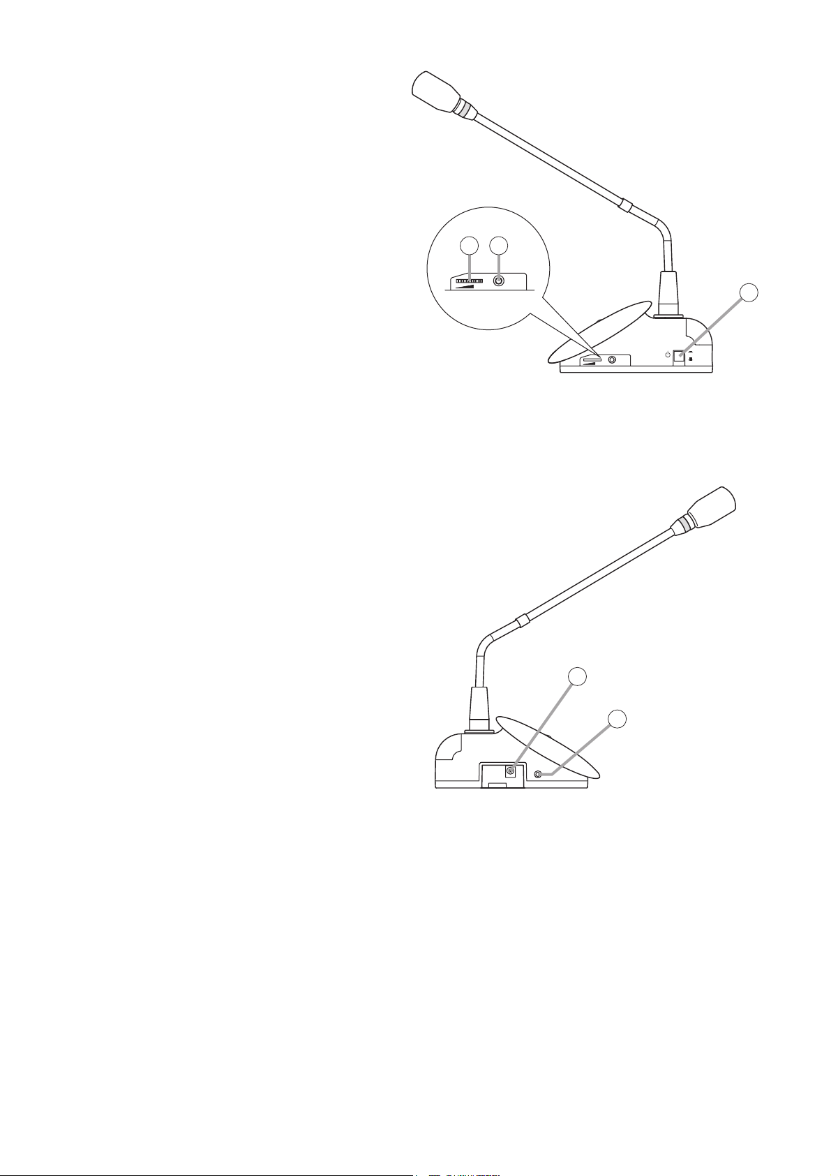
[Right side]
13. Monitor volume control
Adjusts the output volume of the monitor
speaker and headphone.
14. Headphone jack
Connect a headphone to this jack (mini-jack).
Connecting the headphone cuts off the
output from the monitor speaker.
Note
A headphone jack is located on both the left
and right side panels.
15. Power switch
Press this switch to switch on the power.
To switch off the power, press this switch
again.
[Left side]
16. DC inlet
Connect the dedicated AD-0910 AC Adapter
to this terminal.
Note: No microphone is supplied with the TS-801 Chairman unit.
13 14
HEADPHONES
HEADPHONES
POWER
15
ON
OFF
16
14
HEADPHONES
Page 15
15
5.3. Delegate Unit TS-802
[Top]
1. Monitor speaker
Speech input from other Chairman or Delegate
units and the Central unit is output from this
speaker.
Use the right-side Monitor Volume Control (10) to
adjust the volume. No sound is output from the
speaker of the unit in use while speaking.
2. Microphone
Use either the TS-903 (Standard) or TS-904
(Long) dedicated microphone.
3. Microphone in-use indicator
Lights when the microphone is turned on (for
speech) and flashes when the battery level is low.
4. Infrared emitter/detector
The device used to transmit and receive infrared
communication signals is built inside this panel.
Note
Never place any object that could block infrared
signal access to this part of the unit, as this would
prevent the unit from transmitting or receiving its
required infrared signal.
5. Speech indicator
Remains lit while the microphone is in use (during
speech). The indicator flashes when the unit is out
of the communications service area.
6. Talk key
When this key is pressed, both the Microphone InUse indicator (3) and the Speech indicator (5)
light, and the microphone turns on. Pressing this
key again extinguishes both indicators and turns
off the microphone.
7. Power indicator
Lights when the power is switched ON.
This indicator also flashes when the battery level
is low or the unit is outside the communications
service area.
Note
No microphone is supplied with the TS-802 Delegate unit.
4
2
1
3
POWER
DELEGATE UNIT TS-802
5
TALK
6
7
Page 16
16
[Bottom]
8. Lithium-ion battery compartment
Install only a dedicated BP-900 Lithium-Ion
Battery in this compartment.
9. Unit address number setting switch
Set the unit address number ([01] – [64]), taking
care to ensure that the same number is not
duplicated in the system.
If the number [00] is assigned to a unit, the user of
that unit cannot speak. However, the unit can be
used for monitoring.
Note
This number is factory-preset to [00].
Remove the cover on the bottom side of the unit to expose its setting switches.
Note
The label describing the setting switches is shown
in the following figure.
10
8
9
1
UNIT ID
Page 17

17
[Right side]
10. Monitor volume control
Adjusts the output volume of the monitor
speaker and headphone.
11. Headphone jack
Connect a headphone to this jack (mini-jack).
Connecting the headphone cuts off the
output from the monitor speaker.
Note
A headphone jack is located on both the left
and right side panels.
12. Power switch
Press this switch to switch on the power.
To switch off the power, press this switch
again.
[Left side]
13. DC inlet
Connect the dedicated AD-0910 AC
Adapter to this terminal.
Note: No microphone is supplied with the TS-802 Delegate unit.
10
11
HEADPHONES
HEADPHONES
POWER
12
ON
OFF
13
11
HEADPHONES
Page 18

18
6. OPERATION
6.1. Initiating Speech
Step 1. Press the Talk key on the Chairman or
Delegate unit.
The Speech indicator and Microphone
In-Use indicator light, placing the unit in
speech mode.
No sound is output from the monitor
speaker while both indicators are
continuously lit.
Note
The unit cannot be used for speech if the
indicators do not light.
Step 2. Speak into the microphone.
Step 3. Press the Speech key again after
speech completion.
The indicators extinguish, and sound
can be output from the monitor speaker.
Note
When the user forgets to turn off the
microphone, the Mic-Off function
automatically turns off the microphone
approximately 30 seconds after speech
completion. (Refer to p. 21.)
Microphone
in-use indicator
CHAIRMAN UNIT TS-801
POWER
TALK
PRIORITY
The figure shows the TS-801.
Speech indicator
Page 19

19
6.2. Initiating Priority Speech (TS-801 only)
Step 1. Speak while holding down the Priority Speech
key.
Both the Speech indicator and the Microphone
In-Use indicator light, placing the unit in priority
speech mode. No sound is output from the
monitor speaker while both indicators are
continuously lit. A chime tone* sounds at other
units, preventing them from being used for
speaking.
* The chime tone can be enabled or disabled
using the Priority Chime Disable switch
located on the underside of the unit.
ON: No chime sounds.
OFF: Chime sounds. (Factory-preset
position)
Note
When two or more Chairman units are used in
a system, a priority speech currently in
progress from one unit can be interrupted by
pressing the Priority Speech key of another
Chairman unit, allowing the latter unit to go
through. (Last-in-first-out priority)
Step 2. Release the Priority Speech key after speech
completion.
Both indicators extinguish, and sound can be
output from the monitor speaker.
Note
After the priority speech is completed, the other
interrupted unit resumes operation as
predetermined by the setting of the Interrupted
Operation Reset switch located on the bottom
side of the unit.
RESTORE: Resumes the unit's mode prior to
being interrupted by the priority
speech.
RESET: Resets all units currently being
used for speech (Factory-preset
position). When an interrupted
party wishes to continue to
speak, the Speech key must
again be pressed.
Note
The Chairman unit that initiated the priority
speech automatically returns to its original
mode following priority speech completion,
regardless of its Operation Reset switch
setting.
The Chairman unit features the function that allows its speech to take precedence over that of the Delegate
unit. The Chairman unit's speech is prior to the AUX and MIC inputs.
Microphone
in-use indicator
POWER
CHAIRMAN UNIT TS-801
PRIORITY
Speech
TALK
indicator
Interrupted operation
reset switch
Priority chime disable switch
(Inside of the cover)
1 2 3
RESET
OFF
PRIORITY
ON
RESTORE
CHIME MUTE
ON
NOT USE
TS-801
bottom side
Page 20

20
7. FUNCTION SETTINGS
7.1. Setting the Maximum Number of Simultaneous Speakers
Using the Simultaneous Speaker No. Setting switch on the TS-800 Central
Unit, set the maximum total number of Chairman and Delegate units that
can simultaneously initiate speech.
Set the switch to [1], [2], or [4] depending on the type of the conference.
These numbers indicate the number of units that can simultaneously
initiate speech. (This switch is factory-preset to the [1] position.)
Note
When the Talk key is pressed at a unit exceeding the set maximum
number, the corresponding unit can only initiate speech as determined in
the speech priority settings referred to in the next section.
7.2. Speech Priority Settings
Operation following the depression of the Talk key on a Chairman or
Delegate unit, when the maximum number of speakers that can be
simultaneously initiated is reached, can be selected with the Speech
Priority Selector switch on the TS-800 Central unit.
7.2.1. Mode A: first-in/first-out priority (factory-preset switch position)
Speech is initiated on a first-come/first-served basis. When the maximum
number of speakers is reached, subsequent speech requests cannot be
accepted, even if the Talk key is pressed.
• Example showing the number of simultaneous speakers set to [2].
7.2.2. Mode B: last-in/first-out priority
When the maximum number of simultaneous speakers is reached, input from the most recent subsequent
Talk key-enabled Chairman or Delegate unit takes precedence, thus rendering earlier enabled units
inoperable.
• Example showing the number of simultaneous speakers set to [2].
FUNCTION SETTING
DATA–EXTERNAL–PRIORITY
MIC
UNITMAX
124
PRIORITY
ABC
A: FIRST
B: LATEST
C: FIRST: FIXED, NEXT: LATEST
TIME OUT
Simultaneous speaker No.
setting switch
FUNCTION SETTING
DATA–EXTERNAL–PRIORITY
MIC
UNITMAX
124
PRIORITY
ABC
A: FIRST
B: LATEST
C: FIRST: FIXED, NEXT: LATEST
TIME OUT
OFF
OFF
ON
ON
Chairman or Delegate unit
[First unit]
Press the talk key.
First unit: Speech possible.
[Second unit]
TALK TALKTALK
Press the talk key.
First unit: Speech possible.
Second unit: Speech possible.
[Third unit]
Press the talk key.
First unit: Speech possible.
Second unit: Speech possible.
Third unit: Speech not possible.
Speech priority selector switch
Chairman or Delegate unit
[First unit]
[Second unit]
[Third unit]
Press the talk key.
First unit: Speech possible.
TALK TALKTALK
Press the talk key.
First unit: Speech possible.
Second unit: Speech possible.
Press the talk key.
First unit: Speech cancelled.
Second unit: Speech possible.
Third unit: Speech possible.
Page 21

21
7.2.3. Mode C: priority fixed for first-enabled unit, and last-in/first-out priority for all subsequent units
The first-enabled Chairman or Delegate unit is given fixed speech priority until its Talk key is pressed again.
All subsequent Talk key-enabled units are given last-in/first-out priority, as in Mode B.
• Example showing the number of simultaneous speakers set to [2].
7.3. Mic-Off Function
This function automatically turns off the microphone if the user neglects to turn it off following speech
completion.
This function is enabled when the Mic-Off Setting switch on the
TS-800 Central Unit is set to the ON position.
The microphone automatically turns off if a duration of silence
lasts for about 30 seconds.
It is recommended that the Mic-Off switch be set to the OFF
position when not specifically using this function. (The Mic-Off
switch is factory-preset to the OFF position.)
Notes
• When the Mic-Off switch is set to the ON position, the
microphone automatically turns off if there is a silent interval of
about 30 seconds, even though a speech may be in progress.
In conferences, where long pauses during speeches can be
experienced, set the switch to the OFF position.
• The Mic-Off function may not be operated correctly in highnoise areas.
Chairman or Delegate unit
[First unit]
[Second unit]
TALK TALK TALKTALK
[Third unit]
[Fourth unit]
Press the talk key.
First unit: Speech possible.
Press the talk key.
First unit: Speech possible.
Second unit: Speech possible.
Press the talk key.
First unit: Speech possible.
Second unit: Speech cancelled.
Third unit: Speech possible.
Press the talk key.
First unit: Speech possible.
Second unit: Speech cancelled.
Third unit: Speech cancelled.
Fourth unit: Speech possible.
FUNCTION SETTING
DATA–EXTERNAL–PRIORITY
MIC
124
PRIORITY
UNITMAX
ABC
A: FIRST
B: LATEST
C: FIRST: FIXED, NEXT: LATEST
TIME OUT
ON
OFF
Mic-off setting switch
Page 22

22
8. SYSTEM CONNECTION EXAMPLES
PC
Central unit TS-800
AC adapter
(supplied with the TS-800)
Power cord
(supplied with the TS-800)
DC24V 3A(MAX)
SHORT
INFRARED TRANSMITTER/RECEIVER
MIC RS-232C CHIME
AUX
REC OUT
Speaker Amplifier
Distributor
YW-1024 (4-branch distributor)
or
YW-1022 (2-branch distributor)
Cassette player
Alternate recording deck
Infrared transmitter/receiver
TS-905 or TS-907
For details of the installation and connection of the Infrared Transmitter/Receiver unit,
please refer to p. 25 "10. INSTALLATION AND CONNECTIONS."
Chairman unit TS-801
or
Delegate unit TS-802
CHAIRMAN
UNIT TS
-801
Headphone
Distributor block diagram
[YW-1022] [YW-1024]
Loss of 4.5dB
Mixing
Distribution 1
Distribution 2
Distributor
Loss of 4.5dB
To avoid an increase in loss, do not perform connections
Note:
Impossible
Mixing
between distribution terminals.
Loss of 8.5dB
Distribution 1
Distribution 2
Distribution 3
Distributor
Distribution 4
Loss of 8.5dB
Impossible
Impossible
Impossible
Page 23

23
9. INFRARED SERVICE AREAS
9.1. Infrared Transmitter/Receiver
Notes
• Infrared signals cannot reach the Infrared Transmitter/Receiver unit if it is hidden behind the user or other
objects. Install multiple Transmitter/Receiver units in line-of-sight from all Chairman and Delegate units.
• Install the Infrared Transmitter/Receiver units in such a way that each Chairman and Delegate unit can
always communicate with two or more Transmitter/Receiver units. If installed in such a way that
communication is only established with one Transmitter/Receiver unit, the infrared signal may be blocked by
persons or other objects, possibly causing a momentary loss of signal reception.
Model Ceiling height Radius of communication area
2.5 m
Approx. 7.0 m
3.0 m
TS-905 3.5 m
Approx. 6.5 m
4.0 m
4.5 m
5.0 m
5.5 m
Approx. 6.0 m
TS-907 6.0 m
6.5 m
7.0 m
• TS-905
• TS-907
Ceiling height
2.5 – 4.5 m
Ceiling height
5 – 7 m
150°
Radius of communication area
90°
Radius of
communication area
Page 24

24
9.2. Chairman Unit and Delegate Unit
120°
120°
15°
90°
15°
CHAIRMAN UNIT TS-801
POWER
TALK
PRIORITY
Page 25

25
10. INSTALLATION AND CONNECTIONS
10.1. Notes on Installation of the Infrared Transmitter/Receiver Unit
Installing the Infrared Transmitter/Receiver unit in locations exposed to sunlight or in proximity to such infrared
sources as fluorescent lights could result in system failures or the introduction of noise into the system. Avoid
installing the Infrared Transmitter/Receiver unit in close proximity to infrared sources, as instructed below:
[Avoid direct sunlight]
• Cover windows with curtains or blinds to shield
the unit from direct exposure to sunlight.
• Install the unit at lease 2 – 3 meters away from
the nearest window.
[Keep away from fluorescent lights]
Position the unit at least 50 cm away from fluorescent lights.
[Keep away other infrared light sources]
• Lighting equipment
• LCD projectors, overhead projectors, incandescent lamps, etc.
• Mercury-arc lamps
• Plasma displays
• Remote controllers, infrared microphones, infrared equipment such as infrared LANs.
• Dimmers
2 – 3 m
Sunlight
Ceiling
Fluorescent lights
50 cm or more 50 cm or more
Page 26

26
10.2. Infrared Transmitter/Receiver Unit Arrangement Examples
The area range that an Infrared Transmitter/Receiver unit covers differs depending on the height from the
Chairman/Delegate units to the ceiling. (Refer to p. 23.)
Arrange the Infrared Transmitter/Receiver units so that all Chairman and Delegate units are included in the
service area.
Note
The maximum number of Infrared Transmitter/Receiver units to be installed is 16 when they are all TS-905
units and 12 when they are all TS-907 units. (Also 12 when both models are mixed.)
[Conference room measuring 30 x 30 meters]
Arranging the units at intervals as illustrated
permits the service area to cover every corner of
the room.
Note
Determine which to use TS-905 or TS-907
depending on the ceiling height.
[Conference room using round tables]
All Chairman and Delegate units are arranged
around the table, in which case only one
Infrared Transmitter/Receiver unit may suffice
for complete coverage of conference
communications.
However, it is highly recommended that two
or more Transmitter/Receiver units be
installed in order to avoid accidental
interruptions of communications.
Communication area
that each unit covers
Infrared transmitter/receiver
6 m6 m 9 m9 m
6 m
Infrared transmitter/receiver
10 – 15 m
6 m9 m 9 m
Communication area
that the unit covers
10 – 15 m
Page 27

27
10.3. Wiring between the Infrared Transmitter/Receiver Unit and the Central Unit
10.3.1. Notes on wiring
When two or more Infrared Transmitter/Receiver units receive infrared signals from the Chairman and
Delegate units, the signal reception level increases if input signals to each Transmitter/Receiver unit are in
phase. If not in phase, the signal reception level may decrease.
• To put signals in phase, ensure that the following cable length between two components are identical.
Length between each Infrared Transmitter/Receiver unit and the Central unit
: L + M0 + N0 = M1 + N0 = N1
Note: This distance must always be the same even if a distributor is included in the wiring.
Length between Infrared Transmitter/Receiver unit and distributor: L
Length between distributors (where two distributors are connected): M0
Length between distributor and Central unit: N0
(In the above figure, since there is only one N0 connection, the length need not be matched for the N0 line.)
• The maximum cable length between each Infrared Transmitter/Receiver unit and the Central unit differs
depending on the type of coaxial cable to be used. (Refer to p. 45.)
Take care not to exceed the maximum cable length.
10.3.2. Distributor use
• The YW-1022 is a 2-branch distributor, and the YW-1024 is a 4-branch distributor. In the case of the YW1024, its distribution terminals may become idle depending on the Infrared Transmitter/Receiver unit's
wiring. However, this presents no problem.
• Avoid connecting more than 2 distributors in series. Connecting 3 or more distributors increases highfrequency signal loss, and could result in system malfunction.
• It is possible to mix Infrared Transmitter/Receiver units not connected to any distributor, those connected to
1 distributor, and those connected to 2 distributors in the same system.
10.3.3. Wiring examples
[Example 1]
All cables for "N" must be identical in length when the Infrared
Transmitter/Receiver unit and the Central unit are installed in
the same space.
Infrared transmitter/receiver Distributor
L
L
M1
L
L
M0
Central unit
L
L
N0 N1
M0
M1
N
N
N
N
Infrared transmitter/receiver
Central unit
Page 28

28
When installing in the same space,
• All "L" cables must be identical in length
• All "M" cables must be identical in length.
Note
To facilitate the unification of coaxial cables used in
different connections into the same length, it is highly
recommended that wiring from the Central unit to the
distributor mounted in a ceiling be performed with a
single cable. For other ceiling wiring, using pre-cut
coaxial cables of a slightly longer length will facilitate
making all connections the same length.
[Example 2]
[Example 3]
When installing in multiple rooms where the light is shut off, coaxial cables used in different rooms need not
be matched to the same length.
• All L0 cables are the same length.
• All L1 cables are the same length.
• All M0 cables are the same length.
• L0 and L1 cables need not be the same, since they are used in different rooms.
• M0 and M1 cables need not be the same length, since they are used in different rooms.
Note
The above condition also applies to cases in which two conference systems, both including the Chairman and
Delegate units, are apart from each other in the same room so that communications cannot be made between
the two systems.
Infrared transmitter/receiver Distributor
L
L
M
M
L
L
L
L
L
L
Central unit
L
L
L
L
N
M
M
L
L
L
L
Conference room A
L1
L1
Distributor
L1
L1
M1
Central unit
Conference room B
L0
L0
L0
L0
N
Infrared transmitter/receiver
L0
L0
M0
M0
L0
L0
Page 29

29
10.4. Mounting the Infrared Transmitter/Receiver Unit
10.4.1. Ceiling mounting
Step 1. Make a 68 mm diameter hole in the ceiling.
Step 2. Attach the supplied mounting plate to the ceiling panel.
Notes
• Since the distance between two mounting screw holes is 83.5 mm, the plate can also be mounted
over an electrical box.
• For open wiring, use of an electrical box is recommended.
• When attaching the plate to an electrical box, use an L-shaped BNC plug or L-shaped conversion
connector.
Step 3. After wiring completion, mount the Infrared Transmitter/Receiver unit to the mounting plate.
With the unit's tabs (3 places) aligned with each corresponding notch in the mounting plate, rotate the
Infrared Transmitter/Receiver unit clockwise till it stops and fits into place.
83.5 mm
ø68 ±5 mm
1
Coaxial cable
Tabs (3 places)
Infrared transmitter/receiver
TS-905/-907
Rotate to fix.
3
Mounting plate
(supplied with the TS-905/-907)
2
Notes
•
The screws supplied with the TS-905 and TS-907
are used for mounting it to the microphone stand.
(Refer to the next page.)
•
Mounting screws for ceiling or wall are not supplied
with the unit. Prepare them separately.
Mounting screw
Page 30

30
10.4.2. Mounting on a microphone stand
Step 1. Attach the supplied stand mounting frame to the microphone stand.
Applicable thread size is W 5/16.
When the stand's thread size is W 5/8, mount the supplied thread adapter onto the microphone stand.
Step 2. Fix the supplied mounting plate to the stand mounting frame.
Use the two supplied M3 x 6 screws for mounting.
Step 3. Attach the Infrared Transmitter/Receiver unit to the mounting plate.
Align the unit's tabs (3 places) with the corresponding notches in the plate, and then rotate the unit
clockwise until it stops and fits into place.
Step 4. Mount an anti-drop screw to the mounting plate.
Note: The screw tip enters a hole in the unit and prevents its rotation.
Step 5. Perform wiring.
Anti-drop screws M3 x 6
(supplied with the TS-905/-907)
Stand mounting frame
Coaxial cable
(supplied with the TS-905/-907)
4
Infrared transmitter/receiver
TS-905/-907
Tabs (3 places)
W5/16 – W5/8
thread adapter
(supplied with
the TS-905*/-907)
5
1
Mounting plate
(supplied with the TS-905/-907)
Microphone stand
(applicable thread size: W5/16)
Rotate to fix.
3
2
Mounting screws M3 x 6
(supplied with the TS-905/-907)
Microphone stand
(applicable thread size: W5/8)
* Not supplied with the TS-905 CE version.
Page 31

31
10.5.
Connections between the Infrared Transmitter/Receiver Unit and the Central Unit
10.5.1. Connecting
Notes
• It is recommended that the 3C-FB, 5C-FB, or 7C-FB coaxial cable be used.
• Since the Infrared Transmitter/Receiver unit is equipped with the Live Status indicator, it is possible to
confirm whether or not the coaxial cable is correctly connected. (The indicator cannot be used for
confirmation of the unit's minimum operating voltage.)
When the indicator does not light, it can be considered that the coaxial cable is not connected or shorted.
• The Central unit has a Short Circuit indicator on its rear panel and the Central unit's short circuit protection
circuit is common to all 4 BNC terminals. If this short circuit indicator lights, locate the shorted point by
removing each distributed cord. The indicator also lights when the number of Infrared Transmitter/Receiver
units connected in the system exceeds the allowable limit.
Use the coaxial cable with a BNC connector to connect the Infrared Transmitter/Receiver unit to the Central
unit.
Coaxial cable
Central unit TS-800 (rear panel)
Live status indicator
Infrared transmitter/receiver
TS-905/-907
Short circuit indicator
Page 32

32
10.5.2. Coaxial cable processing
Note: Purchase both the coaxial cable and the required BNC plugs separately.
Follow the procedure below to attach the BNC connector to the coaxial cable:
Attaching a YA-641 or CC-4901 BNC Plug to the 3C-FB Cable
Step 1. Strip the jacket 10 mm from the end of the
coaxial cable.
Step 2. Slip the tube supplied with the BNC plug over the
jacket.
Step 3. Unravel the braided shield and turn it back, then
peel away the aluminum cladding.
Step 4. Strip the dielectric 4 mm from the cable end.
Step 5. Disassemble the BNC plug as shown in the
figure at right and turn the screw on the plug so
that it loosens partially but remains in position.
Step 6. Insert the coaxial cable into the clamping fixture.
Step 7. Insert the clamping fixture assembly into the
plug.
Step 8. Tighten the screw and then clamp the plug by
tightening the clamping fixture.
Coaxial cable Applicable BNC plug
3C-FB and 5C-FB YA-641 (1 piece per package), CC-4900 (10 pieces per package),
and CC-4901 (10 pieces per package)
7C-FB YA-642 (1 piece per package)
10 mm
Dielectric
Clamping fixture
Braided shield
Tube
Aluminum cladding
Conductor
4 mm
Screw
Plug
Clamping fixture
Screw
Plug
Screw
PlugClamping fixture
(Finished)
Page 33

33
Attaching a CC-4900 BNC Plug to the 3C-FB Cable
Step 1. Strip the jacket 10 mm from the end of the
coaxial cable.
Step 2. Slip the tube supplied with the BNC plug over the
jacket.
Step 3. Unravel the braided shield and turn it back, then
peel away the aluminum cladding.
Step 4. Strip the dielectric 4 mm from the cable end.
Step 5. Disassemble the BNC plug as shown in the
figure at right.
Step 6. Insert the coaxial cable into the clamping fixture.
Step 7. Insert the clamping fixture assembly into the plug
and then solder the conductor.
Step 8. Insert the plug into the BNC connector.
Step 9. Clamp the connector by tightening the clamping
fixture.
Braided shield
10 mm
Tube
Aluminum cladding
Dielectric
Conductor
4 mm
Clamping fixture Plug BNC connector
Clamping fixture
Conductor
Solder.
BNC connector
BNC connectorClamping fixture
(Finished)
Page 34

34
Attaching a YA-641 or CC-4901 BNC Plug to the 5C-FB Cable
Step 1. Strip the jacket 10 mm from the end of the
coaxial cable.
Step 2. Unravel the braided shield and turn it back, then
peel away the aluminum cladding.
Step 3. Strip the dielectric 4 mm from the cable end.
Step 4. Disassemble the BNC plug as shown in the
figure at right and turn the screw on the plug so
that it loosens partially but remains in position.
Step 5. Insert the coaxial cable into the clamping fixture.
Step 6. Insert the clamping fixture assembly into the
plug.
Step 7. Tighten the screw and then clamp the plug by
tightening the clamping fixture.
10 mm
Dielectric
Clamping fixture
Braided shield
Aluminum cladding
Conductor
4 mm
Screw
Plug
Clamping fixture
Screw
Clamping fixture
Plug
Plug
(Finished)
Page 35

35
Attaching a CC-4900 BNC Plug to the 5C-FB Cable
Step 1. Strip the jacket 10 mm from the end of the
coaxial cable.
Step 2. Unravel the braided shield and turn it back, then
peel away the aluminum cladding.
Step 3. Strip the dielectric 4 mm from the cable end.
Step 4. Disassemble the BNC plug as shown in the
figure at right.
Step 5. Insert the coaxial cable into the clamping fixture.
Step 6. Insert the clamping fixture assembly into the plug
and then solder the conductor.
Step 7. Insert the plug into the BNC connector.
Step 8. Clamp the connector by tightening the clamping
fixture.
10 mm
Dielectric
Clamping fixture
Clamping fixture
Braided shield
Aluminum cladding
Conductor
4 mm
Plug
BNC connector
Conductor
Solder.
BNC connector
BNC connectorClamping fixture
(Finished)
Page 36

36
Attaching a YA-642 BNC Plug to the 7C-FB Cable
Step 1. Disassemble the BNC plug as shown in the
figure at right.
Step 2. Strip the jacket 15 mm from the end of the
coaxial cable.
Step 3. Insert the coaxial cable into the open ring.
Step 4. Unravel the braided shield and turn it back, then
peel away the aluminum cladding.
Step 5. Strip the dielectric 5 mm from the cable end.
Step 6. Insert the coaxial cable into the clamping
fixture.
Step 7. Attach the clamping ring to the plug.
Step 8. Insert the clamping fixture assembly into the
plug.
Step 9. Solder the conductor to the plug.
Step 10. Clamp the plug by tightening the clamping
fixture.
Clamping
fixture
Open ring Clamping
Braided shield
15 mm
Open ring
Aluminum cladding
Dielectric
Conductor
5 mm
Plug
ring
Clamping fixture
PlugClamping ring
Solder.Clamping fixture
(Finished)
Page 37

37
10.6. Using Wired Microphones and Sound Source Equipment
10.6.1. Wired microphone use
Connect a wired microphone to the Central unit's MIC input and adjust its volume with the corresponding MIC
input volume control.
10.6.2. Sound source equipment use
Connect sound source equipment to the Central unit's AUX input and adjust its volume with the corresponding
AUX input volume control.
MIC input volume control
MIC
100
Central unit TS-800
Wired microphone
(Top panel)
POWER
CENTRAL UNIT TS-800
Ch4Ch3Ch2Ch1
BATTERYDATA
MIC
124
TEST
FUNCTION SETTINGMIC UNIT
DATA–EXTERNAL–PRIORITY
PRIORITY
UNITMAX
ABC
A: FIRST
B: LATEST
C: FIRST: FIXED, NEXT: LATEST
TIME OUT
OFF
ON
INPUT
AUX
100
MIC
100
MIC UNIT INPUT
100100
HEADPHONES
(Rear panel)
DC24V 3A(MAX)
SHORT
INFRARED TRANSMITTER/RECEIVER
MIC input terminal
MIC RS-232C CHIME
AUX
REC OUT
AUX input volume control
AUX
Central unit TS-800
(Top panel)
CENTRAL UNIT TS-800
Ch4Ch3Ch2Ch1
BATTERYDATA
POWER
MIC
124
TEST
FUNCTION SETTINGMIC UNIT
DATA–EXTERNAL–PRIORITY
PRIORITY
UNITMAX
ABC
A: FIRST
B: LATEST
C: FIRST: FIXED, NEXT: LATEST
TIME OUT
OFF
ON
INPUT
AUX
100
MIC
100
MIC UNIT INPUT
100100
HEADPHONES
100
Sound source
equipment
Line output
(Rear panel)
DC24V 3A(MAX)
SHORT
INFRARED TRANSMITTER/RECEIVER
AUX input terminal
MIC RS-232C CHIME
AUX
REC OUT
Page 38

38
10.7. Recording the Conference Contents
Connect the recorder's recording input terminal to the Central unit's recording output terminal. If the recorder
has its recording level control, adjust it to an appropriate recording level.
Note: For operation of the recorder, refer to the instruction manual included with the recorder.
Alternate recording deck
(Front panel)
Headphone
Monitor output
Central unit TS-800
(Rear panel)
Recording output (REC OUT)
DC24V 3A(MAX)
SHORT
INFRARED TRANSMITTER/RECEIVER
Recorder
MIC RS-232C CHIME
AUX
Recording input
REC OUT
Connection of the recorder using RCA plugs.
(Rear panel)
Page 39

39
11. CHAIRMAN AND DELEGATE UNIT INSTALLATION AND SETTINGS
Step 1. Set the unit address numbers for the
Chairman and Delegate units to be
used.
To perform this setting, rotate the rotary
DIP switches located on the bottom
side of the unit with a screwdriver.
Set for numbers [01] – [64] so that the
same number is not duplicated. Setting
[00] prohibits the unit from being used
for speech. To use the unit only for
monitoring purposes, set the address
number to [00]. (These switches are
factory-preset to [00].)
Step 2. Mount the microphone to the Chairman
or Delegate unit.
Step 3. Set the Interrupted Operation Reset and Priority Chime Disable functions using the in-line DIP switch
located on the bottom side of the Chairman unit.
Step 4. Turn on the same number of microphones on the Chairman and Delegate units as the maximum
number of simultaneous speakers set at the Central unit. Speaking into the microphone, adjust the
Central unit's Speech volume control to an appropriate level.
Step 5. Initiate speech from the microphones of all Chairman and Delegate units, and confirm that acoustic
feedback is not produced.
If feedback occurs, widen the distance between the Chairman unit and the Delegate unit or reduce
the output volume to prevent feedback.
(Inside of the cover)
3
2
4
1
5
0
Tens digit
Units digit
10
1
6
9
7
8
UNIT ID
3
2
4
1
5
0
6
9
7
8
Microphone (standard) TS-903
or
Microphone (long) TS-904
Chairman or Delegate unit
Bottom side
Chairman unit TS-801
or
Delegate unit TS-802
CHAIRMAN UNIT TS-801
Chairman unit
(bottom side)
(Inside of the cover)
PRIORITY
ON
Interrupted operation reset switch
Priority chime disable switch
RESET
OFF
1 2 3
RESTORE
CHIME MUTE
ON
NOT USE
Page 40

40
12. CHAIRMAN AND DELEGATE UNIT POWER SUPPLY
Use either the optional BP-900 Lithium-Ion Battery or the AD-0910 AC Adapter for the power supply of the
Chairman and Delegate units.
12.1. BP-900 Lithium-Ion Battery
12.1.1. Inserting the lithium-ion battery
Note: A fully charged battery can be continuously used for about 10 hours.
Lithium-ion battery BP-900
Arrow
Chairman unit TS-801
or
Delegate unit TS-802
(bottom side)
Slide the battery in the direction
2
indicated by the arrow until it
stops and fits into place.
1
Align the battery slots (4 places) with
the corresponding tabs located on the
unit's underside, and insert the battery
into the battery compartment.
Lithium-ion battery compartment
Reverse the above procedures to remove the battery.
Page 41

41
12.1.2. Recharging
Use the BC-900 Battery Charger to recharge the BP-900 Lithium-Ion Battery.
Step 1. Connect the power cord to the supplied AC adapter.
Step 2. Connect the AC adapter to the Charger's power input terminal.
Step 3. Insert the AC plug into the AC wall outlet.
Step 4. Turn on the power switch.
The Power indicator lights green.
Step 5. Insert the battery fully into one of the Charger's battery receptacles with the battery oriented to the
proper direction.
Ensure that the charging status indicator lights red. If it does not light, check to see if the battery is
correctly inserted.
Charging is completed within 5 hours and the charging status indicator lights green.
Note
Switching the Charger's power OFF and back ON again with fully-charged (charging completed) batteries
inserted will result in repeated recharge of the batteries. Battery life could deteriorate from this repetitive
charging.
Stop charging if batteries are not fully charged within 5 hours.
Continuously charging over 5 hours may cause batteries to fire,
explode, leak, or heat.
WARNING
Remove the power supply plug of charger from the AC outlet after
charging completion, as doing otherwise may cause a fire.
CAUTION
3
BP-900 Lithium-Ion Battery
Charging status indicator
(Red/green)
Power cord (supplied
with the BC-900)
1
5
Power switch
4
Power input terminal
2
BC-900 Battery Charger
AC adapter (supplied
with the BC-900)
Page 42

42
12.2. AD-0910 AC Adapter
Connect the AD-0910 AC Adapter to the DC Inlet located on the left side panel of the Chairman and Delegate
units.
TS-801/802
Power cord
(supplied with the AD-0910)
DC inlet
AC adapter
AD-0910
Page 43

43
13. CENTRAL UNIT RACK MOUNTING
Step 1. Detach both side panels of the TS-800 Central Unit.
Removed screws are used in Step 2.
Step 2. Attach the MB-TS900 Rack Mounting Bracket to both sides of the Central Unit.
Use the screws removed in Step 1.
Step 3. Mount the Central unit equipped with the mounting brackets in the rack.
Use the rack mounting screws and fiber washers supplied with the rack mounting bracket.
CENTRAL UNIT TS-800
Side panel
3
Screws removed in Step 1 (6 screws)
2
CENTRAL UNIT TS-800
Fiber washers
(supplied with the MB-TS900)
Rack mounting screws 5 x 12
(supplied with the MB-TS900)
Note
Supplied 5 x 12 rack mounting screws are designed specifically
for TOA's equipment rack.
Avoid using them for other rack mounting.
Page 44

44
14. INSTALLATION STATUS CONFIRMATION
Installation status for the Infrared Transmitter/Receiver unit, Chairman unit, and Delegate units can be
checked from the Central unit. Switch on the power to the Chairman and Delegate units to confirm their
installation status after completing installation and connection.
Note
None of the unit's functions can be used while in installation status confirmation mode, except Priority Speech
initiated from the Chairman unit.
Step 1. Switch on the power to the Central unit while holding
down its Installation Check button .
The Central unit's Battery indicator lights, placing
the unit in installation confirmation mode.
1-1. When a connection check signal is output from the
Central unit, the microphone indicator on the
Chairman or Delegate unit that has received the
signal flashes.
1-2. An acknowledgement signal is transmitted from
each Chairman or Delegate unit.
1-3. A response confirmation signal is output from the
Central unit that has received the acknowledgement
signal, and the microphone indicator on the
Chairman or Delegate unit that has received the
signal changes from flashing to steady ON.
Step 2. Press the Installation Check button for 1 second or
more after confirming the indication.
The Central unit's Battery indicator turns off.
The microphone indicators on the Chairman and
Delegate units also extinguish, and the installation
status confirmation mode is terminated, returning
the system to normal operation mode.
Lights
POWER
BATTERYDATA
Battery indicator
TEST
Flashes
POWER
CHAIRMAN UNIT TS-801
POWER
Extinguished
BATTERYDATA
PRIORITY TALK
Lights
TEST
Page 45

45
15. APPENDIX
(Finding the maximum cable length between the Central Unit and the Infrared Transmitter/Receiver Unit)
Values calculated here are given only as guidelines, since they can vary depending on ambient building
conditions and the Infrared Transmitter/Receiver unit.
15.1. Confirming the Wiring Design
To obtain the maximum cable length between the Infrared Transmitter/Receiver unit and the Central unit,
calculate the cable length on the following each condition. The shorter length of the two results is the required
extendable length.
Values necessary for each calculation are as follows.
15.1.1. Values necessary for calculating the loss
(1) 2-branch distributor (YW-1022) loss: 4.5 dB
(2) 4-branch distributor (YW-1024) loss: 8.5 dB
(3) Coaxial cable loss per 100 m (table shown below)
Note: The values in the table above are losses at 10 MHz.
15.1.2. Values necessary for calculating the voltage drop
(1) Operating current per Infrared Transmitter/Receiver unit: 0.1 A (TS-905), 0.13 A (TS-907)
(2) Distributor resistance loss: 0 Ω
(3) Coaxial cable loop resistance per 100 m (table shown below)
Note: The values in the table above are losses at 10 MHz.
Note: Coaxial cable loss and loop resistance values used here are based on our investigation.
(1) Maximum allowable wiring loss: 20 dB (Total cable and distributor loss)
(2) Maximum allowable DC voltage drop: 5 V
RG-59/U 16.82 Ω
RG-6/U 12.82 Ω
RG-11/U 2.4 Ω
RG-59/U 3.3 dB
RG-6/U 2.7 dB
RG-11/U 2.0 dB
Page 46

46
15.2.1. Finding the wiring loss
Requirement: Total loss 20 dB
Cable loss = (Length / 100) x Loss per 100 m
Total loss = Cable 1 loss + Cable 2 loss + Cable 3 loss + Distributor 1 loss + Distributor 2 loss
15.2.2. Finding the wiring voltage drop
Requirement: Total voltage drop 5 V
Cable voltage drop = (Length / 100) x Loop resistance per 100 m x Current
Cable current = Number of the connected Infrared Transmitter/Receiver units x 0.1 (TS-905) or 0.13 (TS-907)
Total voltage drop = Voltage drop 1 + Voltage drop 2 + Voltage drop 3
Note: For the coaxial cable required to carry a large current, use a cable of low loop resistance type.
15.2. Computational Equation
[Finding the cable current]
Cable current = Number of the connected Infrared Transmitter/Receiver units x 0.1 (TS-905) or 0.13 (TS-907)
The cable current changes when the Distributor is used, as shown below.
Central Unit
Coaxial cable 1
Coaxial cable 1 loss
Distributor 1
Coaxial cable 2
Coaxial cable 2 loss
Distributor 2
Transmitter/Receiver
Coaxial cable 3
Coaxial cable 3 loss
unit
Central unit
Coaxial cable 1
Distributor
Coaxial cable 2
Distributor
Transmitter/Receiver
Coaxial cable 3
unit
Current 1
Voltage drop 1
Current 2
Voltage drop 2
Current 3
Voltage drop 3
Infrared
Central unit
0.1 A
Infrared
Transmitter/Receiver
unit TS-905
Central unit
Distributor1
0.1 A
0.2 A
0.1 A
Transmitter/Receiver
units TS-905
Page 47

47
15.3. Design Examples
15.3.1. Example 1: When installing 4 TS-905 Infrared Transmitter/Receiver units using 4 coaxial cables
reaching from the Central unit:
1) Finding the maximum cable length using maximum allowable cable losses
Assuming that the type of coaxial cable used is RG-59/U,
Maximum cable length L = (Coaxial cable loss / its cable loss per 100 m )
= (20 dB / 3.3 dB) x 100 m
= 606 m
The following table shows the maximum allowable cable length for each type of coaxial cable.
2) Finding the maximum cable length using voltage drop
Since one TS-905 Infrared Transmitter/Receiver unit is connected per coaxial cable, the current that flows
through each coaxial cable is 0.1 A.
Assuming that the type of coaxial cable used is RG-59/U,
Maximum length L = { (Voltage drop 1 / Current 1) / Coaxial cable loop resistance 1 for 100 m }
= { (5 V / 0.1 A) / 16.82 Ω } x 100 m
= 297 m
The following table shows the maximum allowable cable length for each type of coaxial cable.
The table below shows the required maximum cable length for the example 1, the shorter length of the
calculation results (1) and (2) above.
RG-59/U 297 m
RG-6/U 390 m
RG-11/U 2083 m
RG-59/U 297 m
RG-6/U 390 m
RG-11/U 1000 m
RG-59/U 606 m
RG-6/U 740 m
RG-11/U 1000 m
Central unit
Infrared Transmitter/Receiver units
TS-905
L
Page 48

48
Condition: Cable length between the Distributor and the TS-905 Infrared Transmitter/Receiver unit is
assumed to be 50 meters.
15.3.2. Example 2: When installing 4 TS-905 Infrared Transmitter/Receiver units using 1 coaxial cable
reaching from the Central unit (one 4-branch distributor connected):
1) Finding the maximum cable length using maximum allowable cable losses
Assuming that RG-59/U coaxial cable is used between the Distributor and the Infrared
Transmitter/Receiver unit, the cable loss between the two is calculated by the following equation:
Cable loss = 3.3 dB x (50 m / 100 m) = 1.65 dB
Since the Distributor's internal loss is 8.5 dB, the maximum allowable loss between the Central unit and the
Distributor becomes 9.85 dB (20 dB – 1.65 dB – 8.5 dB).
When RG-6/U coaxial cable is used between the Central unit and the Distributor, the length L1 between
the two is,
L1 = (Coaxial cable loss / its cable loss per 100 m )
= (9.85 dB / 2.7 dB) x 100 m
= 364 m
Maximum cable length L between the Central unit and the Infrared Transmitter/Receiver unit is
calculated by the following equation:
L = L1 + 50 m
= 364 m + 50 m
= 414 m
Similarly calculated for other types of coaxial cables, the maximum cable length between the Central unit
and the Infrared Transmitter/Receiver unit is found in the following table.
RG-59/U 348 m
RG-6/U 414 m
RG-11/U 542 m
Infrared Transmitter/Receiver units
Central unit
Distributor
TS-905
L1
L
50 m
Page 49

49
2) Finding the maximum cable length using voltage drop
The current flowing from the Distributor into each coaxial cable connected to the TS-905 Infrared
Transmitter/Receiver unit is 0.1 A, since the number of Infrared Transmitter/Receiver units connected to
each coaxial cable is 1.
Assuming that RG-59/U coaxial cable is used, the voltage drop between the Distributor and the Infrared
Transmitter/Receiver unit is calculated by the following equation:
Voltage drop = 16.82 Ω x (50 m / 100 m) x 0.1 A
= 0.841 V
A remaining voltage of 4.159 V (5 V – 0.841 V) is the maximum allowable voltage drop between the
Central unit and the Distributor. The current that flows between the two is 0.4 A.
When RG-6/U coaxial cable is used between the Central unit and the Distributor, the cable length L1
between the two is,
L1 = { (Voltage drop 1 / Current 1) / Coaxial cable loop resistance 1 per 100 m }
= { (4.159 V / 0.4 A) / 12.82 Ω } x 100 m
= 81 m
Maximum cable length L between the Central unit and the Infrared Transmitter/Receiver unit is
calculated by the following equation:
L = L1 + 50 m
= 81 m + 50 m
= 131 m
Similarly calculated for other types of coaxial cables, the maximum cable length between the Central unit
and the Infrared Transmitter/Receiver unit is found in the following table.
The table below shows the required maximum cable length for the example 2, the shorter length of the
calculation results (1) and (2) above.
RG-59/U 111 m
RG-6/U 131 m
RG-11/U 483 m
RG-59/U 111 m
RG-6/U 131 m
RG-11/U 483 m
Page 50

50
Condition: Cable length between the Distributor and the TS-905 Infrared Transmitter/Receiver unit is
assumed to be 50 meters.
15.3.3. Example 3: When installing each 4 TS-905 Infrared Transmitter/Receiver units using 4 coaxial
cables reaching from the Central unit (four 4-branch distributors connected):
The equation and maximum cable length in this example are the same as those in Example 2 in the previous
section on p. 48.
Infrared Transmitter/Receiver units
TS-905Distributor
1
Central unit
4
L1
L
50 m
Page 51

51
Condition: Length between the Distributor 2 and the TS-905 Infrared Transmitter/Receiver unit is assumed to
be 50 meters, and the length between Distributor 1 and Distributor 2 10 meters.
15.3.4. Example 4: When installing 16 TS-905 Infrared Transmitter/Receiver units using 1 coaxial cable
reaching from the Central unit (five 4-branch distributors connected):
1) Finding the maximum length using maximum allowable cable losses
Assuming that RG-59/U coaxial cable is used, the cable loss between the Distributor 2 and the Infrared
Transmitter/Receiver unit is calculated by the following equation:
Cable loss = 3.3 dB x (50 m / 100 m) = 1.65 dB
Assuming that RG-6/U coaxial cable is used, the cable loss between the Distributor 1 and Distributor 2 is
calculated by the following equation:
Cable loss = 2.7 dB x (10 m / 100 m) = 0.27 dB
Because of the 2 serially-connected 4-branch distributors, their loss is 17 dB (8.5 dB + 8.5 dB), which is
added to the above cable loss, causing a total loss of 18.92 dB (1.65 dB + 0.27 dB + 17 dB). Therefore, the
maximum allowable cable loss between the Central unit and the Distributor 1 is calculated to be 1.08 dB
(20 dB – 18.92 dB).
• Assuming that RG-11/U coaxial cable is used, L1 between the Central unit and the Distributor 1 is
calculated by the following equation:
L1 = (Coaxial cable loss / its cable loss per 100 m)
= (1.08 dB / 2 dB) x 100 m
= 54 m
Maximum cable length L (Length between the Central unit and the Infrared Transmitter/Receiver unit)
= 54 m + 10 m + 50 m = 114 m
• Assuming that RG-6/U coaxial cable is used, L1 between the Central unit and the Distributor 1 is
calculated by the following equation:
L1 = (Coaxial cable loss / its cable loss per 100 m)
= (1.08 dB / 2.7 dB) x 100 m
= 40 m
Maximum cable length L (Length between the Central unit and the Infrared Transmitter/Receiver unit)
= 40 m + 10 m + 50 m = 100 m
Similarly calculated for other types of coaxial cables, the maximum cable
length between the Central unit and the Infrared Transmitter/Receiver unit
is found in the table.
RG-59/U 92 m
RG-6/U 100 m
RG-11/U 114 m
Infrared Transmitter/Receiver units
TS-905Distributor 2
2
Distributor 1Central unit
1
L1
5
50 m10 m
L
Page 52

52
2) Finding the maximum cable length using voltage drop
The current flowing from the Distributor 2 into each coaxial cable connected to the TS-905 Infrared
Transmitter/Receiver unit is 0.1 A, since the number of Infrared Transmitter/Receiver units connected to
each coaxial cable is 1.
Assuming that RG-59/U coaxial cable is used, the voltage drop between the Distributor 2 and the Infrared
Transmitter/Receiver unit is calculated by the following equation:
Voltage drop = 16.82 Ω x (50 m / 100 m) x 0.1 A
= 0.841 V
When RG-6/U type coaxial cable is used, since the current flowing into each coaxial cable between
Distributor 1 and Distributor 2 is 0.4 A, the voltage drop between the two is calculated by the following
equation:
Voltage drop 2 = 12.82 Ω x (10 m / 100 m) x 0.4 A
= 0.513 V
Voltage drop 1 + Voltage drop 2 = 1.354 V
A remaining voltage of 3.646 V (5 V – 1.354 V) is the maximum allowable voltage drop between the
Central unit and the Distributor 1. The current that flows between the two is 1.6 A.
• Assuming that RG-11/U coaxial cable is used, L1 between the Central unit and the Distributor 1 is
calculated by the following equation:
L1 = { (Voltage drop 1 / Current 1) / Coaxial cable loop resistance 1 per 100 m }
= { (3.646 V / 1.6 A) / 2.4 Ω } x 100 m
= 94 m
Maxim cable length L (Length between the Central unit and the Infrared Transmitter/Receiver unit)
= 94 m + 10 m + 50 m = 154 m
• Assuming that RG-6/U coaxial cable is used, L1 between the Central unit and the Distributor 1 is
calculated by the following equation:
L1 = { (Voltage drop 1 / Current 1) / Coaxial cable loop resistance 1 per 100 m }
= { (3.646 V / 1.6 A) / 12.82 Ω } x 100 m
= 17 m
Maxim cable length L (Length between the Central unit and the Infrared Transmitter/Receiver unit)
= 17 m + 10 m + 50 m = 77 m
Similarly calculated for other types of coaxial cables, the maximum cable length between the Central unit
and the Infrared Transmitter/Receiver unit is found in the following table.
The table below shows the required maximum cable length for the example 4, the shorter length of the
calculation results (1) and (2) above.
RG-59/U 73 m
RG-6/U 77 m
RG-11/U 154 m
RG-59/U 73 m
RG-6/U 77 m
RG-11/U 114 m
Page 53

53
16. IF A FAILURE IS DETECTED
16.1. Chairman Unit TS-801 and Delegate Unit TS-802
Symptom
Cannot turn ON power.
Cause and Points to Check
(When using the lithium-ion battery)
Battery not charged.
Remedy
Batteries are not charged as shipped
from the factory. Be sure to fully charge
the battery before use. (Refer to p. 41.)
No sound output from the
speaker or headphone.
Monitor volume control not correctly
adjusted.
Adjust the volume to an appropriate
level.
Cannot operate the
Talk key.
Infrared Emitter/Detector exposed to
direct sunlight or spotlight.
Reposition in a location not exposed to
direct light. (Refer to p. 25.)
Are the Infrared Transmitter/Receiver
units and Chairman/Delegate units
positioned to permit their infrared
emitter/detector sections to be in
sight of each other?
Are the TS-905 or TS-907 Infrared
Transmitter/Receiver units correctly
selected to match the ceiling height
and installed so that all the
Chairman/Delegate units are in the
communications service area?
(If both the Power and Speech
indicators simultaneously flash, this
indicates the unit is out of the
communications service area.)
Install all the units so that they are in
clear view of each other, and select and
install the Infrared/ Transmitter/Receiver
units correctly for the ceiling height.
(Refer to p. 23.)
Headphone plug not fully inserted. Insert the headphone plug fully into the
jack.
Unit address numbers outside range
of 01 – 64.
Set the unit address number within the
range of 01 – 64. (Refer to p. 39.)
Cable between the Infrared
Transmitter/Receiver unit and the
Central Unit not connected.
Connect the cable.
Priority speech is in progress. Operate the key after the priority
speech is completed.
(When using the AC adapter)
Power cord or DC input plug not
connected.
Connect the power cord (supplied with
the AC adapter) and the DC input plug
correctly. (Refer to p. 42.)
Cannot initiate speech. Is the Central Unit's rear panel-
mounted Short Circuit indicator
illuminated?
Check the cable connected to the Central
Unit's Infrared Transmitter/Receiver unit
I/O terminals.
Does the Live Status indicator on the
Infrared Transmitter/Receiver unit
remain dark?
Page 54

54
Power indicator (green)
does not light even if the
power switch is turned
ON.
Charging status indicator
(red) does not light even if
the lithium-ion battery is
inserted into its receptacle.
Short battery recharge
duration.
AC plug is not inserted into the wall
AC outlet.
Insert the AC plug to the wall AC outlet.
Is the lithium-ion battery correctly
inserted into its receptacle?
Insert the lithium ion battery fully into its
receptacle.
Deterioration of the lithium-ion
battery.
Replace with a brand-new BP-900
Lithium-Ion Battery.
Charging terminals are dirty. Wipe the terminals with a dry cotton
swab to clean them.
Symptom Cause and Points to Check Remedy
Fuse has blown. The fuse must be replaced.
For replacement, consult your TOA
dealer.
Symptom Cause and Points to Check Remedy
Battery can be used only
for a short period of time.
Not fully charged. Charging is completed within 5 hours.
Note: Fully charged batteries can be
used for up to 10 hours.
(Refer to p. 40.)
Battery is approaching the end of its
life.
Use a brand-new battery.
Note: Battery can be recharged almost
300 times.
Mic-Off function does not
work.
High background noise level
generated by such equipment as air
conditioners.
In areas where the background noise
level is high, the Mic-Off function may
not work.
Reposition in a low-noise location or
turn off the Mic-Off function.
Symptom
Cannot switch ON the
power.
Cause and Points to Check
Power cord or DC plug not connected.
Remedy
Correctly connect the power cord and
DC plug supplied with the Central unit.
(Refer to p. 22.)
16.2. Central Unit TS-800
16.3. Battery Charger BC-900
Indicator on the
microphone extinguishes
during speech.
Mic-Off function set to ON. Disable the Mic-Off function if a long
pause is made during speech.
Microphone indicator
flashes.
Battery voltage has dropped below a
marginal level.
Replace the battery with a fully charged
one.
Chime does not sound
when the Priority Speech
key is pressed.
Central unit's rear panel-mounted
Priority Chime volume control is set
to the minimum volume position.
Adjust the volume control to an
appropriate level.
Page 55

55
Power Source 100 – 240V AC, 50/60 Hz (supplied from the accessory AC adapter)
Power Consumption 72 W
Input MIC: –60 dB*, 600 Ω, unbalanced, phone jack
AUX: –20 dB*, 10 kΩ, unbalanced, phone jack
Output REC OUT: –20 dB*, 10 kΩ, unbalanced, phone jack, RCA pin jack
HEADPHONES: Mini jack
Number of Connectable 64 units
Chairman/Delegate Units
Number of Connectable 4 units
Infrared Transmitter/Receiver (By using 4 Distributors, up to 16 units when only the TS-905 units are used,
Units up to 12 units when only the TS-907 units are used or when both models are
mixed.)
Infrared Transmitter/Receiver 4 BNC jacks
I/O Terminal
External Control Terminal D-sub connector (9 P, male), RS-232C
LED Indicator Audio signal receiving indicators 1 – 4 CH, Data signal receiving indicator,
External control priority indicator, External control communication indicator,
Power indicator, Battery indicator (flashes when a Chairman/Delegate unit's
battery nears complete discharge)
Function Switch Simultaneous speaker No. setting switch: 1/2/4
Mic-off setting switch: TIME OUT ON/OFF
Speech priority selector switch: A: First-in-first-out priority,
B: Last-in-first-out priority,
C: Fixed for the first unit, and last-in-first-
out for the subsequent units
Operating Temperature 0°C to 40°C
Finish Panel: Surface-treated steel plate, gray metallic, paint, semi-gloss
Dimensions 359 (w) x 118.8 (h) x 179.8 (d) mm
Weight 2.7 kg
17.1. Central Unit TS-800
17. SPECIFICATIONS
* 0 dB = 1 V
Note: The design and specifications are subject to change without notice for improvement.
• Accessories
AC adapter (Cord length: 1.8 m DC cord, and 2 m detachable AC cord) ............... 1
Page 56

56
TS-903 TS-904
Electret condenser microphone
Unidirectional
1.8 kΩ
–37 dB (1 kHz, 0 dB = 1 V/Pa)
Speech (lighting) / low battery (flashing) indicator (ring type)
100 – 13,000 Hz
XLR-4-32 type
Gooseneck: Stainless steel, black
Other: ABS resin, black
368 mm 518 mm
90 g 105 g
Chairman unit: TS-801, Delegate unit: TS-802
Power Source 7.4 V DC (battery), 9 V DC (AC adapter)
(supplied from BP-900 battery or AD-0910 AC adapter)
Current Consumption Max. 270 mA
Wavelength 870 nm (AM: Brightness modulation)
Modulation Method Frequency modulation
Carrier Frequency Transmission: Audio channel 1: 7.35 MHz
Audio channel 2: 8.10 MHz
Audio channel 3: 8.55 MHz
Audio channel 4: 9.15 MHz
Control channel: 6.45 MHz
Reception: Audio channel: 1.95 MHz
Acceptance Angle Vertical: 90°, Horizontal: 120°
Emission Angle Vertical: 90°, Horizontal: 120°
Input Microphone terminal: XLR-4-31 type
(For connecting the optional TS-903 or TS-904)
Output Monitor speaker: 8 Ω, 0.2 W
Headphone: Mini jack x 2
LED Indicator Speech indicator (flashes when the unit is out of communications range),
Power indicator (flashes when the unit is out of communications range or
when the battery level is low)
Battery Life Approx. 10 hours (when the fully-charged BP-900 battery is used with
"During speech" to "Standby" ratio of 1:2)
Operating Temperature 0°C to 40°C
Finish Top Panel: ABS resin, gray metallic, paint, semi-gloss
Dimensions 210 (w) x 65.9 (h) x 152 (d) mm
Weight 630 g
17.2. Chairman Unit TS-801, Delegate Unit TS-802
17.3. Microphone (standard) TS-903, Microphone (long) TS-904
Infrared Emitter/Detector
Note: The design and specifications are subject to change without notice for improvement.
Note: The design and specifications are subject to change without notice for improvement.
Model No.
Type
Directivity
Rated Impedance
Rated Sensitivity
LED Indicator
Frequency Response
Output Connector
Finish
Length
Weight
Applicable Unit (Option)
Page 57

57
Nominal Voltage 7.4 V DC
Nominal Capacity 1700 mAh
Operating Temperature 0°C to 40°C
Dimensions 71.6 (w) x 20.4 (h) x 37.6 (d) mm
Weight 95 g
17.5. Lithium-Ion Battery BP-900
Note: The design and specifications are subject to change without notice for improvement.
• Accessories
Terminal protection cover (pre-installed at the factory) ............ 1
17.4. Infrared Transmitter/Receiver TS-905, TS-907
Model No. TS-905 TS-907
Power Source 24 V DC (supplied from the optional TS-800)
Current Consumption Max. 150 mA Max. 180 mA
Wavelength 870 nm (AM: Brightness modulation)
Modulation Method Frequency modulation
Carrier Frequency Transmission: Audio channel 1: 7.35 MHz
Audio channel 2: 8.10 MHz
Audio channel 3: 8.55 MHz
Audio channel 4: 9.15 MHz
Control channel: 6.45 MHz
Reception: Base language channel: 1.95 MHz
Translation language channel: 2.25 MHz
Acceptance Angle
Vertical: 150° (75°+75°), Horizontal: 360° Vertical: 90° (45°+45°), Horizontal: 360°
Emission Angle
Vertical: 150° (75°+75°), Horizontal: 360° Vertical: 90° (45°+45°), Horizontal: 360°
Communication Area Approx. 6 – 7 m in radius from the Approx. 6 m in radius from the
point underneath the unit point underneath the unit
(ceiling height: 2.5 – 4.5 m) (ceiling height: 5 – 7 m)
Connection Terminal BNC jack
LED Indicator Power
Operating Temperature 0°C to 40°C
Finish Dome: PC resin, visible light cut filter
Base: ABS resin, black
Dimensions ø120 x 71.3 (h) mm
Weight 230 g (unit only)
Infrared Emitter/Detector
Note: The design and specifications are subject to change without notice for improvement.
• Accessories
Mounting bracket ........................................................................... 1
Stand mounting bracket ................................................................. 1
Screw M3 x 6 ................................................................................. 3
W5/16 – W5/8 thread adapter (except for TS-905 CE version) ..... 1
Page 58

58
Power Source 100 – 240 V AC, 50/60 Hz
Current Consumption Max. 5 A
Charging Time Approx. 5 hours
Charging Capacity 8 BP-900 batteries (optional)
LED Indicator Charging status (Green: Full charge, Red: On charge), Power indicator
Operating Temperature 0°C to 40°C
Finish Case: Steel, black, paint
Battery receptacles: PPO resin, black
Dimensions 240 (w) x 70 (h) x 115 (d) mm
Weight Unit: 1.1 kg, AC adapter: 520 g
17.6. Battery Charger BC-900
Note: The design and specifications are subject to change without notice for improvement.
• Accessories
AC adapter (Cord length: 1.5 m DC cord, and 2 m detachable AC cord) .......... 1
Power Source 100 – 240 V AC, 50/60 Hz
Output 9 V DC, 1 A
Ripple Voltage 100 mV (p-p)
Current Consumption 100 mA AC (Input 230 V)
Cord Length 1.8 m
Plug RC6705, center "+"
Operating Temperature 0°C to 40°C
Finish Case: PC/ABS alloy, black
Dimensions 47.4 (w) x 33 (h) x 86.5 (d) mm (excluding a power cord)
Weight 190 g
17.7. AC Adapter AD-0910
Note: The design and specifications are subject to change without notice for improvement.
• Accessories
AC power cord (2 m) .......................................................................................... 1
Page 59

59
Finish Surface-treated steel plate, gray metallic, paint, semi-gloss
Dimensions 65.5 (w) x 177 (h) x 61 (d) mm
Weight 680 g
17.9. Rack Mounting Bracket MB-TS900
Note: The design and specifications are subject to change without notice for improvement.
• Accessories
Rack mounting screw 5 x 12 ........................... 4
Rack mounting washer (for M5) ...................... 4
17.8. Distributor YW-1022 (2-branch distributor), YW-1024 (4-branch distributor)
Note: The design and specifications are subject to change without notice for improvement.
YW-1022 YW-1024
1 Mixing / 2 Distribution 1 Mixing / 4 Distribution
1.6 – 1,000 MHz (excluding 50 – 70 MHz)
4.5 dB ±3 dB 8.5 dB ±3 dB
(between the Mixing and each (between the Mixing and each
Distribution terminal) Distribution terminal)
75 Ω
Mixing terminal: BNC jack, power passing type (under 30 V DC, under 2 A)
Distribution terminals: BNC jack, power passing type (under 30 V DC, under 1 A)
–10 to +50°C
ABS resin, gray
75 (w) x 122 (h) x 34 (d) mm
105 g 120 g
Model No.
Number of I/O terminals
Frequency Range
Distribution Loss
Input/Output Impedance
Coaxial Connector
Operating Temperature
Finish
Dimensions
Weight
• Accessories
Wood screw 4.1 x 25 (for fixing the unit) ......... 2
Page 60

133-12-911-5H
URL: http://www.toa.jp/
Traceability Information for Europe (EMC directive 2004/108/EC)
Manufacturer:
TOA Corporation
7-2-1, Minatojima Nakamachi, Chuo-ku, Kobe, Hyogo,
Japan
Authorized representative:
TOA Electronics Europe GmbH
Suederstrasse 282, 20537 Hamburg,
Germany
 Loading...