

Page 1
Please follow the instructions in this manual to obtain the optimum results from this unit.
We also recommend that you keep this manual handy for future reference.
T-650SPEAKER SYSTEM
INSTRUCTION MANUAL
SAFETY PRECAUTIONS
• Be sure to read the instructions in this section carefully
before use.
• Make sure to observe the instructions in this manual as
the conventions of safety symbols and messages
regarded as very important precautions are included.
• We also recommend you keep this instruction manual
handy for future reference.
Safety Symbol and Message Conventions
Safety symbols and messages described below are used
in this manual to prevent bodily injury and property
damage which could result from mishandling. Before
operating your product, read this manual first so you are
thoroughly aware of the potential safety hazards as well as
understand the safety symbols and messages.
When Installing the Unit
• Install the unit only in a location that can structurally
support the weight of the unit and the mounting bracket.
Doing otherwise may result in the speaker falling down
and causing personal injury and/or property damage.
When the Unit is in Use
• Should the following irregularity be found during use,
immediately stop operating the unit and contact your
nearest TOA dealer. Make no further attempt to operate
the unit in this condition as this may cause fire or electric
shock.
· If you detect smoke or a strange smell coming from the
unit.
· If water or any metallic object gets into the unit
· If the unit falls, or the unit case breaks
· If it is malfunctioning (no tone sounds.)
When Installing the Unit
• When unpacking or moving a heavy speaker, be sure to
handle the unit with two or more persons. Falling or
dropping the speaker may cause personal injury and/or
property damage.
• Since installation requires specialized skills and
professional experience, always consult the shop from
where the unit was purchased before beginning
installation. If the speaker should fall, it could result in
electrical shocks or other personal injuries.
When the Unit is in Use
• Do not operate the speaker for an extended period of
time with the sound distorting. This is an indication of a
malfunction, which in turn can cause heat to generate
and result in a fire.
• Use only the specified matching transformer. If any other
matching transformer is used, it could cause damage to
the connected speaker, matching transformer itself, and
amplifier.
• Have the speaker unit checked periodically by the shop
from where it was purchased. Failure to do so may result
in corrosion or damage to the speaker or its mounting
bracket that could cause the speaker to fall, possibly
causing personal injury.
Indicates a potentially hazardous
situation which, if mishandled, could result in death or
serious personal injury.
WARNING
Indicates a potentially hazardous
situation which, if mishandled, could result in moderate or
minor personal injury, and/or property damage.
CAUTION
CAUTION
WARNING
Page 2
■ GENERAL DESCRIPTION
The TOA T-650 is a speaker system suited for use as a main speaker in indoor sports facilities or small and intermediate
halls.
■ FEATURES
• High efficiency and high power handling capacity. Designed for high sound quality with an emphasis on intelligibility.
• Heavy-duty construction protects unit against impacts from balls and other objects.
• A short-distance horn and a long-distance horn are arranged for wide coverage with uniform sound quality.
• Can be positioned at any angle of up to 15° to the left or right.
• Optional matching transformer permits unit to be used as a high-impedance speaker.
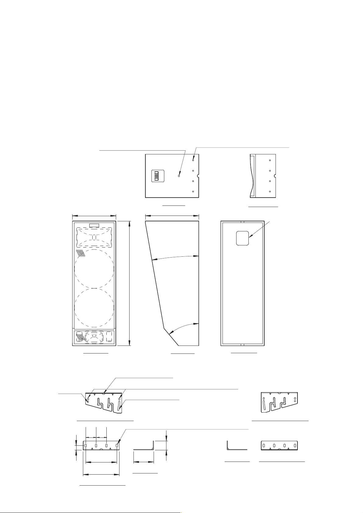
■ APPEARANCE AND DIMENSIONS (IN MM)
[Speaker system]
[Speaker mounting bracket A] [Speaker mounting bracket B]
Supplied M8 eyebolt mounting hole
288
827
Top view
354
10°
40°
Speaker mounting M8 hole (8 places)
Bottom view
Transformer installation
opening cover
Front view
Side view
Rear view
ø20 (Cable entry hole)
Axial hole
Speaker attaching side Speaker attaching side
30
69
69
207
240
Wall attaching side
9x13 oval hole (for direct speaker attachment)
Angle adjustment slot
11x21 oval hole (for inclined speaker attachment)
60
133
Side view
Side view
Wall attaching side
Page 3

■ MOUNTING THE SPEAKER ON THE WALL
1. Attach Speaker Brackets A and B to the upper and lower
parts of the wall using a total of eight bolts (four each per
bracket). (Note that the mounting position of Bracket A
or B differs depending on the direction in which the
speaker is inclined. Refer to the figures shown at the
lower right.)
Note
Bolts for attaching the brackets are not supplied with the
unit. Use appropriate types depending on the material and
construction of the wall.
2. Remove caps filling in eight screw holes in the unit's top
and bottom panels. Insert two of the eight supplied
speaker mounting bolts into two central holes in the top
panel, then tighten the bolts so that their heads stick out
5-6 mm, as shown in the figure at right.
Note
Take care that the speaker mounting bolt does not stick out
extremely.
3. Fit the mounted bolts into the two slots in the upper
bracket.
Memo
• Use the cable entry hole when the speaker cable needs
be left pulled out.
• It is also possible to lift up the speaker by means of an
eyebolt when installing it.
4. Fully inserting the bolts beyond the branch of the slot
temporarily secures the unit.
5. Insert the speaker mounting bolts into the remaining two
screw holes in the top panel. Use an oval hole for direct
speaker attachment located in the back of the bracket
when fitting the speaker's rear panel closely to the wall.
Use the angle adjustment slot and axial hole located in
the front of the bracket when adjusting angles.
6. Determine a horizontal installation angle, then tighten all
of the four speaker mounting bolts. (Note that if the
speaker's back is fitted closely to the wall, you cannot
change the installation angle.)
7. Similarly, secure the lower mounting bracket to the
speaker's bottom surface using four speaker mounting
bolts.
* Bracket arrangement when inclining the speaker to the
right.
** Bracket arrangement when inclining the speaker to the
left.
WARNING
Check to ensure that the mounting surface is strong
enough to stand the weight of a load before
beginning installation.
207
69 69
60
240
Speaker
mounting bolt
Wall mounting dimension
827
887
represents the surface to
which the bracket attaches.
Cap
Cap
Cableentryhole
5 – 6 mm
Eyeboltmountinghole
Mounting
bracket A *
Mounting
bracket B*
Axial hole
Mounting
bracket B**
Mounting
bracket A **
Angle
adjustment
slot
15°
Inclined speaker installation
(Maximum 15°)
Oval hole for
direct speaker
attachment
Direct speaker attachment
Page 4

ABOUT THE COMBINATION WITH OPTIONAL MATCHING TRANSFORMER
To install the MT-S0601 transformer in the speaker system,
remove the blank panel located at the back of the speaker
system. For the installation method, refer to the instruction manual
attached to the MT-S0601 transformer.
LARGE INPUT PROTECTOR
The T-650's short-distance tweeter has a circuit to protect the tweeter against extremely large input. (The connection of
the tweeter is cut off the instant the protection circuit is operated.) When the output volume level of high frequency sound
suddenly drops during use, this indicates the operation of the protection circuit. In such a case, turn down the amplifier
volume and wait until the protection circuit is automatically reset (2-20 seconds). When using the speaker again after the
circuit is reset, slightly decrease the amplifier volume than before.
Enclosure Bass reflex type
Power Handling Continuous pink noise: 120 W
Continuous program: 360 W
Rated impedance 8 Ω
Sound Pressure Level 100 dB (1 W,1 m)
Frequency Response 80 – 20,000 Hz
Crossover Frequency 1.2 kHz (passive network)
Speaker Component Low frequency: 25 cm cone speaker x 2
High frequency:
(for long distance use) CD horn fitted with compression driver (60 horizontal x 30 vertical)
(for short distance use) CD horn fitted with compression driver (90 horizontal x 40 vertical)
Input Terminal 2-pole M5 screw terminal, distance between barriers: 12.2 mm
Finish Enclosure: Coniferous plywood, black, semi-mat, urethane paint
Grille: Steel plate, black, semi-mat, acryl paint
Dimensions 288 (w) x 827 (h) x 354 (d) mm
Weight Speaker system: 20 kg, Mounting bracket: 2 kg
MT-S0601 High impedance High impedance
Primary terminal 100 V line 70 V line
83 Ω
–
60 W
170 Ω 60 W 30 W
330 Ω 30 W 15 W
670 Ω 15 W 7.5 W
Note: The design and specifications are subject to change without notice for improvement.
• Accessories
Speaker mounting bracket A ........................... 1
Speaker mounting bracket B ........................... 1
Speaker mounting bolt ..................................... 8
Eyebolt ............................................................. 1
SPECIFICATIONS
133-01-403-9B
URL: http://www.toa.jp/
Traceability Information for Europe (EMC directive 2004/108/EC)
Manufacturer:
TOA Corporation
7-2-1, Minatojima Nakamachi, Chuo-ku, Kobe, Hyogo,
Japan
Authorized representative:
TOA Electronics Europe GmbH
Suederstrasse 282, 20537 Hamburg,
Germany
 Loading...