

Page 1
Please follow the instructions in this manual to obtain the optimum results from this unit.
We also recommend that you keep this manual handy for future reference.
T-550SPEAKER SYSTEM
INSTRUCTION MANUAL
SAFETY PRECAUTIONS
• Be sure to read the instructions in this section carefully
before use.
• Make sure to observe the instructions in this manual as
the conventions of safety symbols and messages
regarded as very important precautions are included.
• We also recommend you keep this instruction manual
handy for future reference.
Safety Symbol and Message Conventions
Safety symbols and messages described below are used
in this manual to prevent bodily injury and property
damage which could result from mishandling. Before
operating your product, read this manual first so you are
thoroughly aware of the potential safety hazards as well as
understand the safety symbols and messages.
When Installing the Unit
• Install the unit only in a location that can structurally
support the weight of the unit and the mounting bracket.
Doing otherwise may result in the speaker falling down
and causing personal injury and/or property damage.
When the Unit is in Use
• Should the following irregularity be found during use,
immediately stop operating the unit and contact your
nearest TOA dealer. Make no further attempt to operate
the unit in this condition as this may cause fire or electric
shock.
· If you detect smoke or a strange smell coming from the
unit.
· If water or any metallic object gets into the unit
· If the unit falls, or the unit case breaks
· If it is malfunctioning (no tone sounds.)
When Installing the Unit
• When unpacking or moving a heavy speaker, be sure to
handle the unit with two or more persons. Falling or
dropping the speaker may cause personal injury and/or
property damage.
• Since installation requires specialized skills and
professional experience, always consult the shop from
where the unit was purchased before beginning
installation. If the speaker should fall, it could result in
electrical shocks or other personal injuries.
When the Unit is in Use
• Do not operate the speaker for an extended period of
time with the sound distorting. This is an indication of a
malfunction, which in turn can cause heat to generate
and result in a fire.
• Use only the specified matching transformer. If any other
matching transformer is used, it could cause damage to
the connected speaker, matching transformer itself, and
amplifier.
• Have the speaker unit checked periodically by the shop
from where it was purchased. Failure to do so may result
in corrosion or damage to the speaker or its mounting
bracket that could cause the speaker to fall, possibly
causing personal injury.
Indicates a potentially hazardous
situation which, if mishandled, could result in death or
serious personal injury.
WARNING
Indicates a potentially hazardous
situation which, if mishandled, could result in moderate or
minor personal injury, and/or property damage.
CAUTION
CAUTION
WARNING
Page 2
■ GENERAL DESCRIPTION
The T-550 speaker system is suited for installation as a supplementary speaker in indoor sports facilities or small and
intermediate halls.
■ FEATURES
• Highly-efficient 25 cm coaxial speaker component with a high handling power capacity.
• Heavy-duty construction protects unit against impacts from balls and other objects.
• Sturdy mounting brackets that permit unit to be temporarily secured.
• Can be positioned at any angle from 15° – 75° downward angle.
• Optional matching transformer permits unit to be used as a high-impedance speaker.
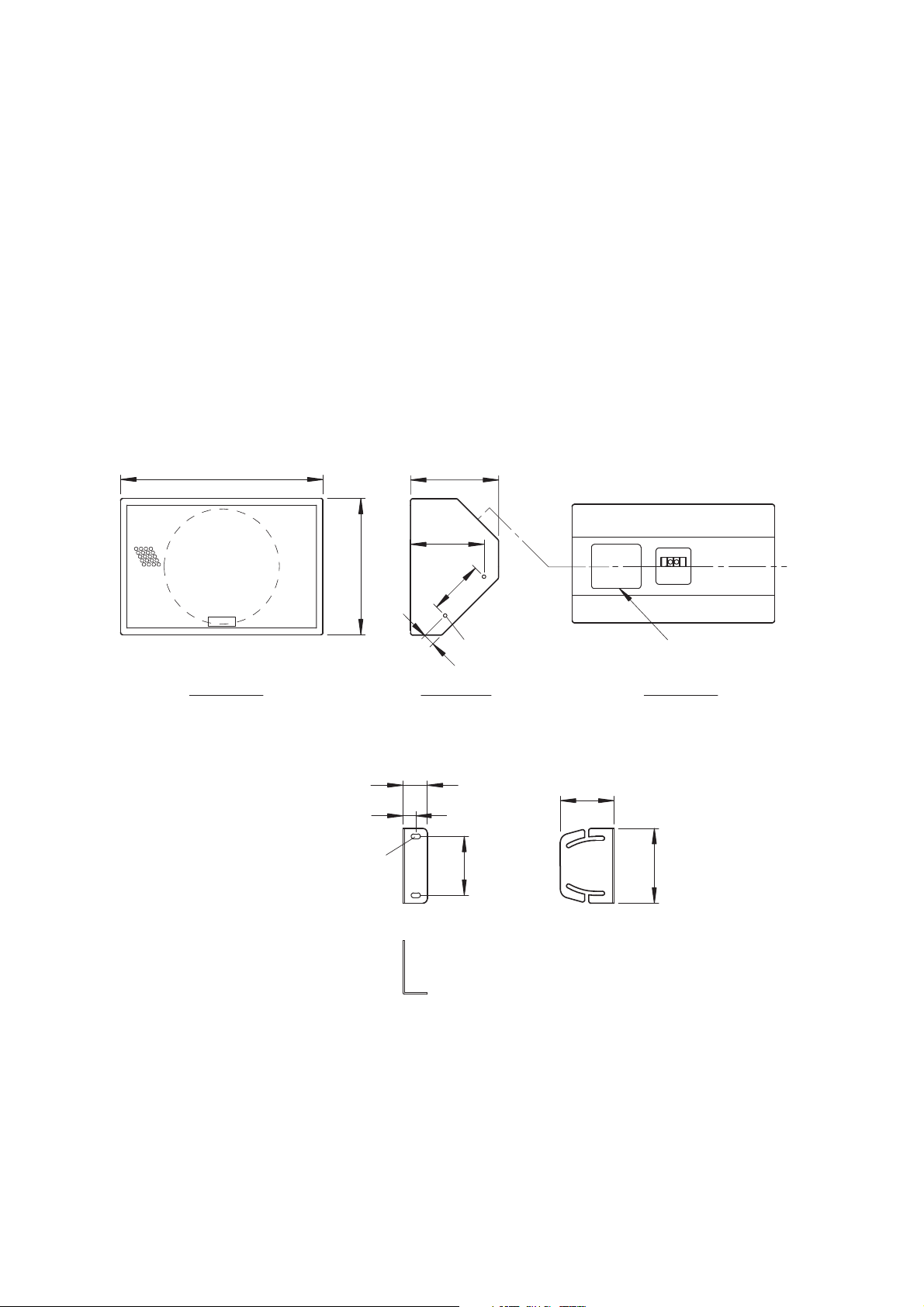
■ APPEARANCE AND DIMENSIONS (IN MM)
[Speaker system]
[Speaker mounting bracket]
460
11x21 oval holes for wall mounting (2 places)
310
55
29
26
200
167
125
M8 speaker mounting holes
(4 places)
Side panel Rear panelFront panel
134
Transformer installation
opening cover
122
170
Page 3

■ MOUNTING THE SPEAKER ON THE WALL
1. Attach two brackets to the wall using two bolts per
bracket.
WARNING
Check to ensure that the mounting surface is strong
enough to stand the weight of a load before
beginning installation.
Note
Bolts for attaching the brackets are not supplied with the
unit. Use appropriate types depending on the material and
construction of the wall.
2. Remove caps filling in four screw holes in the unit's
sides. Insert two of the four supplied speaker mounting
bolts into the upper holes in the sides, then tighten the
bolts so that their heads stick out 5-6 mm. Refer to the
figure below.
Note
Take care that the speaker mounting bolt does not stick
out extremely.
3. Fit the speaker mounting bolts into the upper slots of the
brackets.
4. Insert the remaining two speaker mounting bolts into the
screw holes in the unit's sides, and tighten them so that
their heads stick out 5-6 mm. (State of temporary fixing.)
5. Adjust the speaker's downward installation angle.
6. Tighten the four speaker mounting bolts and secure the
speaker.
518
170
460
134
represents the surface
to which the bracket
attaches.
55
Wall mounting dimension
318
33
15°
249
151
Speaker mounting bolt
5 – 6 mm
Cap
75°
Minimum downward
angle of 15°
270
45°
Direct speaker attachment to the wall
Maximum downward
angle of 75°
78
Page 4

Note: The design and specifications are subject to change without notice for improvement.
Enclosure Sealed type
Power Handling Continuous pink noise: 60 W
Continuous program: 180 W
Rated impedance 8 Ω
Sound Pressure Level 96 dB (1 W,1 m)
Frequency Response 100 – 20,000 Hz
Crossover Frequency 2.5 kHz (passive network)
Speaker Component 2-way coaxial unit
Low frequency: 25 cm cone speaker
High frequency: CD horn fitted with compression driver (60 horizontal x 60 vertical)
Input Terminal 2-pole M5 screw terminal, distance between barriers: 12.2 mm
Finish Enclosure: Coniferous plywood, black, semi-mat, urethane paint
Grille: Steel plate, black, semi-mat, acryl paint
Dimensions 460 (w) x 310 (h) x 200 (d) mm
Weight Speaker system: 9 kg, Mounting bracket: 2 kg
• Accessories
Speaker mounting bracket ............................... 2
Speaker mounting bolt ..................................... 4
ABOUT THE COMBINATION WITH OPTIONAL MATCHING TRANSFORMER
SPECIFICATIONS
To install the MT-S0601 transformer in the speaker system,
remove the blank panel located at the back of the speaker
system. For the installation method, refer to the instruction manual
attached to the MT-S0601 transformer.
MT-S0601 High impedance High impedance
Primary terminal 100 V line 70 V line
83 Ω
–
60 W
170 Ω 60 W 30 W
330 Ω 30 W 15 W
670 Ω 15 W 7.5 W
133-01-402-4B
URL: http://www.toa.jp/
Traceability Information for Europe (EMC directive 2004/108/EC)
Manufacturer:
TOA Corporation
7-2-1, Minatojima Nakamachi, Chuo-ku, Kobe, Hyogo,
Japan
Authorized representative:
TOA Electronics Europe GmbH
Suederstrasse 282, 20537 Hamburg,
Germany
 Loading...