

Page 1
OPERATING INSTRUCTIONS
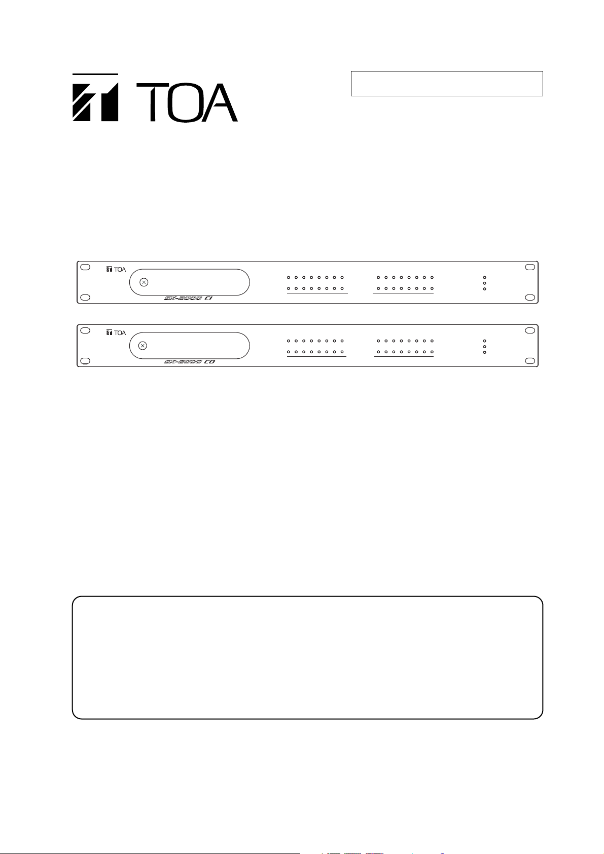
CONTROL INPUT UNIT
CONTROL OUTPUT UNIT
SX-2000CI
SX-2000CO
1. SAFETY PRECAUTIONS ........................... 2
2. GENERAL DESCRIPTION ......................... 3
3. NOMENCLATURE AND FUNCTIONS
3.1. SX-2000CI Control Input Unit ............... 4
3.2. SX-2000CO Control Output Unit .......... 6
4. CONNECTIONS
4.1. Removable Terminal Plug
Connection ........................................... 8
4.2. Connection Example ............................ 9
4.3. Power Supply Connections ................ 10
4.4. Control Input Connections
(SX-2000CI Only) ............................... 14
4.5. Control Output Connections
(SX-2000CO Only) ............................. 14
4.6. CI/CO Link Terminal Connections ...... 15
5. SETTINGS
5.1. Stand-Alone Mode Setting ................. 15
5.2. Priority Control Settings of the Control
Inputs (SX-2000CI Only) .................... 16
6. SPECIFICATIONS
6.1. SX-2000CI Control Input Unit ............. 19
6.2. SX-2000CO Control Output Unit ........ 20
Thank you for purchasing TOA's Control Input Unit and Control Output Unit.
Please carefully follow the instructions in this manual to ensure long, trouble-free use of your equipment.
TABLE OF CONTENTS
FOR STAND-ALONE MODE
Note
Two modes of operation are made available for the SX-2000CI and SX-2000CO: Normal mode
where the unit operates within the SX-2000 system and Stand-alone mode where the unit
operates independently of the SX-2000 system.
This book provides instruction when the SX-2000CI and SX-2000CO are used in stand-alone
mode.
When using them in normal operation mode, refer to the instruction manual enclosed with the
SX-2000SM System Manager of the SX-2000 series.
SX-2000CI
192103114125136147158
SX-2000CO
192103114125136147158
172518261927202821292230233124
16
CONTROL INPUT
172518261927202821292230233124
16
CONTROL OUTPUT
32
32
POWER
CPU OFF
FAULT
CONTROL INPUT UNIT SX-2000CI
POWER
CPU OFF
FAULT
CONTROL OUTPUT UNIT SX-2000CO
Page 2
2
When Installing the Unit
• Do not expose the unit to rain or an environment
where it may be splashed by water or other liquids,
as doing so may result in fire or electric shock.
• Use the unit only with the voltage specified on the
unit. Using a voltage higher than that which is
specified may result in fire or electric shock.
• Since the unit is designed for in-door use, do not
install it outdoors. If installed outdoors, the aging of
parts causes the unit to fall off, resulting in personal
injury. Also, when it gets wet with rain, there is a
danger of electric shock.
When the Unit is in Use
• Should the following irregularity be found during
use, immediately switch off the power, disconnect
the power supply plug from the AC outlet and
contact your nearest TOA dealer. Make no further
attempt to operate the unit in this condition as this
may cause fire or electric shock.
· If you detect smoke or a strange smell coming
from the unit.
· If water or any metallic object gets into the unit
· If the unit falls, or the unit case breaks
· If it is malfunctioning (no tone sounds.)
• To prevent a fire or electric shock, never open nor
remove the unit case as there are high voltage
components inside the unit. Refer all servicing to
qualified service personnel.
• Do not place cups, bowls, or other containers of
liquid or metallic objects on top of the unit. If they
accidentally spill into the unit, this may cause a fire
or electric shock.
When Installing the Unit
• Avoid installing the unit in humid or dusty locations,
in locations exposed to the direct sunlight, near the
heaters, or in locations generating sooty smoke or
steam as doing otherwise may result in fire or
electric shock.
• SX-2000CI and SX-2000CO are designed
exclusively to be mounted in an equipment rack.
Be sure to follow the instructions below when rackmounting the unit. Failure to do so may cause a fire
or personal injury.
· Install the equipment rack on a stable, hard floor.
Fix it with anchor bolts or take other arrangements
to prevent it from falling down.
· When connecting the power cord of the DC
power supply panel for the SX-2000CI/CO to an
AC outlet, ensure that the total load current never
exceeds the AC outlet’s allowable current
capacity.
· The supplied rack-mounting screws can be used
for the TOA equipment rack only. Do not use
them for other racks.
When the Unit is in Use
• Use the specified DC power supply unit AD-011 or
AD-031B for the unit. Note that the use of other DC
power supply unit may cause a fire.
1. SAFETY PRECAUTIONS
• Before installation or use, be sure to carefully read all the instructions in this section for correct and safe
operation.
• Be sure to follow all the precautionary instructions in this section, which contain important warnings and/or
cautions regarding safety.
• After reading, keep this manual handy for future reference.
Safety Symbol and Message Conventions
Safety symbols and messages described below are used in this manual to prevent bodily injury and property
damage which could result from mishandling. Before operating your product, read this manual first and
understand the safety symbols and messages so you are thoroughly aware of the potential safety hazards.
WARNING
Indicates a potentially hazardous situation which, if mishandled, could
result in death or serious personal injury.
Indicates a potentially hazardous situation which, if mishandled, could
result in moderate or minor personal injury, and/or property damage.
WARNING
CAUTION
CAUTION
Page 3

3
2. GENERAL DESCRIPTION
The SX-2000CI Control Input Unit is equipped with 32 control input channels, and the SX-2000CO Control
Output Unit with 32 control output channels, allowing various operations to be performed by connecting
external equipment.
One each of the SX-2000CI and SX-2000CO must be used in combination. Connecting the CI/CO link data
terminals of each unit to one another permits the contact data of multiple channels to be transmitted to the
remote locations with simple wiring.
The front-mounted indicators of each unit show the control input status or control output status.
The SX-2000CI and SX-2000CO are 1U-size* units that can be mounted in an EIA equipment rack. It has 2
power supply inputs, one of which can be connected to a backup power source to protect against power
failures. The SX-2000CI has a function to supply a stabilized 24 V DC.
Priority control of the control input can be performed by making settings at the SX-2000CI.
*1U size = 44.5 mm (standard size)
Page 4
4
3. NOMENCLATURE AND FUNCTIONS
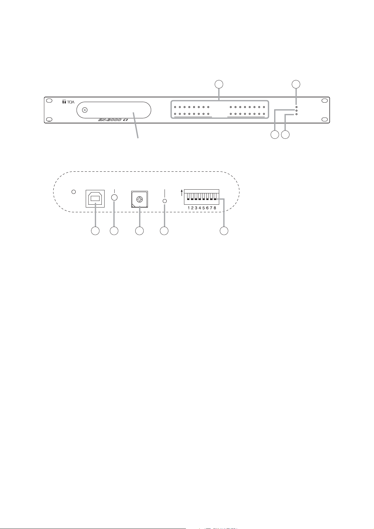
3.1. SX-2000CI Control Input Unit
[Front]
1. Control Input Indicators
[CONTROL INPUT 1 – 32] (Green)
Light when the corresponding control inputs are
turned ON.
2. Power Indicator [POWER] (Blue)
Lights when the power is switched on.
3. CPU OFF Indicator [CPU OFF] (Red)
This indicator is not used.
4. FAULT Indicator [FAULT] (Yellow)
Lights when communications with the connected
SX-2000CO are interrupted.
5. USB Port [USB]
This port is not used.
6. RUN Indicator [RUN] (Green)
Normally flashes continuously.
7. ID Switch [ID NUMBER]
This switch is not used.
Always set to "0."
Note
This switch is set to "0" by default.
8. Reset Key [RESET]
Pressing this key restarts the SX-2000CI.
9. DIP Switch [SETTING]
• Switch 1
Sets operation mode. (See p. 15.)
ON: Operates in stand-alone mode.
OFF: Operates in normal mode.
• Switch 2
This switch is not used.
• Switches 3, 4
Perform priority control settings of the control
inputs by combined settings of Switches 3 and 4.
(See p. 16.)
• Switches 5 – 8
These switches are not used.
Note
Switches 1 – 8 are set to the OFF position by
default.
Protective cover
Inside of the protective cover
ID NUMBER RESET
9
8
A
7
B
6
C
5
D
4
E
3
F
2
0
1
5 6 7 8 9
1
192103114125136147158
16
CONTROL INPUT
SETTINGUSB RUN
ON
172518261927202821292230233124
32
3 4
2
POWER
CPU OFF
FAULT
CONTROL INPUT UNIT SX-2000CI
Page 5
5
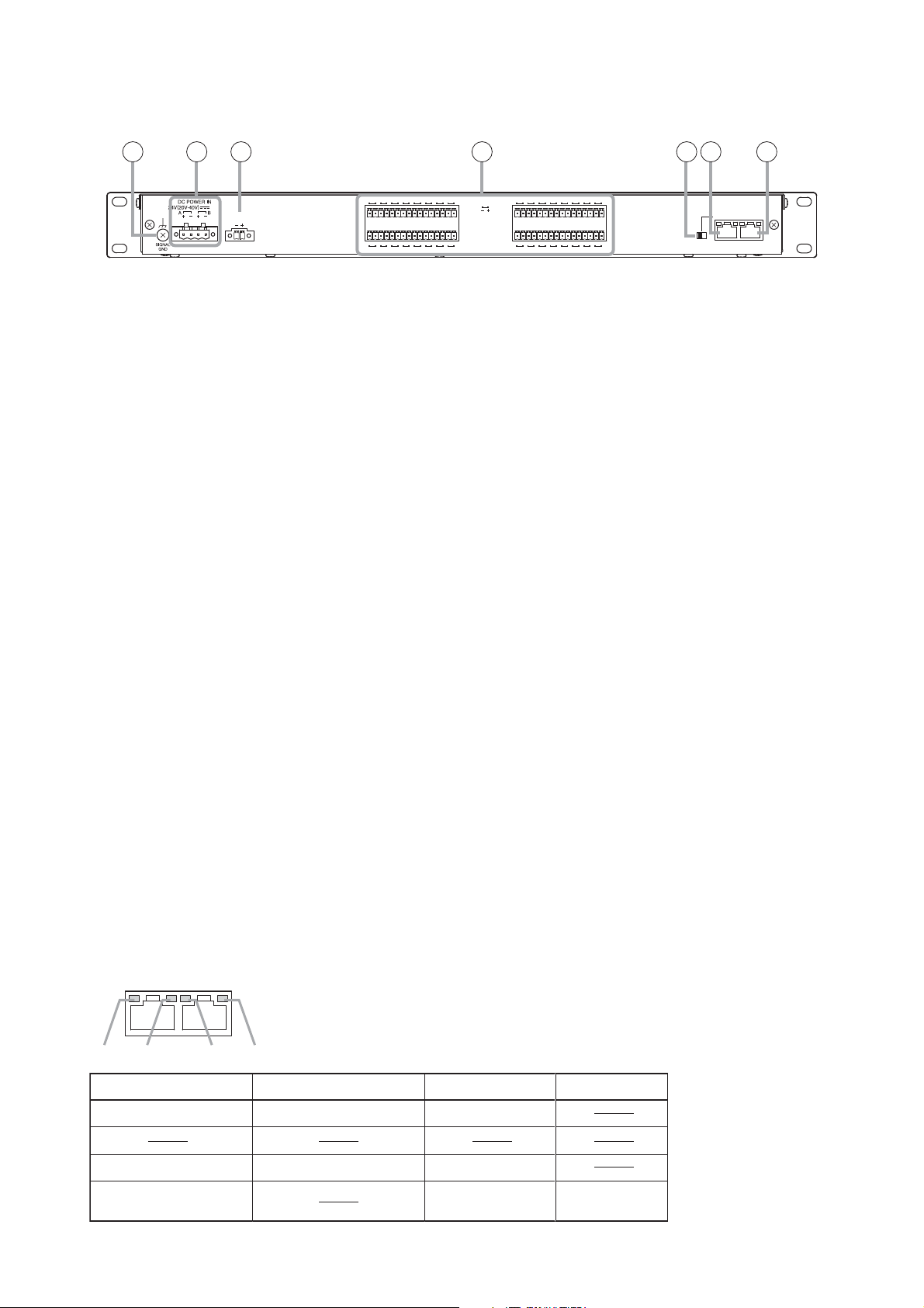
[Rear]
10. Functional Earth Terminal [SIGNAL GND]
Hum noise may be generated when external
equipment is connected to the unit. Connecting
this terminal to the functional earth terminal of
the external equipment may reduce the hum
noise.
Note: This terminal is not for protective earth.
11. DC Power Input Terminal [DC POWER IN]
Connect an optional AD-011 or AD-031B DC
Power Supply Panel to this terminal.
Select the appropriate panel taking into
consideration the total current consumption of all
equipment to be connected to the power supply
unit. (See p. 10.)
When not using a redundant power system*,
connect the [+] terminal of input A to the [+]
terminal of input B, and the [–] terminal of input A
to the [–] terminal of input B.
(See p. 11 and p. 13.)
* A method of connecting separate power
sources to each power input or connecting the
commercial power supply and backup power
supply separately to each power input to
prevent the system from going down when a
cable is broken or power fails.
12. 24 V DC Output Terminal [DC 24 V OUT]
This terminal supplies 24 V DC, max. 100 mA to
connected external equipment.
13. Control Input Terminals
[CONTROL INPUT 1 – 32]
Photo coupler inputs. A current of approximately
2 mA flows when shorted, and the voltage
becomes approximately 24 V DC when opened.
Activating the control input terminal causes the
control output terminal with the same channel
number (SX-2000CO) to close (provides make
contact).
14. CI/CO Link Through Switch [ON/OFF]
Normally, set this switch to the OFF position.
Note
This switch is set to "OFF" by default.
15. CI/CO Link Through Terminal
[CI/CO LINK THROUGH]
This terminal is not used.
Refer to the table below for the indicators'
functions and status.
16. CI/CO Link Data Terminal [CI/CO LINK DATA]
Connect this terminal to the CI/CO Link Terminal
of the SX-2000CO.
Refer to the table below for the indicators'
functions and status.
[Indicators' functions and status of the CI/CO Link Through/Data terminals]
10
12 14 15 1613
11
DC 24V OUT
MAX. 0.1A
1718192021222324
CONTROL
INPUT
2526272829303132
12345678
910111213141516
ONOFF
CI/CO LINK
THROUGH
DATA
CI/CO LINK
THROUGH
1 234
1. CI/CO LINK status Communication start Communication stop
2.
DATA
Functions LED On or Flashing (green) LED Off LED On (orange)
3. CI/CO LINK status Communication start Communication stop
4. CI/CO LINK connection
confirmation
Unconnected Connected
Page 6
6
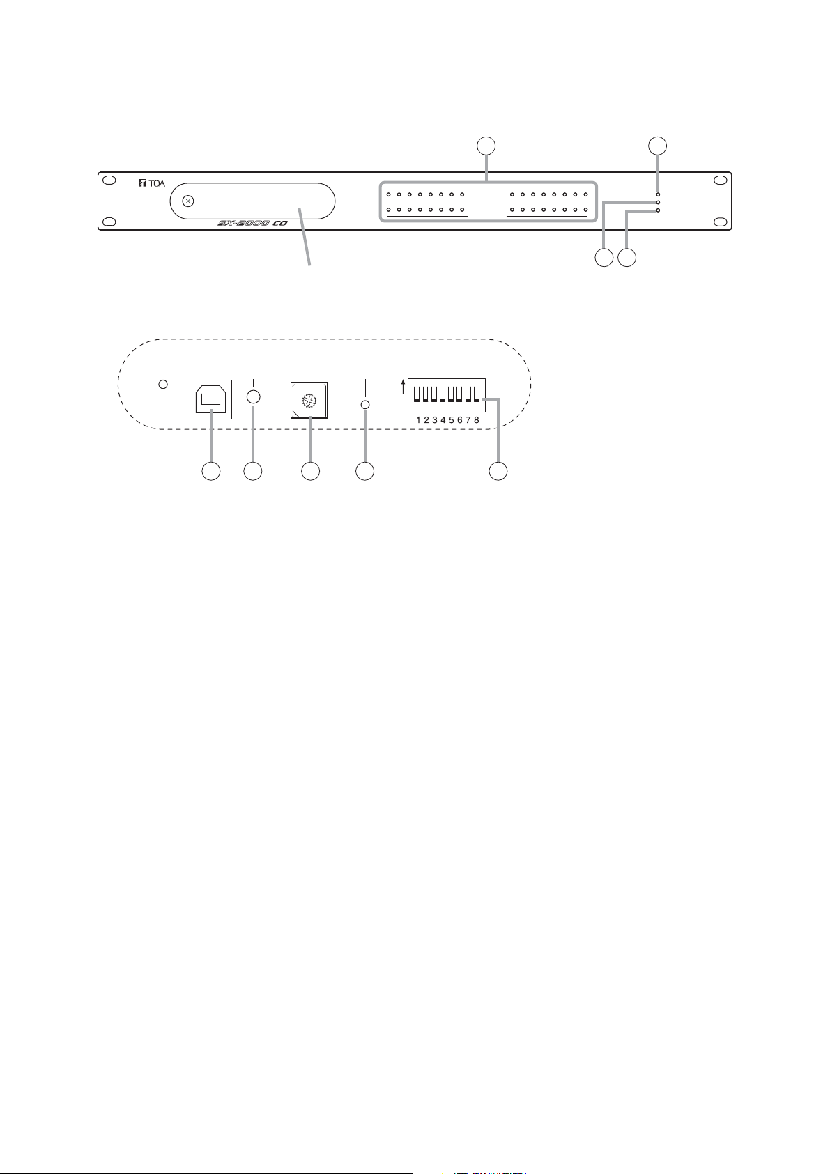
3.2. SX-2000CO Control Output Unit
[Front]
1. Control Output Indicators
[CONTROL OUTPUT 1 – 32] (Green)
Light when the corresponding control outputs are
turned ON.
2. Power Indicator [POWER] (Blue)
Lights when the power is switched on.
3. CPU OFF Indicator [CPU OFF] (Red)
This indicator is not used.
4. FAULT Indicator [FAULT] (Yellow)
Lights when communications with the connected
SX-2000CI are interrupted.
5. USB Port [USB]
This port is not used.
6. RUN Indicator [RUN] (Green)
Normally flashes continuously.
7. ID Switch [ID NUMBER]
This switch is not used.
Always set to "1."
Note
This switch is set to "1" by default.
8. Reset Key [RESET]
Pressing this key restarts the SX-2000CO.
9. DIP Switch [SETTING]
• Switch 1
Sets operation mode. (See p. 15.)
ON: Operates in stand-alone mode.
OFF: Operates in normal mode.
• Switches 2 – 8
These switches are not used.
Note
Switches 1 – 8 are set to the OFF position by
default.
Protective cover
Inside of the protective cover
USB RUN
ID NUMBER
9
8
A
7
B
6
C
5
D
4
E
3
F
2
0
1
RESET
5 6 7 8 9
1
192103114125136147158
16
CONTROL OUTPUT
SETTINGON
172518261927202821292230233124
32
CONTROL OUTPUT UNIT SX-2000CO
3 4
2
POWER
CPU OFF
FAULT
Page 7

7
[Rear]
10. Functional Earth Terminal [SIGNAL GND]
Hum noise may be generated when external
equipment is connected to the unit. Connecting
this terminal to the functional earth terminal of
the external equipment may reduce the hum
noise.
Note: This terminal is not for protective earth.
11. DC Power Input Terminal [DC POWER IN]
Connect an optional AD-011 or AD-031B DC
Power Supply Panel to this terminal.
Select the appropriate panel taking into
consideration the total current consumption of all
equipment to be connected to the power supply
unit. (See p. 10.)
When not using a redundant power system*,
connect the [+] terminal of input A to the [+]
terminal of input B, and the [–] terminal of input A
to the [–] terminal of input B.
(See p. 11 and p. 13.)
When driving the unit with the power supply unit
connected to the SX-2000CI, connect the power
supply to this terminal via an optional RM-200RJ
Terminal Unit.
(See p. 12 and p. 13.)
* A method of connecting separate power
sources to each power input or connecting the
commercial power supply and backup power
supply separately to each power input to
prevent the system from going down when a
cable is broken or power fails.
12. Control Output Terminals
[CONTROL OUTPUT 1 – 32]
Relay make contact outputs.
Activating the control input terminal of the SX2000CI causes the control output terminal with
the same channel number to close.
Each contact capacity is rated at 40 V DC for
withstand voltage, and 2 mA – 300 mA for
control current.
13. CI/CO Link Through Switch [ON/OFF]
Normally, set this switch to the OFF position.
Note
This switch is set to "OFF" by default.
14. CI/CO Link Through Terminal
[CI/CO LINK THROUGH]
This terminal is not used.
Refer to the table below for the indicators'
functions and status.
15. CI/CO Link Data Terminal [CI/CO LINK DATA]
Connect this terminal to the CI/CO Link Terminal
of the SX-2000CI.
Power to operate the unit cannot be supplied
through this terminal.
Refer to the table below for the indicators'
functions and status.
[Indicators' functions and status of the CI/CO Link Through/Data terminals]
10
11
14 151312
1718192021222324
CONTROL
12345678
OUTPUT
CNCNO
CI/CO LINK
THROUGH
DATA
ONOFF
9101112131415162526272829303132
CI/CO LINK
THROUGH
1 234
1. CI/CO LINK status Communication start Communication stop
2.
3. CI/CO LINK status Communication start Communication stop
4. CI/CO LINK connection
confirmation
DATA
Functions LED On or Flashing (green) LED Off LED On (orange)
Unconnected Connected
Page 8

8
4. CONNECTIONS
4.1. Removable Terminal Plug Connection
Notes
• Do not use a micro screwdriver. Sufficient torque is not given to the screws when tightening them, and
connections may not be secured.
• Avoid soldering stranded or shielded cable, as contact resistance may increase when the cable is tightened
and the solder is crushed, possibly resulting in an excessive rise in joint temperatures.
• When connecting 2 cables or a shielded cable to a single terminal,
use a ferrule terminal with an insulation sleeve to crimp the cables
because such cable conductors could become loose.
Recommended ferrule terminals for signal cables
(made by Phoenix Contact)
Recommended ferrule terminals for power supply cables
(made by Phoenix Contact)
Crimping tool: CRIMPFOX UD6-4 (made by Phoenix Contact)
Wiring procedures
Procedures below are for the removable terminal plug with fixing screws.
Step 1. Wiring the supplied removable terminal plug.
1-1. Loosen the terminal screws to insert the wire.
1-2. Tighten the terminal screws.
Ensure that the wire does not break free
when pulled. If the wire does pull free, repeat
the connection procedure from the start.
Step 2. Insert the wired terminal plug into the
corresponding terminal block in the unit's rear
panel.
Step 3. Tighten the fixing screw.
Notes
• Do not reverse Steps 1 and 2 above. Force is applied to the connected receptacle pins while tightening the
terminal screw and they may be damaged, resulting in bad connector contact.
• When detaching the terminal plug, pull it straight out. Pulling it out at an angle may cause the terminal plug
or terminal block to break.
Cable sheath to trim
* Expose 8 mm or more when using the
above ferrule terminal, and cut off an extra
conductor protruding from the sleeve.
Model Number a l
AI 0,34-8 TQ
AI 0,5-8 WH
2 mm
2.5 mm
b
0.8 mm
1.1 mm
12.5 mm
14 mm
1
2
l
8 mm
8 mm
Model Number a
AI 1,5-8 BK
AI-TWIN 2 x 1,5-8 BK 6.6 mm
a
3.4 mm
1
2
a
3.6 mm
b
1.8 mm
1
l
14 mm
16 mm2.3 mm
2
l
8 mm
8 mm
Insulation sleeve
a
Insulation sleeve
1
a
a
Contact section
2
l
1
l
Contact section
2
2
l
1
l
bb
Solid cable and stranded cable
7 mm*
Shielded cable
15 mm
7 mm*
To tighten
Terminal screw
Straight slot screwdriver
To loosen
Removable terminal plug
Fixing screw
Page 9

9
4.2.1. Connection example 1
Connect each 2 power supply units to the SX-2000CI and SX-2000CO separately. (See p. 10 and 15.)
4.2.1. Connection example 2
Connect each one power supply unit to the SX-2000CI and SX-2000CO separately. (See p. 11 and 15.)
4.2.1. Connection example 3
Connect 2 power supply units to the SX-2000CI only via Terminal unit. (See p. 11.)
4.2.1. Connection example 4
Connect a single power supply unit to the SX-2000CI only via Terminal unit. (See p. 13.)
4.2. Connection Example
There are 4 connection configurations depending on the DC power supply and CI/CO link connections.
Note: For the detailed information on the connections of power supply unit and CI/CO links, refer to the page
indicated at the end of each "Connection example."
SX-2000CI
192103114125136147158
16
172518261927202821292230233124
CONTROL INPUT
POWER
CPU OFF
32
FAULT
CONTROL INPUT UNIT SX-2000CI
Redundant power supply system*
Program timer
Power supply unit (1)
Power supply unit (2)
SX-2000CO
192103114125136147158
A method of connecting separate power sources to each power
*
16
CONTROL OUTPUT
172518261927202821292230233124
32
POWER
CPU OFF
FAULT
CONTROL OUTPUT UNIT SX-2000CO
input or connecting the commercial power supply and backup
Digital announce machine
Power supply unit (3)
Power supply unit (4)
power supply separately to each power input to prevent the
system from going down when a cable is broken or power fails.
SX-2000CI
192103114125136147158
SX-2000CO
192103114125136147158
16
16
CONTROL INPUT
CONTROL OUTPUT
172518261927202821292230233124
172518261927202821292230233124
32
32
POWER
CPU OFF
FAULT
CONTROL INPUT UNIT SX-2000CI
POWER
CPU OFF
FAULT
CONTROL OUTPUT UNIT SX-2000CO
Program timer
Power supply unit (1)
Digital announce machine
Power supply unit (2)
SX-2000CI
192103114125136147158
Terminal unit
Supplies power from
the SX-2000CI side
Terminal unit
16
CONTROL INPUT
172518261927202821292230233124
POWER
CPU OFF
32
FAULT
CONTROL INPUT UNIT SX-2000CI
Redundant power
supply system
Program timer
Power supply unit (1)
Power supply unit (2)
SX-2000CO
192103114125136147158
16
CONTROL OUTPUT
172518261927202821292230233124
32
POWER
CPU OFF
FAULT
CONTROL OUTPUT UNIT SX-2000CO
Digital announce machine
SX-2000CI
192103114125136147158
Terminal unit
Supplies power from
the SX-2000CI side
Terminal unit
SX-2000CO
192103114125136147158
16
16
CONTROL INPUT
CONTROL OUTPUT
172518261927202821292230233124
172518261927202821292230233124
32
32
POWER
CPU OFF
FAULT
CONTROL INPUT UNIT SX-2000CI
POWER
CPU OFF
FAULT
CONTROL OUTPUT UNIT SX-2000CO
Program timer
Power supply unit
Digital announce machine
: CI/CO link
: Power cable : CPEV cable : Control line
Page 10

10
4.3. Power Supply Connections
Use an optional AD-011 or AD-031B DC Power Supply Panel to this terminal. Select the appropriate panel
taking into consideration the total current consumption of all equipment to be connected to the power supply
unit.
4.3.1. Connection for Example 1
Connect each 2 power supply units to the SX-2000CI and SX-2000CO separately as follows. Connect one
power supply unit to A channel of the DC power input terminal and the other power supply unit to the B
channel of the DC power input terminal on the SX-2000CI. Connect the power supply units to the SX-2000CO
in the same manner.
Even if one of the 2 units fails or its power supply line is broken, power is still supplied from the other unit,
preventing the system from going down.
Note: When using the AD-031B DC power supply panel (optional), make connections in the same manner.
AD-011 DC power supply panel
24VDC OUT 24VDC IN
Cable: AWG14 – 18
AD-011
24VDC OUT 24VDC IN
Cable: AWG14 – 18
AD-011
24VDC OUT 24VDC IN
SX-2000CI
DC 24V OUT
MAX. 0.1A
SX-2000CO
1718192021222324
CONTROL
INPUT
2526272829303132
DC power input terminal
4P removable terminal plug
(supplied with the SX-2000CI)
STP Category 5 straight cable
(with RJ45 connectors)
1718192021222324
DC power input terminal
12345678
910111213141516
CI/CO LINK
THROUGH
DATA
ONOFF
CONTROL
12345678
OUTPUT
CNCNO
CI/CO LINK
THROUGH
DATA
ONOFF
9101112131415162526272829303132
Cable: AWG14 – 18
AD-011
4P removable terminal plug
(supplied with the SX-2000CO)
24VDC OUT 24VDC IN
Cable: AWG14 – 18
Page 11

11
4.3.2. Connection for Example 2
Supply the power from each one power supply panel to the SX-2000CI and SX-2000CO separately.
Connect the (+) terminal of channel A to the (+) terminal of channel B, and the (–) terminal of channel A to the
(–) terminal of channel B.
Note
Use a ferrule terminal when connecting
2 cables to a single terminal. (See p. 8.)
4.3.3. Connection for Example 3
Both the SX-2000CI and SX-2000CO can be driven by connecting 2 power supply panels to the SX-2000CI
only.
Connect the DC power input terminals of the SX-2000CI to those of the SX-2000CO and the CI/CO link data
terminals of the SX-2000CI to those of the SX-2000CO via the RM-200RJ Terminal Unit (optional).
(See the next page.)
When installing the SX-2000CI and SX-2000CO separately from each other, the power supply panel does not
need to have at each unit by making connection in this manner.
Note
When connecting the power supply panel to one of the equipment, be sure to connect it to the SX-2000CI
side.
If it is connected to the SX-2000CO side, the maximum cable length between the SX-2000CI and SX-2000CO
may be reduced.
[Maximum cable length]
The maximum cable length between the SX-2000CI and SX-2000CO varies depending on the conductor
diameter of the CPEV cable used between the RM-200RJs.
The following table shows the conductor diameter of the CPEV cable vs. maximum cable length when the
power is supplied from the SX-2000CI side.
Note: When using the AD-031B DC power supply panel (optional), make connections in the same manner.
AD-011 DC power supply panel
24VDC OUT 24VDC IN
Cable: AWG14 – 18
AD-011
24VDC OUT 24VDC IN
Cable: AWG14 – 18
SX-2000CI
DC 24V OUT
MAX. 0.1A
SX-2000CO
1718192021222324
CONTROL
INPUT
2526272829303132
12345678
910111213141516
DC power input terminal
STP Category 5 straight cable
(with RJ45 connectors)
4P removable terminal plug
(supplied with the SX-2000CI)
1718192021222324
DC power input terminal
4P removable terminal plug
(supplied with the SX-2000CO)
12345678
9101112131415162526272829303132
CONTROL
OUTPUT
CI/CO LINK
THROUGH
DATA
ONOFF
CNCNO
CI/CO LINK
THROUGH
DATA
ONOFF
Conductor diameter
AWG 22
AWG 19
AWG 16
AWG 19 x 3 pair-CPEV (2 pairs for DC and 1 pair for data)
AWG 16 x 3 pair-CPEV (2 pairs for DC and 1 pair for data)
Maximum cable length
160 m
320 m
570 m
640 m
800 m
Page 12

12
[Connections]
It is recommended to use an optional RM-200RJ Terminal Unit that serves wiring conversion between the
CPEV cable and STP Category 5 straight cable (with RJ45 connectors). Connect the CPEV cable between
the same terminals of both RM-200RJ units pairing cables 3 with 6, 4 with 5, and 7 with 8 as shown below.
Terminals 4 and 5 serve to supply power to B channel.
Note: When using the AD-031B DC power supply panel (optional),
make connections in the same manner.
Note
Terminals 1 and 2
cannot be used for
power supply line.
SX-2000CO
DC power
input terminal
AWG14 – 18
STP Category 5 straight cable
(with RJ45 connectors)
AWG14 – 18
SX-2000CI
DC power
input terminal
CI/CO link
data terminal
5
4
7
8
CI/CO link
data terminal
RM-200RJ
terminal unit
RM-200RJ
4
5
3
6
7
8
Shield
Over 3-pair shielded
CPEV cable (main cable)
AWG14 – 18
AD-011
DC power supply panel
24VDC OUT 24VDC IN
AD-011
24VDC OUT 24VDC IN
5
4
STP Category 5 straight cable
(with RJ45 connectors)
7
8
Note: The RM-200RJ can be installed on a desk or to a wall.
AWG14 – 18
4
5
3
6
7
8
Shield
[RM-200RJ Mounting dimensions]
84
75
44.5
116
44.513.5
Unit: mm
Page 13

13
4.3.4. Connection for Example 4
Drive both the SX-2000CI and SX-2000CO by connecting a single power supply panel to the SX-2000CI only.
Connect the DC power input terminals of the SX-2000CI to those of the SX-2000CO and the CI/CO link data
terminals of the SX-2000CI to those of the SX-2000CO via the RM-200RJ Terminal Unit (optional).
When installing the SX-2000CI and SX-2000CO separately from each other, the power supply panel does not
need to have at each unit by making connection in this manner.
Note
When connecting the power supply unit to one of the equipment, be sure to connect it to the SX-2000CI side.
If it is connected to the SX-2000CO side, the maximum cable length between the SX-2000CI and SX-2000CO
may be reduced.
For the conductor diameter of the CPEV cable vs. maximum cable length when the power is supplied from the
SX-2000CI side, refer to the table on p. 11.
[Connections]
It is recommended to use an optional RM-200RJ Terminal Unit that serves wiring conversion between the
CPEV cable and STP Category 5 straight cable (with RJ45 connectors). Connect the CPEV cable between
the same terminals of both RM-200RJ units pairing cables 3 with 6, and 7 with 8 as shown below.
SX-2000CO
DC power
input terminal
STP Category 5 straight cable
(with RJ45 connectors)
AWG14 – 18
SX-2000CI
DC power
input terminal
CI/CO link
data terminal
7
8
CI/CO link
data terminal
RM-200RJ terminal unit
RM-200RJ
3
6
7
8
Shield
Over 2-pair shielded
CPEV cable
(main cable)
STP Category 5 straight cable
(with RJ45 connectors)
AWG14 – 18
AD-011 DC power supply panel
24VDC OUT 24VDC IN
AWG14 – 18
3
6
7
8
7
8
Shield
Notes
The RM-200RJ can be installed on a desk or to a wall.
•
Refer to the RM-200RJ mounting dimensions on the
previous page.
When using the AD-031B DC power supply panel
•
(optional), make connections in the same manner.
Page 14

14
4.4. Control Input Connections (SX-2000CI Only)
This connection example allows timer-activated automatic broadcasts.
When the TT-104B's preprogrammed time is reached, the SX-2000CI receives a control output signal (make
contact) from the TT-104B and activates preset broadcast patterns.
4.5. Control Output Connections (SX-2000CO Only)
This example shows the connection method to remotely activate the external sound source equipment.
When a broadcast is started, the SX-2000CO provides a make contact to activate the EV-350R.
TT-104B
program timer
Cable: AWG22 – 28
twisted pair cable
SX-2000CI
DC 24V OUT
MAX. 0.1A
16P removable terminal plug
(supplied with the SX-2000CI)
OUTPUT CHANNEL (24 V DC 0.5 A)
OUTPUT CHANNEL (24 V DC 0.5 A)
1718192021222324
CONTROL
INPUT
2526272829303132
Control input terminals
CAUTION
BE SURE TO SET
THIS SWITCH TO “ON”
AFTER INSTALLATION
12345678
910111213141516
ON
OFFONOFF
MEMORY
CHANNEL
BACK UP
ASSIGNMENT
CI/CO LINK
THROUGH
DATA
ONOFF
Open voltage: 24 V DC
Short-circuit current: 2 mA
Control output terminals
SX-2000CO
Cable: AWG22 – 28
twisted pair cable
Activation control input terminal 1
EV-350R
Digital announcer
1718192021222324
COM terminal
CONTROL
12345678
OUTPUT
CNCNO
CI/CO LINK
THROUGH
DATA
ONOFF
9101112131415162526272829303132
Withstand voltage: 40 V DC
Control current: 2 – 300mA
6P removable terminal plug
(supplied with the SX-2000CO)
OUTPUT
UNBAL.
AUX INPUT
UNBAL.
Activation control input terminal 2
Page 15

15
4.6. CI/CO Link Terminal Connections (Applies to the example 1 or 2 on p. 9.)
Connect the same CI/CO link data terminals of both the SX-2000CI and SX-2000CO.
For the connection cable, use a STP Category 5 twisted pair cable (with RJ45 connectors).
The SX-2000CI and SX-2000CO can be connected using the shielded CPEV cable (1-pair for data line) via
the optional RM-200RJ Terminal unit.
Note
Total cable length connecting CI/CO link terminals within the system must be kept shorter than 800 m.
5. SETTINGS
5.1. Stand-Alone Mode Setting
Step 1. Remove the protective cover on the SX-2000CI/CO's front panel by
unscrewing it with a Phillips screwdriver.
Step 2. Set the DIP switch 1 on the SX-2000CI/CO to ON.
Note: Switch 1 is set to OFF by default.
CI/CO link data terminal
SX-2000CI
DC 24V OUT
MAX. 0.1A
1718192021222324
CONTROL
INPUT
2526272829303132
12345678
910111213141516
THROUGH
ONOFF
CI/CO LINK
CI/CO LINK
THROUGH
DATA
ONOFF
DATA
STP Category 5 straight cable
(with RJ45 connectors)
CI/CO link through switch: OFF
(Factory preset: OFF)
SX-2000CO
1718192021222324
CI/CO link data terminal
CI/CO LINK
CONTROL
12345678
THROUGH
9101112131415162526272829303132
ONOFF
DATA
OUTPUT
CNCNO
CI/CO LINK
THROUGH
DATA
ONOFF
CI/CO link through switch: OFF
(Factory preset: OFF)
SX-2000CI
Screw
Protective cover
Note: Fragmentary view of the SX-2000CI. This view is the same for the SX-2000CO.
Inside of the protective cover
USB RUN
ID NUMBER
9
8
A
7
B
6
C
5
D
4
E
3
F
2
0
1
RESET
Reset key
SETTINGON
DIP switches
SETTINGON
Page 16

16
Step 4. Press the Reset key on the SX-2000CI/CO's front panel.
The SX-2000CI/CO is reactivated.
Step 5. Replace the protective cover.
Note
When operating the SX-2000CI/CO in stand-alone mode, do not connect it to the SX-2000AO or SX-2100AO
as doing so may cause system malfunction.
5.2. Priority Control Settings of the Control Inputs (SX-2000CI Only)
Priority control of the control inputs can be performed by combined settings of the DIP switches 3 and 4 inside
the protective cover (see the previous page) on the SX-2000CI's front panel.
Step 3. Set the link through switch on the SX-2000CI/CO's rear panel to the OFF position.
Note: The CI/CO link through switch is set to OFF by default.
Notes
• If you change the DIP switch setting, be sure to press the Reset key inside the protective cover to restart the
SX-2000CI.
• Control inputs act as such that they have been closed in numerical order of terminal numbers after the SX2000CI is switched on or restarted with these inputs closed in any order.
In this case, the highest priority is assigned to the control input of the largest terminal number when the
priority control type is "Last-in-first-out," and to the control input of the smallest terminal number when "Firstin-first-out."
SX-2000CI rear
DC 24V OUT
MAX. 0.1A
1718192021222324
CONTROL
INPUT
2526272829303132
12345678
910111213141516
THROUGH
ONOFF
CI/CO LINK
CI/CO LINK
THROUGH
DATA
ONOFF
DATA
CI/CO link through switch: OFF
Note: Fragmentary view of the SX-2000CI. This view is the same for the SX-2000CO.
RESET
DIP switch 3Type of priority control DIP switch 4 Figure of the DIP switch Reference page
SETTINGON
No priority control
(factory default)
Terminal numberbased priority
Last-in-first-out
First-in-first-out
OFF
ON
OFF
ON
OFF
OFF
ON
ON
P. 1 7
SETTINGON
P. 1 7
SETTINGON
P. 1 8
SETTINGON
P. 1 8
Page 17

17
5.2.1. No priority control (DIP switch 3: OFF, DIP switch 4: OFF)
In this mode, priority control is disabled. (Factory default)
For example, closing the control input 2 while the control input 1 is closed causes
the control output 2 to close simultaneously while the control output 1 remains
closed.
Control inputs 3 – 32 operate in the same manner.
5.2.2. Terminal number-based priority (DIP switch 3: ON, DIP switch 4: OFF)
The smaller the terminal number of the control input, the higher the priority level.
For example, closing the control input 1 while the control input 2 is closed causes
the control output 2 to open.
Opening the control input 1 causes the control output 2 to close.
Control inputs 3 - 32 operate in the same manner. Latency of 100 ms is employed
in order to prevent two or more control outputs from turning ON.
Control input 2 is disabled while the control input 1 is being closed. The control output 2 becomes closed
when the control input 1 is opened.
Closed (make contact)
Control input 1
Closed
Control input 2
Closed
Control output 1
Closed
Control output 2
Open (break contact)
Open
SETTINGON
Open
Open
SETTINGON
Closed
Control input 1
Control input 2
Control output 1
Control output 2
Closed
Closed
Closed Closed
Open
100 ms 100 ms
Open
Open
Closed
Control input 1
Closed
Control input 2
Closed
Control output 1
Open
Open
Control output 2
Closed
100 ms
Page 18

18
5.2.3. Last-in-first-out (DIP switch 3: OFF, DIP switch 4: ON)
The most recent control input takes precedence over the earlier one.
For example, closing the control input 2 while the control input 1 is closed causes
the control output 1 to open. The control output 1 becomes closed when the control
input 2 is opened.
Control inputs 3 - 32 operate in the same manner. Latency of 100 ms is employed
in order to prevent two or more control outputs from turning ON.
5.2.4. First-in-first-out (DIP switch 3: ON, DIP switch 4: ON)
The first control input takes precedence over the later control output.
For example, the control output 2 is not closed while the control input 1 is being
closed.
The control output 2 becomes closed when the control input 1 is opened.
Control inputs 3 - 32 operate in the same manner.
Latency of 100 ms is employed in order to prevent two or more control outputs from
turning ON.
Closed
Control input 1
Control input 2
Control output 1
Control output 2
Closed
Closed
Open
Closed
100 ms 100 ms
Open
Closed
Open
SETTINGON
Closed
Controlinput1
Closed
Controlinput2
Closed
Controloutput
Closed
Controloutpu2
Open
Open
100ms
SETTINGON
Page 19

19
6 SPECIFICATIONS
6.1. SX-2000CI Control Input Unit
Power Source Applicable power supply: AD-011, AD-031B
24 V DC (operational range: 20 – 40 V DC), redundant power supply enabled
using 2 channels of DC inputs
Current Consumption Under 0.7 A (maximum value in the power operating range)
Under 0.55 A (at 24 V DC operation)
Indication Power indicator, Control input indicators (32), CPU-OFF indicator,
FAULT indicator
Control Input 32 inputs, no-voltage make contacts, open voltage: 24 V DC,
short-circuit current: 2 mA, photo coupler inputs,
removable terminal blocks (16P)
Priority Control No priority control, Terminal number-based priority, Last-in-first-out priority,
First-in-first-out priority
CI/CO Link
Connector RJ45 connector
Connection Cable Main cable: Shielded CPEV cable* or STP Category 5 straight cable
* When connecting the power supply to each unit: 1-pair for data line
When connecting the power supply only to the SX-2000CI:
1-pair data line and 2-pair power line for a redundant power supply
system, or 1-pair data line and 1-pair power line for a non-redundant
power supply system
Branch cable: STP Category 5 straight cable
Maximum Cable Distance
800 m
Maximum Delay Time 300 ms
24 V DC Output section
Connector Removable terminal block (2P)
Maximum Feeing Current
100 mA
Output Voltage 24 V DC within ±10%
Operating Temperature 0 – 40 °C
Operating Humidity 35 – 80% RH (no condensation)
Finish Panel: Aluminum, black, anodized aluminum
Case: Surface-treated steel sheet
Dimensions 482 (w) x 44 (h) x 331.5 (d) mm
Weight 3.6 kg
• Accessories
Removable terminal plug (16 pins) ............ 4
Removable terminal plug (4 pins) .............. 1
Removable terminal plug (2 pins) .............. 1
Rack mounting screw
with plain washer (5 x 12) .......................... 4
Note: The design and specifications are subject to change without notice for improvement.
• Optional products
DC power supply panel: AD-011, AD-031B
Terminal unit: RM-200RJ
Page 20

6.2. SX-2000CO Control Output Unit
Power Source Applicable power supply: AD-011, AD-031B
24 V DC (operational range: 20 – 40 V DC), redundant power supply enabled
using 2 channels of DC inputs
Current Consumption Under 0.34 A (maximum value in the power operating range)
Under 0.29 A (at 24 V DC operation)
Indication Power indicator, Control output indicators (32), CPU-OFF indicator,
FAULT indicator
Control Output 32 outputs, no-voltage make contacts, relay contact outputs (withstand
voltage: 40 V DC, control current: 2 – 300 mA),
removable terminal blocks (6P)
CI/CO Link
Connector RJ45 connector
Connection Cable Main cable: Shielded CPEV cable* or STP Category 5 straight cable
* When connecting the power supply to each unit: 1-pair for data line
When connecting the power supply only to the SX-2000CI:
1-pair data line and 2-pair power line for a redundant power supply
system, or 1-pair data line and 1-pair power line for a non-redundant
power supply system
Branch cable: STP Category 5 straight cable
Maximum Cable Distance
800 m
Maximum Delay Time 300 ms
Operating Temperature 0 – 40 °C
Operating Humidity 35 – 80% RH (no condensation)
Finish Panel: Aluminum, black, anodized aluminum
Case: Surface-treated steel sheet
Dimensions 482 (w) x 44 (h) x 331.5 (d) mm
Weight 3.6 kg
• Accessories
Removable terminal plug (6 pins) ............ 16
Removable terminal plug (4 pins) .............. 1
Rack mounting screw
with plain washer (5 x 12) .......................... 4
Note: The design and specifications are subject to change without notice for improvement.
Traceability Information for Europe
Manufacturer:
TOA Corporation
7-2-1, Minatojima-Nakamachi, Chuo-ku, Kobe, Hyogo,
Japan
Authorized representative:
TOA Electronics Europe GmbH
Suederstrasse 282, 20537 Hamburg,
Germany
URL: http://www.toa.jp/
133 - 02-00319-00
Warning
This equipment is compliant with Class A of CISPR 32. In a residential environment this equipment may
cause radio interference.
• Optional products
DC power supply panel: AD-011, AD-031B
Terminal unit: RM-200RJ
 Loading...