

Page 1
SETTING SOFTWARE INSTRUCTIONS
MATRIX SYSTEM SX-2000 SERIES
Thank you for purchasing TOA's Matrix System.
Please carefully follow the instructions in this manual to ensure long, trouble-free use of your equipment.
Page 2

2
TABLE OF CONTENTS
1. SX-2000 SETTING SOFTWARE OUTLINE ........................................................... 5
2. EXPLANATIONS OF TERMS & FUNCTIONS
2.1. Pattern ........................................................................................................................... 5
2.2. Event ............................................................................................................................. 5
2.3. General-Purpose Broadcasts ........................................................................................ 5
2.4. BGM Broadcasts ........................................................................................................... 8
2.5. Emergency Broadcast ................................................................................................... 9
2.6. Surveillance Function .................................................................................................. 13
3. NOTES ON PERFORMING SETTINGS
3.1. System Requirements ................................................................................................. 16
3.2. Notes
3.2.1. Compact flash cards ......................................................................................... 16
3.2.2. Displays ............................................................................................................. 16
3.2.3. Window screens ................................................................................................ 16
3.3. Setting Procedures
3.3.1. Offline operation ................................................................................................ 17
3.3.2. Online operation ................................................................................................ 17
4. SOFTWARE SETUP
4.1. Setting Software Installation ........................................................................................ 18
4.2. Uninstallation ............................................................................................................... 20
4.3. Update ......................................................................................................................... 21
5. RUNNING THE SX-2000 SETTING SOFTWARE
5.1. Running The SX-2000 Setting Software ..................................................................... 22
5.2. Login In Superuser Mode
5.2.1. How to login ...................................................................................................... 23
5.2.2. Password change .............................................................................................. 24
5.3. Login In User Mode ..................................................................................................... 25
6. SETTING ITEMS AND PROCEDURES ................................................................ 26
6.1. Menu Configuration ..................................................................................................... 27
6.2. Menu Bar ..................................................................................................................... 28
7. BASIC SETTINGS ....................................................................................................... 29
7.1. Detecting the SX-2000SM's Network Settings
7.1.1. When a single SX-2000SM is connected to the switching hub ......................... 31
7.1.2. When the PC is set for multiple networks ......................................................... 33
7.1.3. When multiple SX-2000SMs are connected to a switching hub ........................ 35
7.1.4. When no SX-2000SM's network settings are detected ..................................... 37
7.2. Changing the SX-2000SM's Network Settings ............................................................ 38
7.3. Resetting the System .................................................................................................. 40
7.4. SX-2000SM Time Settings .......................................................................................... 42
8. SYSTEM SETTINGS ................................................................................................... 44
8.1. SX-2000SM ................................................................................................................. 45
8.1.1. Registering sound sources ................................................................................ 46
8.1.2. Listening the sound sources ............................................................................. 47
8.1.3. Deleting the sound sources ............................................................................... 48
Page 3

3
8.1.4. Renaming the sound sources ........................................................................... 48
8.1.5. Setting the sound source types ......................................................................... 48
8.1.6. Playback method settings ................................................................................. 49
8.1.7. Mixing broadcast settings .................................................................................. 49
8.2. SX-2000AI and SX-2100AI
8.2.1. Audio input settings ........................................................................................... 50
8.2.2. Audio input detail settings ................................................................................. 51
8.3. RM-200SF ................................................................................................................... 55
8.4. RM-200S, RM-200SA .................................................................................................. 58
8.5. SX-2000AO and SX-2100AO
8.5.1. Audio output settings ......................................................................................... 61
8.5.2. Audio output detail settings ............................................................................... 62
8.6. SX-2000CI ................................................................................................................... 65
8.7. SX-2000CO ................................................................................................................. 67
9. SURVEILLANCE SETTINGS ................................................................................... 69
10. PRIORITY SETTINGS ................................................................................................ 71
11. PATTERN SETTINGS ................................................................................................. 74
11.1. Output Zone Pattern Settings .................................................................................... 77
11.2. BGM Pattern Settings ................................................................................................ 78
11.3. General Broadcast Pattern Settings .......................................................................... 79
11.4. Control Output Pattern Settings ................................................................................ 81
11.5. Emergency Sequence Settings ................................................................................. 82
11.6. Emergency Broadcast Pattern Settings .................................................................... 83
11.7. Failure Output Pattern Settings ................................................................................. 85
12. EVENT SETTINGS ...................................................................................................... 87
12.1. Assignable Functions and Explanations .................................................................... 88
12.2. Function Description
12.2.1.
General-purpose pattern broadcasts, General-purpose pattern broadcasts (Level)
.. 90
12.2.2. General-purpose pattern broadcasts (Pulse) ................................................ 91
12.2.3. BGM pattern change/end .............................................................................. 92
12.2.4. Control signal for adjusting volume ............................................................... 93
12.2.5. Time adjustment ............................................................................................ 93
12.2.6. Emergency broadcast ................................................................................... 94
12.2.7. External failure input ...................................................................................... 97
12.2.8. RM broadcast status ..................................................................................... 98
12.2.9. General EV broadcasts ................................................................................. 99
12.3. System Event Settings ............................................................................................ 100
12.4. SM Event Settings ................................................................................................... 101
12.5. AI Event Settings ..................................................................................................... 105
12.6. AO Event Settings ................................................................................................... 109
12.7. RM Event Settings ................................................................................................... 112
12.7.1. RM-200SF ................................................................................................... 113
12.7.2. RM-200S, RM-200SA .................................................................................. 117
12.8. CI Event Settings ..................................................................................................... 119
13. UTILITY ......................................................................................................................... 120
13.1. Log File Display ....................................................................................................... 121
13.1.1. Reading the log file ...................................................................................... 122
13.1.2. Saving the log file ........................................................................................ 124
Page 4

4
13.2. Online Log Confirmation .......................................................................................... 125
13.2.1. Saving log files acquired online ................................................................... 127
13.3. System Status Display Confirmation ....................................................................... 128
13.3.1. System status display screen ...................................................................... 130
13.3.2. SM unit screen ............................................................................................ 133
13.3.3. AI unit screen .............................................................................................. 136
13.3.4. AO unit screen ............................................................................................. 141
13.4. Audio Input and Output Status Confirmation ........................................................... 147
13.4.1. Audio input/output status display screen ..................................................... 149
13.5. Control Input and Output Status Confirmation ........................................................ 151
13.5.1.Control input/output status display screen ................................................... 153
14. COMMUNICATIONS BETWEEN THE SX-2000SM AND A PC .................. 154
14.1. Establishing Communications Between the SX-2000SM and a PC ........................ 155
14.2. Reading CF Card Setting Data Online .................................................................... 157
14.3. Writing Setting Data to the CF Card Online ............................................................ 159
14.4. Acquiring System Configuration Data Online .......................................................... 161
14.5. Acquiring All Log Files Stored on the CF Card ........................................................ 163
14.6. When Communications Connection Errors Occur ................................................... 165
14.7. Cutting Off Communications Between the SX-2000SM and a PC .......................... 166
15. SAVING THE SETTINGS FILE .............................................................................. 167
16. READING THE SETTINGS FILE .......................................................................... 169
17. PRINTING SETTINGS DATA ................................................................................. 173
18. PRINTING LABELS FOR REMOTE MICROPHONES .................................. 175
19. TERMINATING SETTING SOFTWARE .............................................................. 179
Page 5

5
1. SX-2000 SETTING SOFTWARE OUTLINE
The SX-2000 Setting Software allows the settings data needed for operation of SX-2000 Series Matrix
Systems to be created using a personal computer.
These settings are saved in the form of a file with the extension ".smd."
This file can be saved to a CompactFlash (CF) card that may be read by inserting it into the SX-2000SM
System Manager.
In addition, setting data can be sent and received online, or system operation status or histories confirmed
through establishment of communications between the SX-2000SM System Manager and the PC.
2. EXPLANATIONS OF TERMS & FUNCTIONS
2.1. Pattern
A "pattern" is a grouped unit made by combining setting statuses of several setting items.
For example, various broadcast patterns are made by combining the selected input sound sources and
broadcast zones into groups, and control output patterns are made by grouping the selected control outputs.
Set various patterns can be used as the setting contents when creating other types of patterns or when
allocating the functions in the Event settings.
2.2. Event
An "event" refers to the set operation to be performed by feeding signals to the control input terminals or
pressing the function key.
Allocatable functions differ depending on the terminals or keys to be used.
2.3. General-Purpose Broadcasts
General-purpose broadcasts include announcements made by Remote Microphones, time-controlled chimes,
and spot commercials. To make general-purpose broadcasts, set general-purpose broadcast patterns
(comprised of various combinations of input channels, priority levels, broadcast zones, etc.), then activate
these patterns by the following means.
• Control inputs of the SX-2000SM, SX-2100AI, SX-2000AO, SX-2100AO, or SX-2000CI
• Function keys or channel keys on the SX-2000AI, SX-2100AI, SX-2000AO, or SX-2100AO
• Keys on the RM-200SF, RM-200S, RM-200SA, or RM-210
The broadcasts activated by control inputs are made only while the control signal is ON after audio and control
signals from input devices (such as microphones and audio file players) enter the SX-2000 system.
Page 6
6
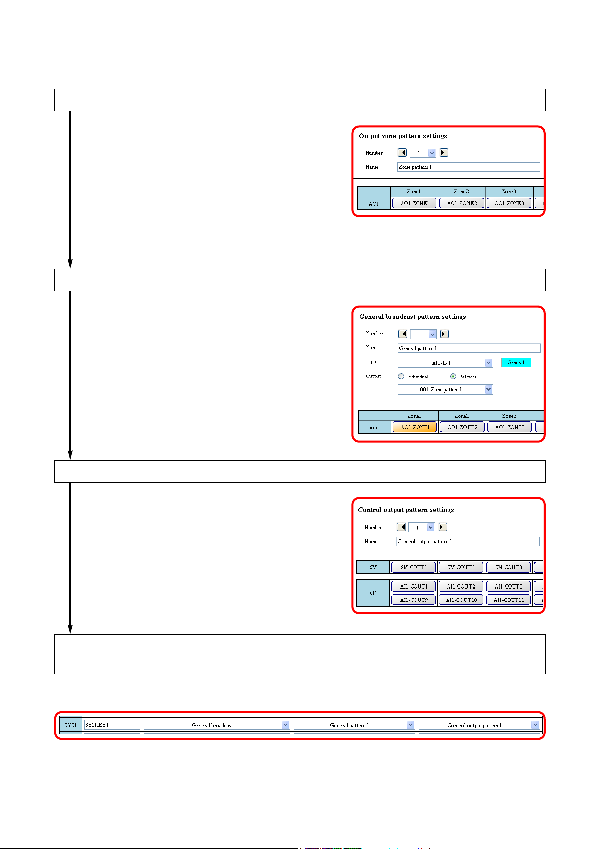
To make general-purpose pattern broadcasts, follow the procedures below to perform each setting using the
SX-2000 Setting Software.
Set the output zones to which general-purpose pattern broadcast is made.
When using the output zone pattern, set this in the
"Output zone pattern settings."
When setting the individual output zones, perform this setting in the "General broadcast pattern
settings."
Set the general-purpose broadcast patterns.
Perform this in the "General broadcast pattern
settings."
Set the control output to be interlocked with the control input or key operation. *
Perform this in the "Control output pattern settings."
* Perform this setting as needed.
Assign both the general-purpose broadcast pattern and control output pattern to
the control input or key of the device, or the key on the remote microphone.
Perform this in the "Event settings."
Page 7
7
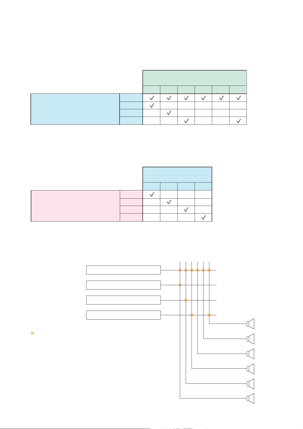
[General-purpose broadcast Pattern Setting Example]
In the example below, the table shows a pattern comprised of several general-purpose broadcast sound
sources and broadcast zones.
An output zone pattern is the one into which multiple broadcast zones are grouped, so broadcast can be
made to multiple zones simultaneously by activating only one pattern.
The input channels of the SX-2100AI (Audio Input Unit) are designated as sound sources for general-purpose
broadcasts or BGM, while the output channels (individual) or output zone patterns of the SX-2000AO (Audio
Output Unit) are designated as zones.
Broadcasts are made as follows when the above general-purpose broadcast pattern is used.
• Output zone pattern setting
Zones
SX-2000AO's output channels
123456
1
Output zone pattern (No.)
2
3
4
• General-purpose broadcast pattern setting
Zones
Output Zone Pattern
1234
CH1
Input Sources
SX-2100AI’s Input Channels (CH)
CH2
CH3
CH4
Output channel
123 546
Output zone pattern
SX-2100AI's CH1 sound source
SX-2100AI's CH2 sound source
SX-2100AI's CH3 sound source
SX-2100AI's CH4 sound source
shows the connection status between input (sound source) and
output channel (zone).
When multiple output zone patterns are activated simultaneously,
the broadcast is made based on the output zone pattern to which
the sound source with higher priority level is assigned.
1
2
3
4
Zone 1
Zone 2
Zone 3
Zone 4
Zone 5
Zone 6
Page 8
8
2.4. BGM Broadcasts
These broadcasts are generated by inputting audio signals originating only from BGM player devices into the
SX-2000 system, and are usually sent at relatively low volumes. BGM broadcasting is conducted by first
setting BGM patterns (comprised of various combinations of input channels, broadcast zones, etc.), then
activating these patterns. It is possible to perform settings so that multiple BGM sources are output to multiple
zones using a single BGM pattern. BGM patterns can be activated using the function keys on the front panel
of the SX-2000AI, SX-2100AI, SX-2000AO, or SX-2100AO, the keys on the RM-200SF, RM-200S, RM200SA, or RM-210, or the control input (pulse input) on the SX-2000SM, SX-2100AI, SX-2000AO, SX2100AO, or SX-2000CI.
To make BGM pattern broadcast, perform each setting using the SX-2000 Setting Software. The setting
procedures are the same as those of general-purpose pattern broadcast. However, there is no need to
perform output zone patterns.
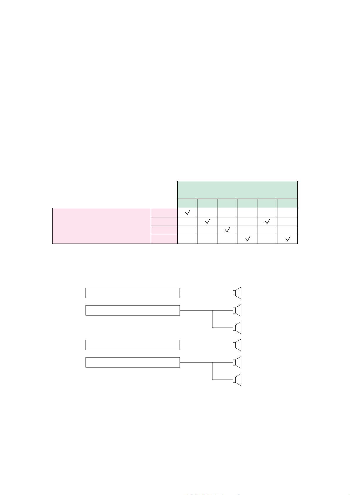
[BGM Pattern Setting Example]
In the example below, the table shows a pattern comprised of several BGM sound sources and broadcast
zones. The input channels of the SX-2100AI (Audio Input Unit) are designated as BGM input sources, while
the output channels of the SX-2000AO (Audio Output Unit) are designated as the zones.
Broadcasts are made as follows if the pattern shown in the table is used:
Zones
SX-2000AO’s Output Channels
123456
Input Sources
SX-2100AI’s Input Channels (CH)
CH1
CH2
CH3
CH4
Zone 1SX-2100AI’s CH1 sound source
Zone 2SX-2100AI’s CH2 sound source
Zone 5
Zone 3SX-2100AI’s CH3 sound source
Zone 4SX-2100AI’s CH4 sound source
Zone 6
Page 9
9
2.5. Emergency Broadcast
Emergency broadcast is conducted by first setting the combinations of the Emergency Sequences, Output
zones (individual or pattern), and Control Output patterns as Emergency Broadcast Patterns, then activating
these patterns by pressing the key on the remote microphone or via the control input of the system equipment.
A maximum of 128 patterns can be set for the Emergency Broadcast Patterns.
A combination of the EV message (sound source) and its broadcast duration is set as a single phase for the
Emergency Sequences, each of which can contain up to 3 levels of phases. A maximum of 4 Emergency
Sequences can be set.
Note
An EV message is a short form of Electronic Voice Message. These messages are
recorded as audio files.
The separately created EV messages are registered using the Setting Software, and
each message is set to one of 3 types: Alert, Evacuation, and Reset depending on the
contents.
The Alert and Evacuation messages are used in emergency situation, while the Reset
message is used to notify that the emergency situation is over.
Sixteen kinds of EV messages can be recorded on the SX-2000SM's CF card.
Output zone pattern is the one into which multiple
broadcast zones are grouped, so broadcast can be
made to multiple zones simultaneously by activating only
one pattern.
Similarly, control output pattern is the one into which
multiple control outputs are grouped. This control output
pattern can be used, for example, to activate multiple
control outputs in synchronization with the emergency
broadcast.
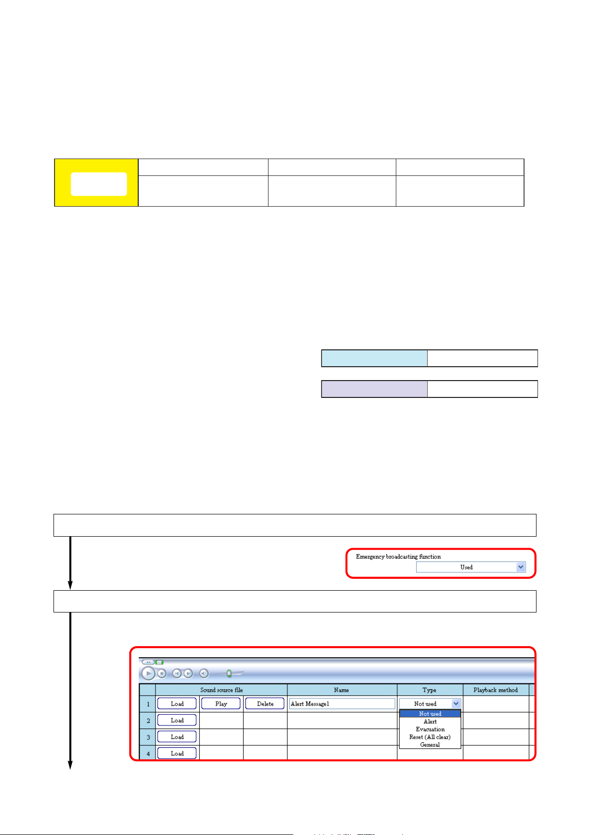
To use the emergency broadcasting function, follow the procedures below to perform each setting using the
SX-2000 Setting Software.
Set the emergency broadcasting function to "Used."
Perform this in the "Basic settings."
Register the EV messages.
Perform this in the "System settings (System manager)."
To the next page
Phase 1
Emergency
Sequence
EV message +
broadcast duration
Phase 2 Phase 3
EV message +
broadcast duration
Output zone pattern Multiple zones
Control output pattern Multiple control outputs
EV message +
broadcast duration
Page 10
10
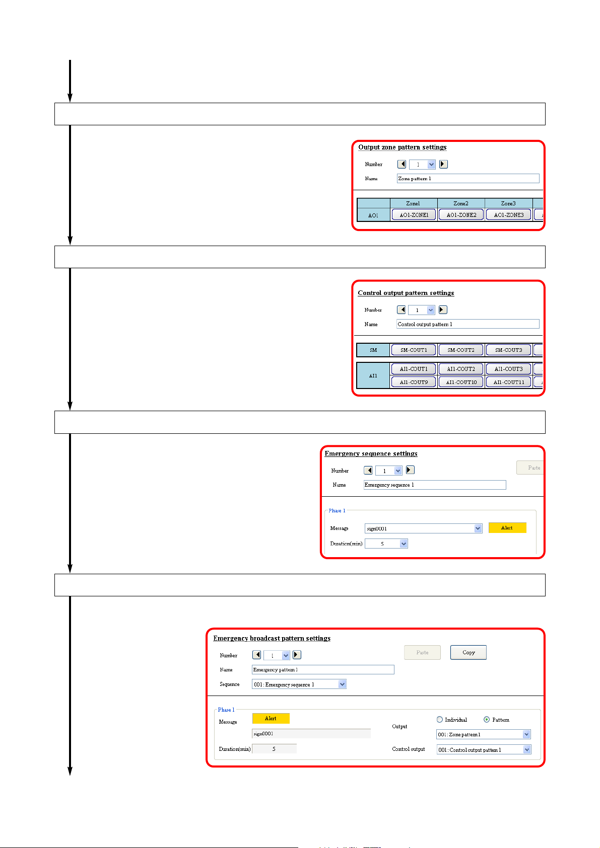
Set the output zones to make emergency broadcast.
Perform this in the "Output zone pattern settings."
Set the control output to be activated at the time of emergency broadcast*.
Perform this in the "Control output pattern settings."
* Perform this setting as needed.
From the previous page
Set the Emergency Sequences.
Perform this in the "Emergency sequence
settings."
Set the Emergency Broadcast Patterns.
Perform this in the "Emergency broadcast pattern settings."
To the next page
Page 11
11
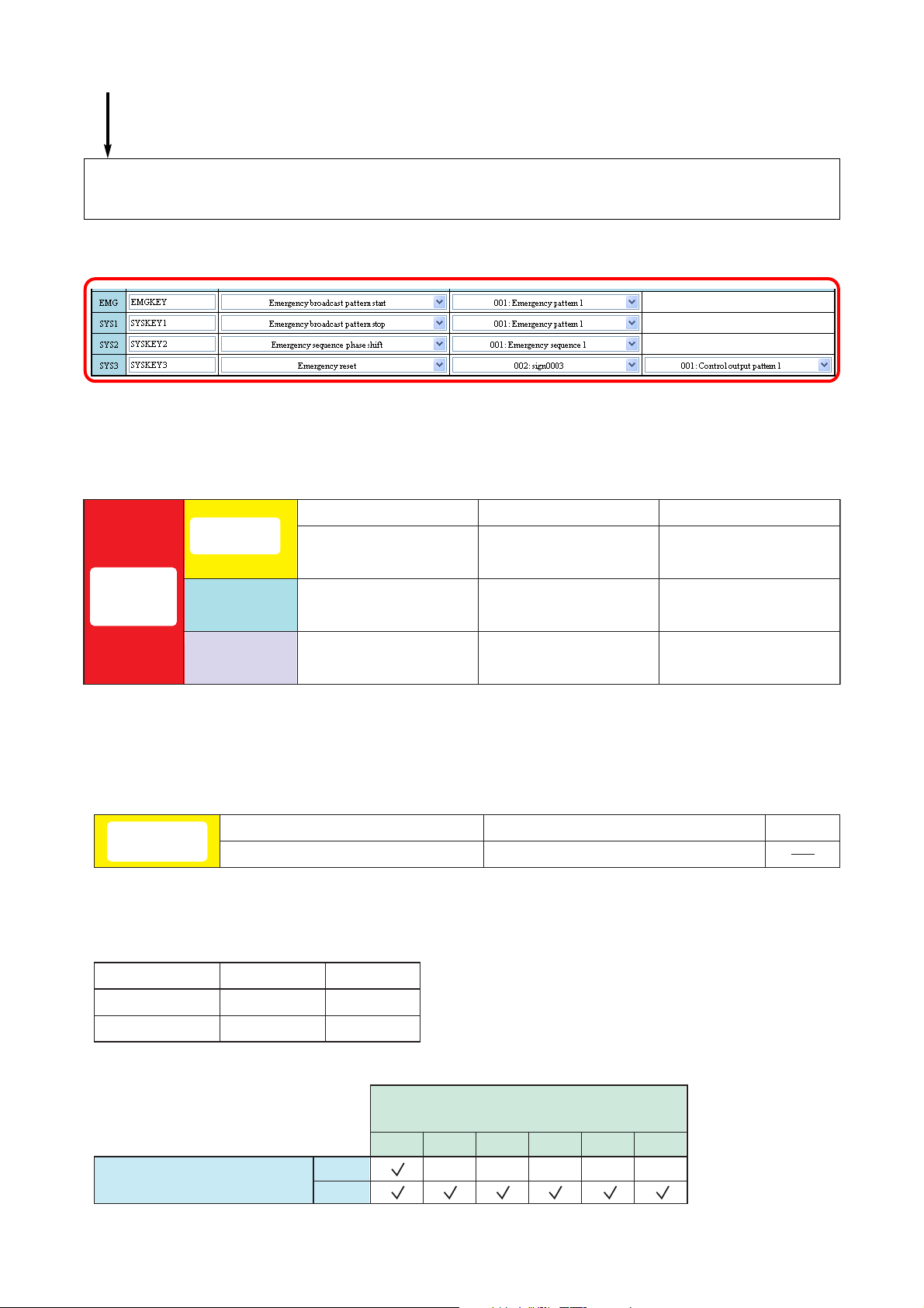
[Emergency broadcast setting example]
Assign each function to be used at the time of emergency broadcast to the
control inputs of the devices or the key on the remote microphone.
Perform this in the "Event settings."
From the previous page
[Emergency broadcast pattern configuration]
Phase 1
EV message +
broadcast duration
Emergency
broadcast
pattern
Emergency
sequence
Output zone
Control output
pattern
Individual or
pattern (multiple zones)
Multiple control outputs Multiple control outputs Multiple control outputs
• Emergency sequence settings
Emergency
sequence 1
Phase 3 is not set in this example.
Note:
• EV message settings
EV message 1, 5-minute broadcast
Phase 1
Phase 2
EV message +
broadcast duration
Individual or
pattern (multiple zones)
Phase 2 Phase 3
EV message 2, Continuous broadcast
Individual or
pattern (multiple zones)
Phase 3
EV message +
broadcast duration
Message name
EV message 1
EV message 2
• Output zone pattern setting
Output zone pattern (No.)
Audio file
sign001.wav
sign002.wav
Type
Alert
Evacuation
Zones
SX-2100AO's output channels
123456
1
2
Page 12
12
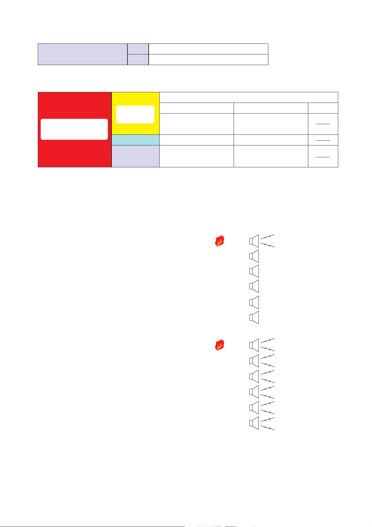
[Operation example]
The example here assumes that a fire breaks out in Zone 1.
(1) When the fire alarm sensor installed in Zone 1 works, the
automatic fire alarm system transmits a control signal to
the SX-2000 system's control input.
Then, the Emergency Broadcast Pattern 1 is activated,
allowing the alert message to be broadcast to Zone 1.
In this event, SX-2000SM's Control outputs 1 and 2 turn
ON.
(Phase 1)
(2) After 5 minutes, Phase 1 is shifted to Phase 2 and the
"Evacuation" EV message is broadcast to all zones.
In this event, SX-2000SM's Control outputs 1 and 2 turn
OFF, while SX-2100AI's Control outputs 1 and 2 turn
ON.
• Control output pattern settings
Control output pattern (No.)
1
2
• Emergency broadcast pattern settings
SX-2000SM's control outputs 1 and 2
SX-2100AI's control outputs 1 and 2
Emergency sequence 1
Phase 1
Emergency broadcast
Emergency
sequence
EV message 1,
5-minute broadcast
pattern 1
Output zone
Control output
pattern
Output zone pattern 1 Output zone pattern 2
Control output pattern 1 Control output pattern 2
Phase 2
EV message 2,
Continuous broadcast
Zone 1
Zone 2
Zone 3
Zone 4
Phase 3
Alert message is
being broadcast.
Zone 5
Zone 6
Zone 1
Zone 2
Zone 3
Zone 4
Zone 5
Zone 6
Evacuation message
is being broadcast.
Evacuation message
is being broadcast.
Evacuation message
is being broadcast.
Evacuation message
is being broadcast.
Evacuation message
is being broadcast.
Evacuation message
is being broadcast.
Page 13
13
2.6. Surveillance Function
Surveillance function continuously monitors such status at the major points from input to output of the system
as each unit operation, cable connections or communications between the units, and power supply.
If a unit fails or cable breaks, this is notified to the system operator by some means. Failure status of the
external equipment can also be accepted and notified.
When a failure has occurred, perform a set of operations: failure reception first to acknowledge failure state
and finally failure reset to restore the system to normal using the keys on the SX-2000SM or remote
microphone, or control input terminals of the system equipment.
Set the Surveillance intervals, intended surveillance points, and actions at the time of failure occurrence using
the SX-2000 Setting Software.
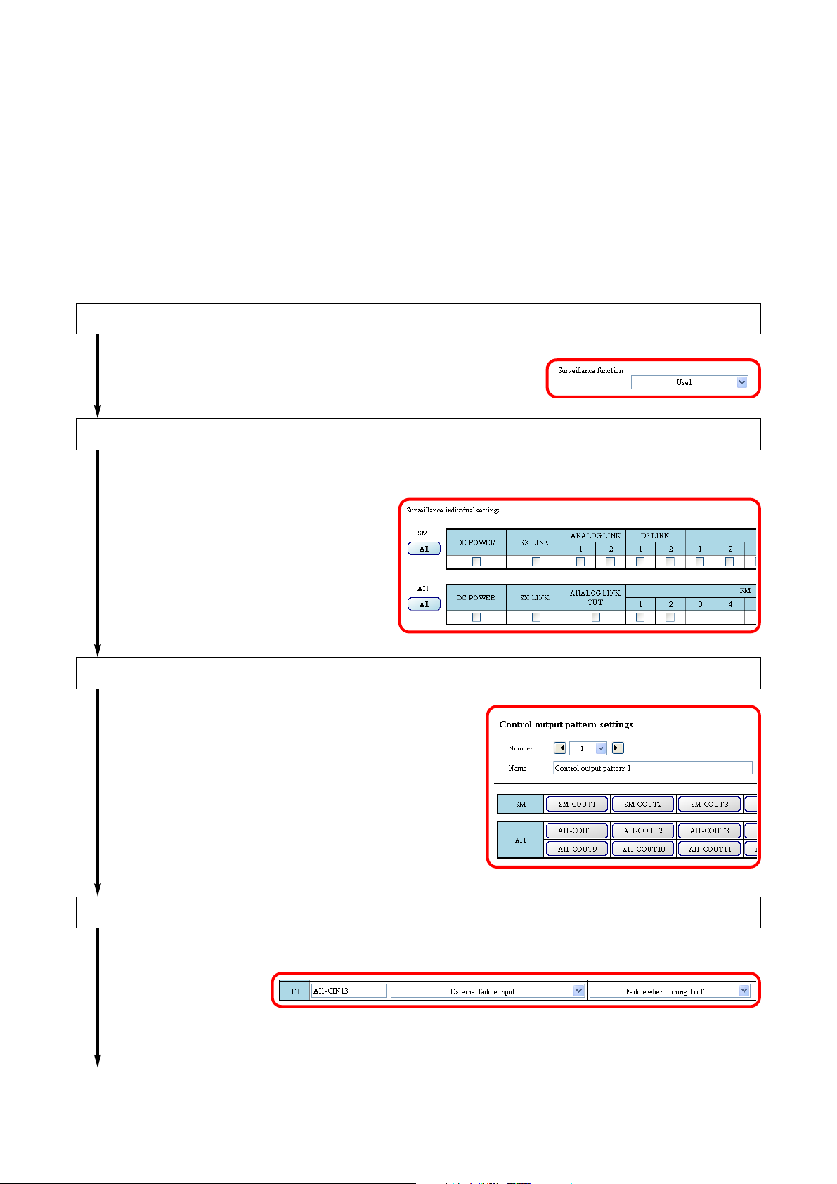
To use the Surveillance function, follow the procedures below to perform each setting.
Set the Surveillance function to "Used."
Perform this in the "Basic settings."
Set the surveillance points of each device.
Perform this in the "Surveillance individual settings."
Set the control outputs to be activated at the time of failure detection. *
Perform this in the "Control output pattern settings."
* Perform this setting as needed.
Assign the "External failure input" function to the control input*.
Perform this in the "Event settings."
* Perform these settings as needed.To the next page
Page 14
14
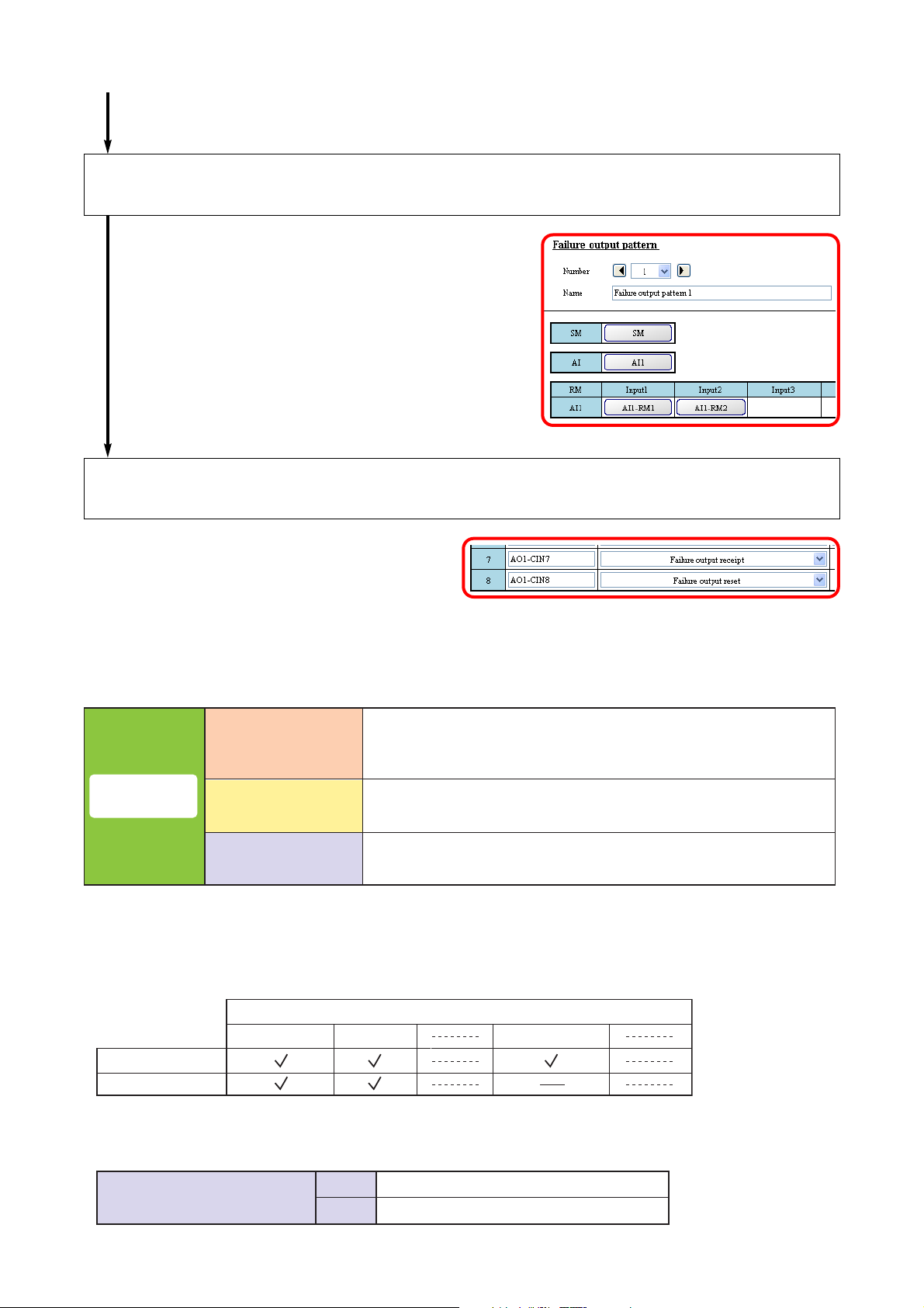
Select the surveillance target devices or the surveillance points in the SX-2000
system.
Perform this in the "Failure output pattern settings."
Assign the Failure acknowledgement and Failure Status Reset functions to the
control inputs of the device or the keys on the remote microphone.
Perform this in the "Event settings."
From the previous page
[Failure output pattern configuration]
[Example of assigning the Surveillance function to the remote microphone]
Each device, each surveillance point (Set the surveillance points
Failure output
pattern
Surveillance target
External failure input
Failure state output
of each device in the SX-2000 system in the Surveillance settings
individually.)
Control input terminal
(Control input set to "External failure input" in the Event settings.)
Control output pattern
(Multiple control outputs)
• Surveillance individual settings
SX-2000SM
SX-2100AI (1)
• Control output pattern settings
Control output pattern (No.)
Surveillance point
Control input 1Power supply SX link
3
SX-2000SM's control outputs 3 and 4
4
SX-2100AI's control outputs 3 and 4
Page 15

15
• Remote microphone's function key settings
Key Function Contents
Function key 3
Failure output receipt
Failure output receipt
Failure output reset
Failure output
pattern 1
Failure output
pattern 2
Surveillance target
External failure inputFunction key 1
Failure status output
Surveillance target
External failure inputFunction key 2
Failure status output
SX-2000SM
None
Control output pattern 3
SX link
None
Control output pattern 4
Page 16

16
3. NOTES ON PERFORMING SETTINGS
3.1. System Requirements
• OS: Windows Vista, Windows XP SP2 or later
• CPU: 800 MHz or faster
• Memory: 512 MB or more
• Application software: Microsoft Excel*1, Windows Media Player 9.0 or later*
2
• Environment to support CF card*
3
*1Needed to print labels using the SX-2000 Setting Software. Use the Microsoft Excel 2007 or later for the
Windows Vista or Microsoft Excel 2000 or later for the Windows XP SP2.
*
2
Needed to preview the EV messages using the SX-2000 Setting Software.
*
3
Combination of a PC card slot and CF card adapter (supplied), or an external CF card/writer device is needed.
Note
Windows, Windows Vista, Microsoft Excel, and Windows Media are trademarks of Microsoft Corporation.
3.2. Notes
3.2.1. Compact flash cards
[Data storage]
When storing settings data created using the SX-2000 Setting Software on a CF card, use the included card.
On the CF card, do not store any files other than those related to the software. Failure to do so may cause the
unit malfunction.
[Card Removal & Insertion]
Do not remove nor insert the CF card while settings data is being written or read, as doing so may cause data
loss or damage the card.
[Prohibition]
Never use any CF card that has been used for other devices.
3.2.2. Displays
The SX-2000 Setting Software creates window displays at a resolution of 1024 x 768 pixels. Setting the
screen size to a lower resolution or resizing windows may cause a portion of display to be hidden or cut off.
3.2.3. Window screens
The windows displayed by the SX-2000 Setting Software in this manual are examples and may vary
somewhat depending on the specific environment of the PC used.
Page 17
17
3.3. Setting Procedures
3.3.1. Offline operation
3.3.2. Online operation
The following procedure is recommended when performing settings online.
1. Perform all settings using the SX-2000 software.
2. Output setting data file and save it to a CF card.
(Refer to p. 167 "Saving the Settings File.")
3. Insert the CF card into the SX-2000SM to read the setting data.
(Refer to the separate Installation Manual, "Inserting a CF card.")
1. Connect all SX-2000 system components.
(Insert the CF card into the SX-2000SM in advance.)
(For details, refer to the separate Installation Manual.)
2. Use a cable to connect the SX-2000SM to a PC installed
with the SX-2000 software.
(Refer to p. 155, Step 1 of "Establishing Communications Between the SX-2000SM and a PC.")
3. Set up the SX-2000SM network with the SX-2000 software.
(Refer to p. 29 "(3) Network Settings" of "Basic Settings,"
p. 31 "Detecting the SX-2000SM's Network Settings,"
p. 38 "Changing the SX-2000SM's Network Settings."
5. Acquire the system configuration data through configuration reception.
(Refer to p. 161, "Acquiring System Configuration Data Online.")
6. Perform settings other than system configuration.
7. Write the setting data from PC to the CF card online.
(Refer to p. 159, "Writing Setting Data to the CF Card Online.")
4. Connect and establish communications between the SX-2000SM and the PC.
(Refer to p. 155, Step 2 of "Establishing Communications Between the SX-2000SM and a PC.")
Page 18
18
4. SOFTWARE SETUP
Notes
• Close all open applications before installing.
• To install the software, it is necessary to log in to the PC using an administrator account.
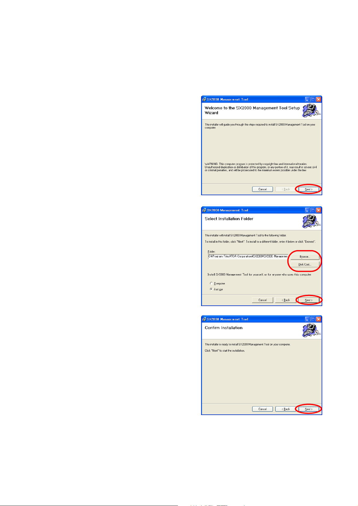
4.1. Setting Software Installation
Step 1. Click on "setup.exe" in the setting software folder
contained in the CD supplied with the SX-2000SM.
The installation wizard screen is displayed.
Note
The installation wizard screen may not be displayed.
In this case, read the next page.
Step 2. Click the [Next] button.
The Select Installation Folder screen is displayed.
Step 3. Change the folder as needed, then click the [Next]
button.
The Confirm Installation dialog is displayed.
Step 4. Click the [Next] button to start installing the software.
Page 19
19
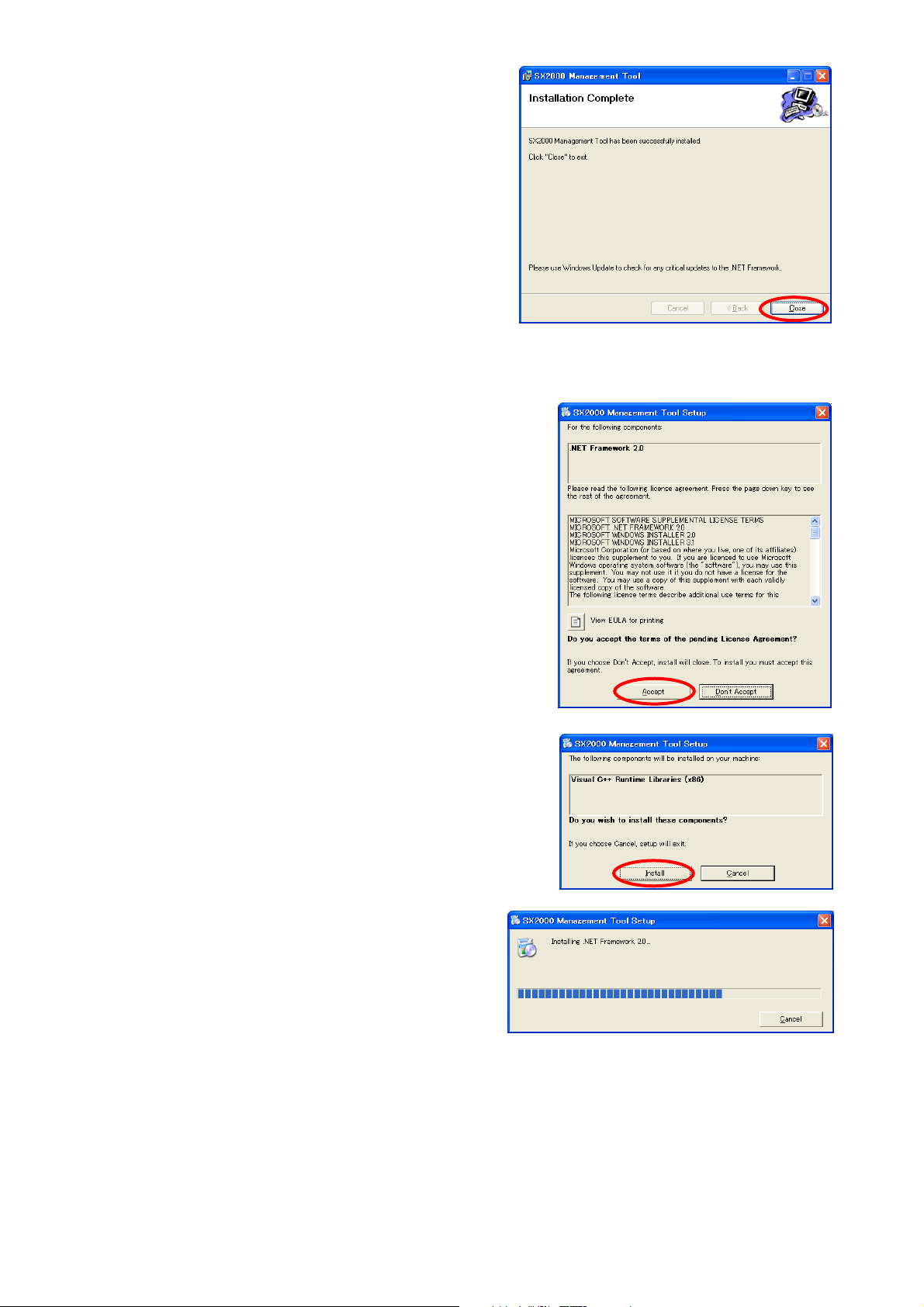
Step 5. When the Installation Complete dialog is displayed,
click the [Close] button to complete the installation.
[If no installation wizard screen is displayed]
The screen at right may be displayed when the Step 1 is
performed. In this case, install the software needed to run
the SX-2000 Setting Software with the steps below.
Step 1. Click the [Accept] button.
The software installation screen is displayed.
Step 2. Click the [Install] button.
Installation in progress screen is displayed.
As the installation wizard screen is displayed after completion of installation, follow the steps shown on the
previous page.
Page 20
20
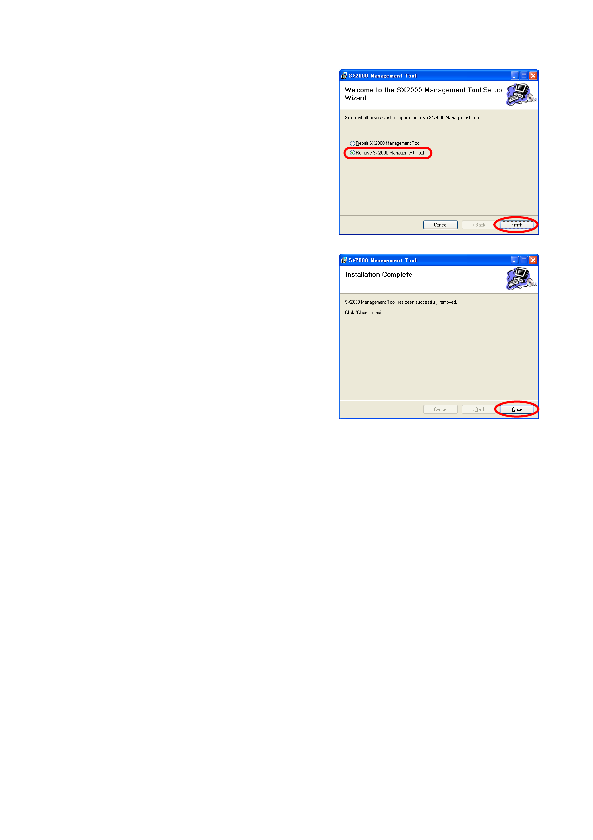
4.2. Uninstallation
Step 1. Click on "setup.exe" in the setting software folder
contained in the CD supplied with the SX-2000SM.
The setup wizard screen is displayed.
Step 2. Select "Remove SX2000 Management Tool," and
click the [Finish] button to start uninstalling the
software.
Step 3. When the Installation Complete dialog is displayed,
click the [Close] button to complete the uninstallation.
Page 21
21
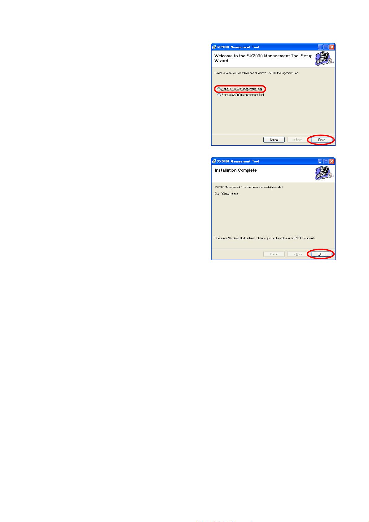
4.3. Update
Step 1. Click on "setup.exe" in the setting software folder
contained in the CD supplied with the SX-2000SM.
The setup wizard screen is displayed.
Step 2. Select "Repair SX2000 Management Tool," and click
the [Finish] button to start updating the software.
Step 3. When the Installation Complete dialog is displayed,
click the [Close] button to complete the update.
Page 22
22
5. RUNNING THE SX-2000 SETTING SOFTWARE
5.1. Running The SX-2000 Setting Software
To start the software, select "TOA Matrix Series SX2000" from the Start menu, or double-click the
SX2000 shortcut icon on the desktop.
Start menu Shortcut icon on the desktop
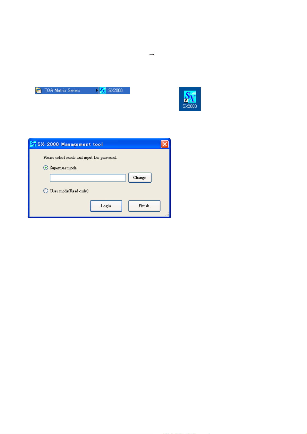
The login screen is displayed.
Two modes are made available for the SX-2000 Setting Software: Superuser mode and User mode, which are
different in login method.
In Superuser mode, the setting data can be newly created and the preset data can be edited.
This mode requires a login password, which can also be changed in this login screen.
In User mode, no setting data can be changed.
But, it is possible to perform operations requiring no setting data change such as setting content confirmation,
setting data's read and print, and label print for the remote microphone.
Page 23
23
5.2. Login In Superuser Mode
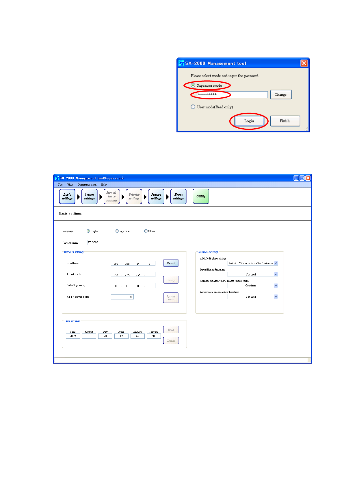
5.2.1. How to login
Step 1. Select "Superuser mode" in the login screen,
then enter the password.
Note
Password is "Superuser" by default.
Passwords are case-sensitive.
Step 2. Click the [Login] button.
The initial screen of the Setting Software is displayed.
1
2
Page 24
24
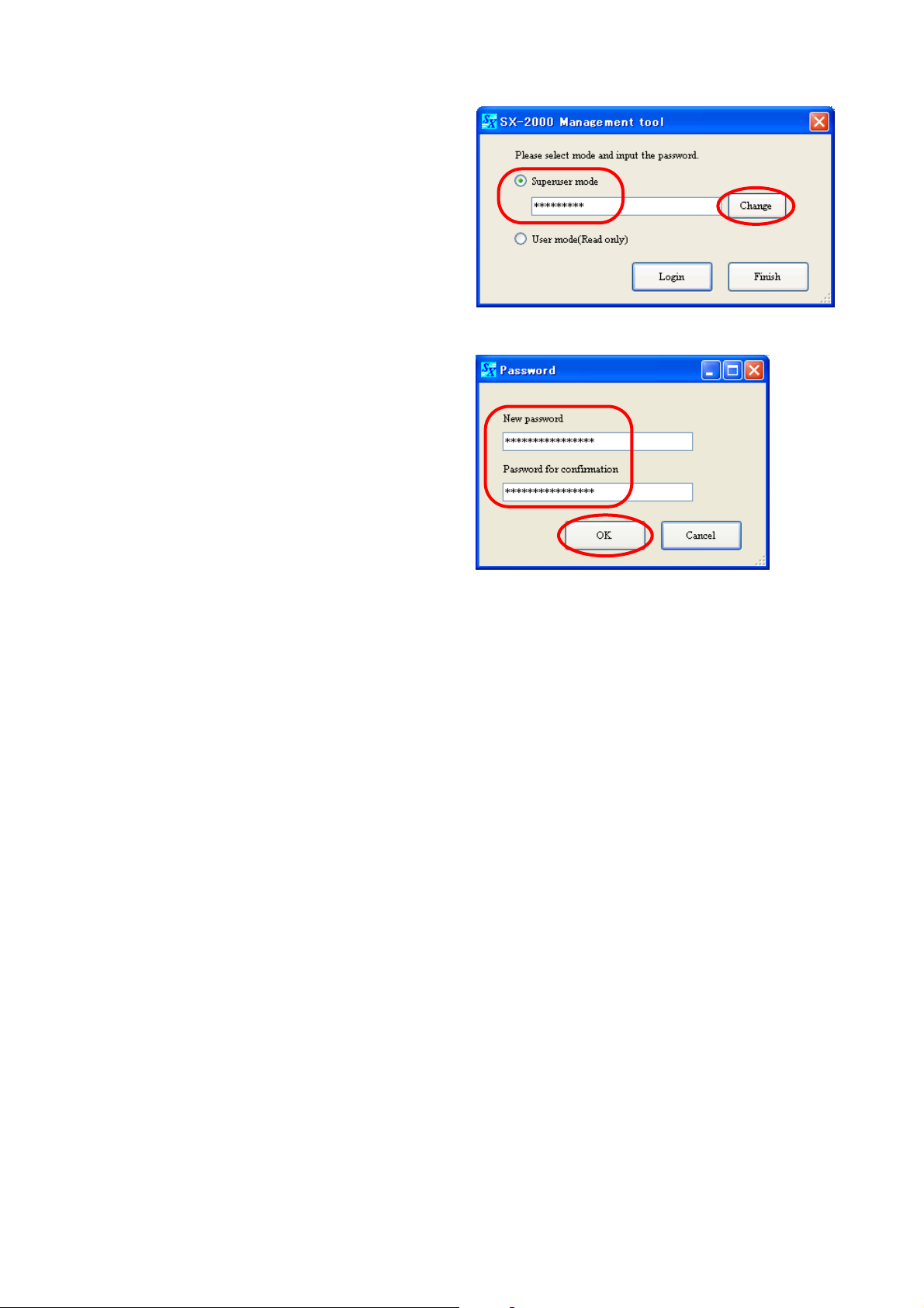
5.2.2. Password change
Step 1. Select "Superuser mode" in the login screen,
then enter the current password.
Note
Password is "Superuser" by default.
Passwords are case-sensitive.
Step 2. Click the [Change] button.
The password change screen is displayed.
Step 3. Enter the desired password in the New
password field, then reenter the same
desired password in the Password for
confirmation filed.
Note
Up to 16 alphanumeric characters can be
used.
Step 4. Click the [OK] button.
The display reverts to the login screen.
1
2
3
4
Page 25
25
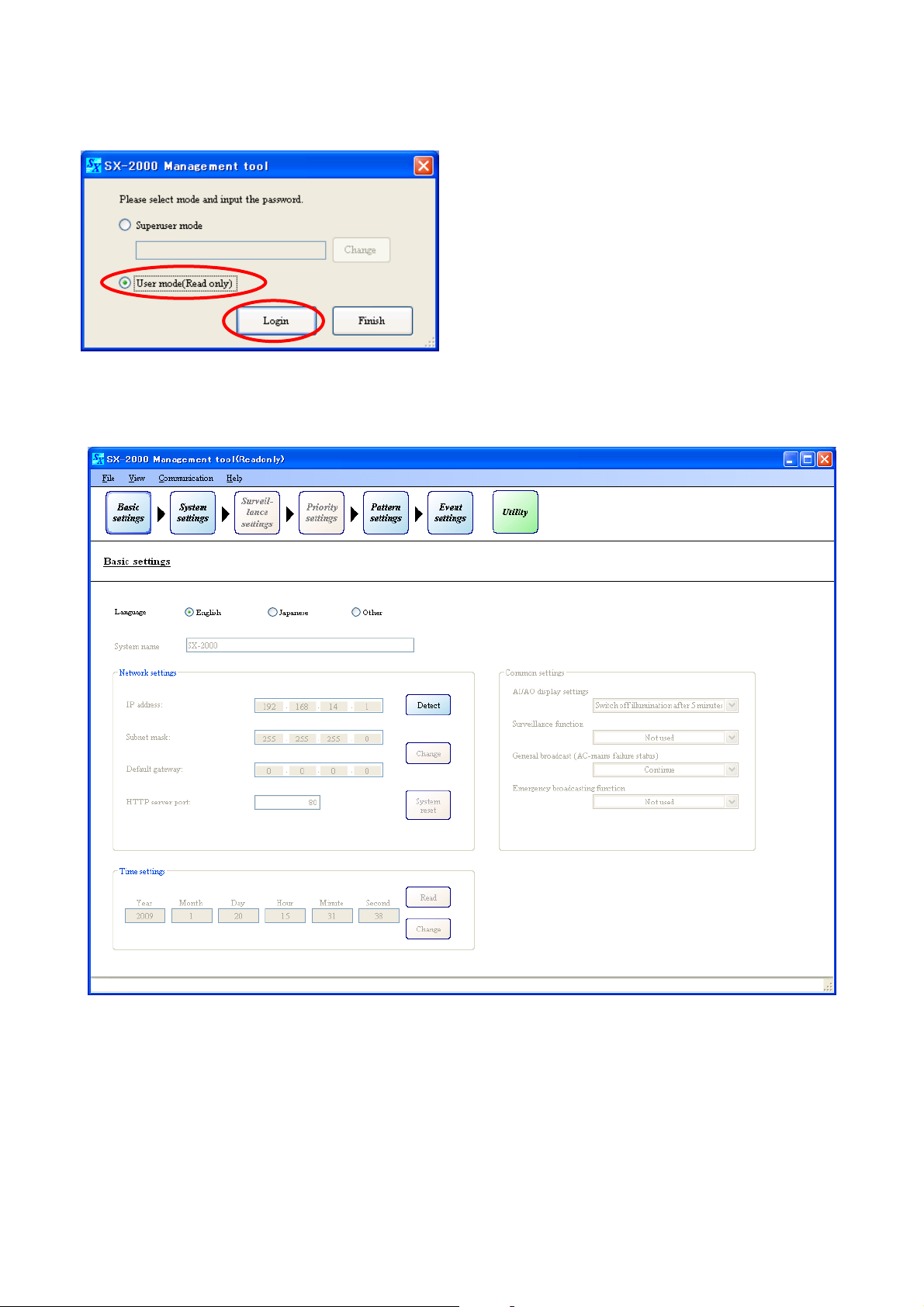
5.3. Login In User Mode
Select "User mode (Read only)" in the login screen, then click the [Login] button.
The initial screen of the Setting Software is displayed.
The data shaded in gray cannot be changed.
Note
When changing the mode from User to Superuser, first exit and restart it, then login again in Superuser mode.
Page 26
26
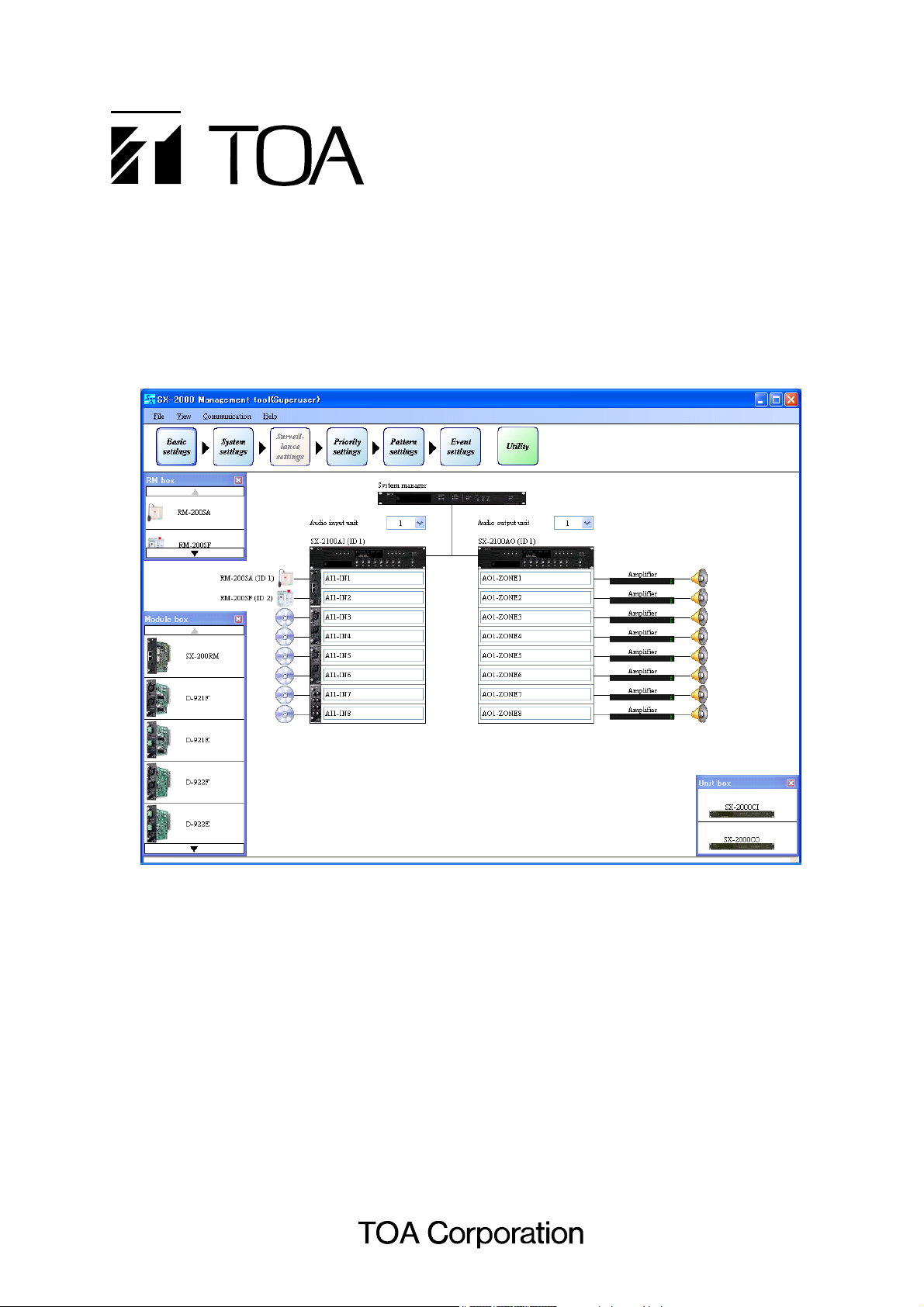
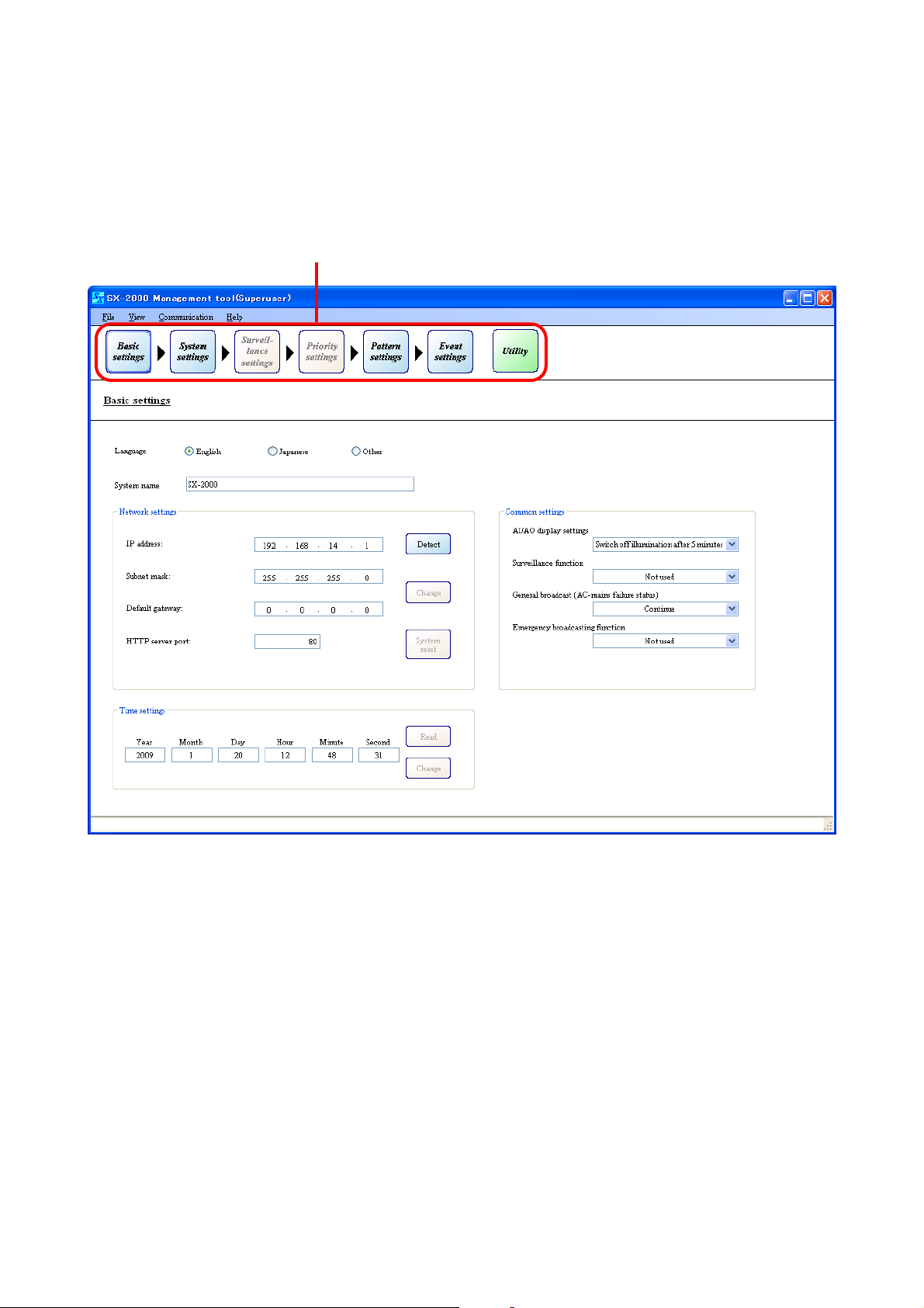
6. SETTING ITEMS AND PROCEDURES
Setting item buttons are located in the upper portion of the screen.
The entire system setting is divided into 6 steps of settings starting with "Basic settings" to "Event settings"
from left to right. Be sure to make settings in this order.
Clicking on each setting item button displays the corresponding setting screen in the main area below the
setting item buttons.
Setting items
Page 27
27
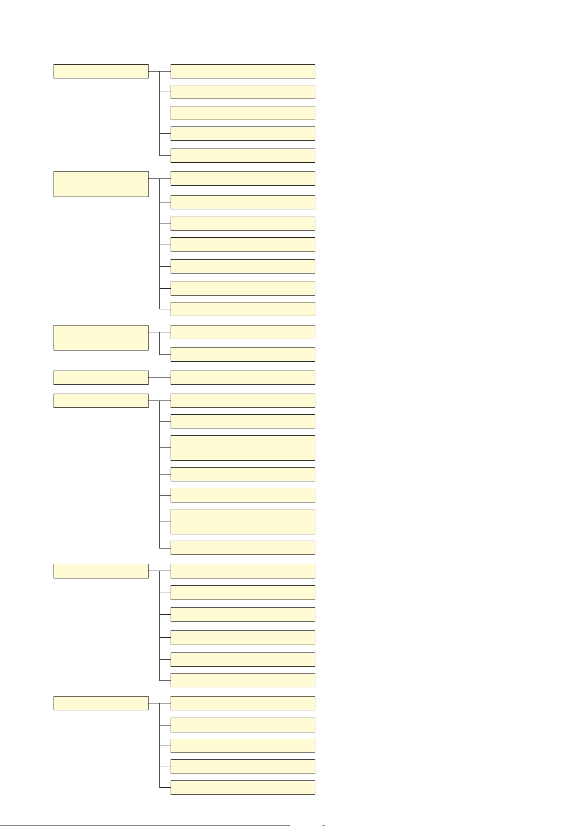
6.1. Menu Configuration
Basic settings
(p. 29)
System settings
(p. 44)
Surveillance settings
(p. 69)
Language setting
System name setting
Network settings
Common settings
Time settings
SX-2000SM
SX-2000AI, SX-2100AI
RM-200SF
RM-200S, RM-200SA
SX-2000AO, SX-2100AO
SX-2000CI
SX-2000CO
Interval settings
Surveillance individual settings
(p. 29)
(p. 29)
(p. 29)
(p. 30)
(p. 30)
(p. 45)
(p. 50)
(p. 55)
(p. 58)
(p. 61)
(p. 65)
(p. 67)
(p. 69)
(p. 70)
Select the displayed language.
Set the desired system name.
Make network-related settings.
Make settings related to the SX-2000AI/2100AI/2000AO/
2100AO, Surveillance function, and Emergency.
Set the current time for the SX-2000SM.
Set each name of the control inputs and outputs, and register
EV messages.
Configure the modules used for the SX-2000AI or SX-2100AI,
and set each name of the control inputs and outputs.
Make function settings and set the unit name.
Make function settings and set the unit name.
Configure the audio outputs, and set each name of the
control inputs and outputs.
Set each name of the control inputs.
Set each name of the control outputs.
Set the start time and interval time for confirming failure
status of the external devices.
Set each device's individual points to be detected for failure.
Priority settings
Pattern settings
Event settings
(p. 71)
(p. 74)
(p. 87)
Priority settings
Output zone pattern settings
BGM pattern settings
(p. 71)
(p. 77)
(p. 78)
General broadcast pattern
settings
Control output pattern settings
Emergency sequence settings
(p. 79)
(p. 81)
(p. 82)
Emergency broadcast pattern
settings
Failure output pattern settings
(p. 83)
(p. 85)
System event settings (p. 100)
SM event settings
AI event settings
AO event settings
RM event settings
(p. 101)
(p. 105)
(p. 109)
(p. 112)
Set the priority levels for General-purpose, Emergency, and
BGM broadcasts.
Set broadcast zones as Output zone pattern.
Set BGM broadcast zones as BGM pattern.
Set General-purpose broadcast zones as General broadcast
pattern.
Set the control outputs to use as Control output pattern.
Set the sequence of Emergency broadcast.
Register a set of Emergency sequence, output zone, and
control output pattern as Emergency broadcast pattern.
Set detection points for failure as Failure output pattern.
Set control output patterns invoked in Emergency broadcast
state or at power failure.
Assign functions to the control inputs.
Assign functions to the function keys, channel keys, and
control inputs.
Assign functions to the function keys, channel keys, and
control inputs.
Assign functions to the keys.
Utility
(p. 120)
CI event settings
(p. 119)
Log file display (p. 121)
Online log (p. 125)
System status
Audio input and output status
(p. 128)
(p. 147)
Control input and output status (p. 151)
Assign functions to the control inputs.
Displays the log data stored on the CF card, and exports the
log data.
Displays log data online.
Displays system configuration or failure status online.
Displays audio input and output status online.
Displays control input and output status online.
Page 28

28
6.2. Menu Bar
•File
New: Creates a new file of data set using the SX-2000 Setting Software.
O
pen: Reads the stored data of the SX-2000 Setting Software.
S
ave: Saves data of the SX-2000 Setting Software in edit.
Data output (P
):
Setting data (C): Exports the setting data in csv format.
RM label (L): Exports the data for creating the RM-200SF's, RM-200S's, RM-200SA's, and RM-
210's label in xls format.
E
xit: Exits the SX-2000 Setting Software.
•View
Basic settings: Moves to the Basic settings screen.
S
ystem settings: Moves to the System settings screen.
Surveillance settings (V
): Moves to the Surveillance settings screen.
P
riority settings: Moves to the Priority settings screen.
Pattern settings (A
): Moves to the Pattern settings screen.
E
vent settings: Moves to the Event settings screen.
U
tility: Moves to the Utility screen.
M
odule box: Displays or hides the Module box in the System settings screen.
R
M box: Displays or hides the RM box in the System settings screen.
U
nit box: Displays or hides the Unit box in the System settings screen.
•C
ommunication
C
onnect (F5): Initiates communications between the SX-2000SM and a PC.
(Refer to p. 155 "Establishing Communications Between the SX-
2000SM and a PC.")
D
isconnect (Shift + F5): Terminates communications between the SX-2000SM and the PC.
SX CF Online read [SX
-
> PC] (R
): Reads setting data from the CF card.
SX CF Online write [PC
-
> SX] (W): Writes setting data to the CF card.
Receive configuration (S
): Receives current system configuration information.
Receive all log files (L
): Acquires all log data contained in the CF card.
•Help
Version (A
): Displays the version number of the SX-2000 Setting Software.
Page 29
29
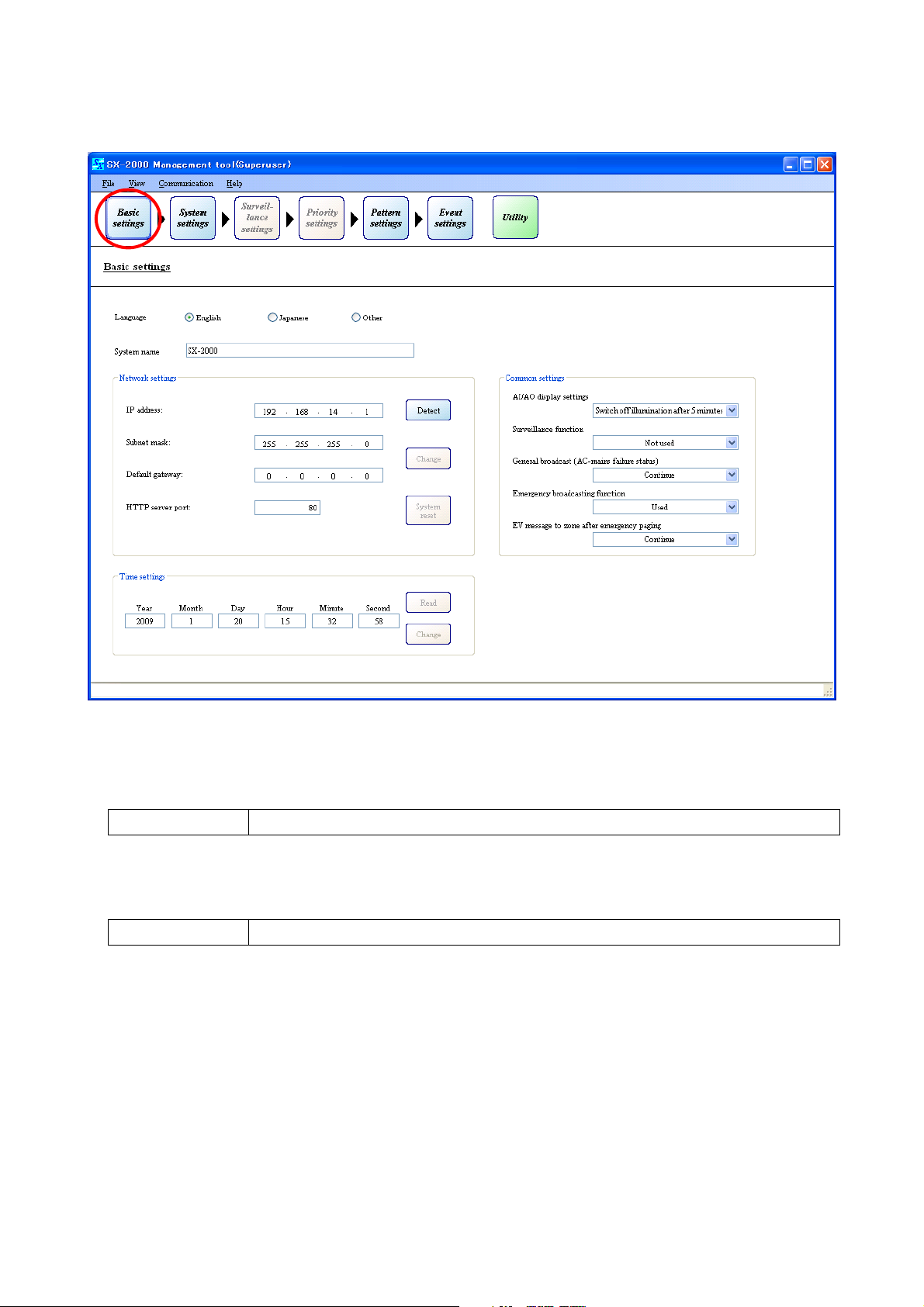
BASIC SETTINGS
7. BASIC SETTINGS
Pressing the [Basic settings] button displays the screen below.
(1) Language Setting
Select the language to use.
Note: "Other" is not used.
English (default), Japanese, Other
Available Settings
(2) System Name Setting
Enter the system name.
(3) Network Settings
Set the IP address, subnet mask, default gateway, and HTTP server port.
The network settings are used for online connection. Perform settings according to the network
environment of the PC to be connected.
Consult the network administrator for details.
[Default settings]
· IP address: 192.168.14.1
· Subnet mask: 255.255.255.0
· Default gateway: 0.0.0.0
· HTTP server port: 80
Connecting the SX-2000SM to a PC makes it possible to acquire and modify the SX-2000SM's network
settings. (Refer to p. 31 "Detecting the SX-2000SM's Network Settings," p. 38 "Changing the SX-2000SM's
Network Settings.")
Up to 32 alphanumeric characters. (default: SX-2000)
Available Settings
(1)
(2)
(3)
(5)
(4)
Page 30
30
BASIC SETTINGS
(4) Common Settings
• AI/AO display settings
Select the extinguish time for the vacuum fluorescent displays (VFD) on the SX-2000AI, SX-2100AI, SX2000AO, and SX-2100AO.
Switch off illumination after 5 minutes (default), Always illumination
Available Settings
• Surveillance function setting
Set whether or not to use this function in each individual part of the SX-2000SM, SX-2000AI, SX-2100AI,
SX-2000AO, SX-2100AO, SX-2000CI, SX-2000CO, RM-200SF, and RM-200SA.
Not used (default), Used
Available Settings
• Emergency broadcasting function
Set whether or not to use the Emergency Broadcasting function.
Not used (default), Used
Available Settings
• General broadcast (AC-mains failure status)
Set whether or not general broadcasts will be continued when a power failure occurs.
Continue (default), Stop
Available Settings
• EV message to zone after emergency paging
Set whether to enable or disable EV Message (broadcast of the message registered as sound source of
the emergency broadcast) to the zones after the Emergency RM broadcast by microphone
announcement is completed.
Continue (default), Stop
Available Settings
Note: This function is available only when the "Emergency" broadcast function is set to "Used."
(5) Time Settings
Set the year, month, day, hour, minute, and second. (Refer to p. 42)
When "Switch off illumination after 5 minutes" is selected for the VFD’s extinguish time, the screen
automatically goes out if no operation is performed for 5 minutes. Pressing any keys other than the
function keys on the front panel resets the screen display.
Note
The VFD is an expendable item.
Its display quality deteriorates with age.
As operation in "Always illumination" mode will accelerate aging, normally set to "Switch off illumination
after 5 minutes."
Page 31

31
7.1. Detecting the SX-2000SM's Network Settings
It is possible to acquire the SX-2000SM's network settings by connecting the SX-2000SM to a PC.
7.1.1. When a single SX-2000SM is connected to the switching hub
Step 1. Connect the SX-2000SM and the PC installed with the SX-2000 software to the switching hub.
Connect the SX-2000SM's LAN connection terminal to a 10BASE-T- or 100BASE-TX-compatible
switching hub.
Use STP Category 5 Standard straight LAN cable fitted with RJ45 connectors.
Notes
• Do not connect the switching hub to the LAN.
• Avoid directly connecting the SX-2000SM to the PC via a cross cable.
Step 2. Click the [Detect] button.
BASIC SETTINGS
Detecting the SX-2000SM's Network Settings
Switching hub
Straight cable
SX-2000SM
LAN connection terminal
Straight cable
PC installed with the SX-2000
software
Page 32

Communications begin.
The following screen is displayed during communications.
The detected SX-2000SM's network settings are displayed after communication is completed.
Pressing the [Cancel] button during communications displays the following screen.
32
BASIC SETTINGS
Detecting the SX-2000SM's Network Settings
Page 33

7.1.2. When the PC is set for multiple networks
Step 1. Connect the SX-2000SM and the PC installed with the SX-2000 software to the switching hub.
Connect the SX-2000SM's LAN connection terminal to a 10BASE-T- or 100BASE-TX-compatible
switching hub.
Use STP Category 5 Standard straight LAN cable fitted with RJ45 connectors.
Notes
• Do not connect the switching hub to the LAN.
• Avoid directly connecting the SX-2000SM to the PC via a cross cable.
Step 2. Click the [Detect] button.
33
BASIC SETTINGS
Detecting the SX-2000SM's Network Settings
Switching hub
Straight cable
SX-2000SM
LAN connection terminal
Straight cable
PC installed with the SX-2000
software
Page 34

Communications begin.
The following screen is displayed during communications.
The screen for IP address selection is displayed after communication is completed.
Pressing the [Cancel] button during communications displays the following screen.
Step 3. Select the IP address to be used, then press the [OK] button.
The detected SX-2000SM's network settings are displayed.
34
BASIC SETTINGS
Detecting the SX-2000SM's Network Settings
Page 35

7.1.3. When multiple SX-2000SMs are connected to a switching hub
Step 1. Connect the SX-2000SM and the PC installed with the SX-2000 software to the switching hub.
Connect the SX-2000SM's LAN connection terminal to a 10BASE-T- or 100BASE-TX-compatible
switching hub.
Use STP Category 5 Standard straight LAN cable fitted with RJ45 connectors.
Notes
• Do not connect the switching hub to the LAN.
• Avoid directly connecting the SX-2000SM to the PC via a cross cable.
35
BASIC SETTINGS
Detecting the SX-2000SM's Network Settings
Step 2. Click the [Detect] button.
Switching hub
Straight cable
SX-2000SM
MAC address for the LAN
LAN connection
terminal
Straight cable
PC installed with the SX-2000
software
Page 36

Communications begin. The following screen is displayed during communications.
The screen for MAC address selection is displayed after communication is completed.
Pressing the [Cancel] button during communications displays the following screen.
Step 3. Select the MAC address of the SX-2000SM to be detected, then press the [OK] button.
Refer to the MAC address for the LAN shown on the SX-2000SM's rear panel.
The detected SX-2000SM's network settings are displayed.
36
BASIC SETTINGS
Detecting the SX-2000SM's Network Settings
Note
If the same IP address is duplicated among the SX-2000SMs connected to the switching hub, correct
communications may not be established between the SX-2000SM and the PC
(p. 155).
Be sure to confirm the IP addresses of all connected SX-2000SMs. If an address is found to be
duplicated, change the network settings following Step 3. (Refer to p. 38 "Changing the SX-2000SM's
Network Settings.")
Make communication connections only after assuring that different IP addresses are set for all SX2000SMs.
Page 37

7.1.4. When no SX-2000SM's network settings are detected
When the SX-2000SM's network settings were not detected, the following screen is displayed.
If this display appears, the following causes can be considered.
Connection of LAN cable LAN cables not connected.
Not straight cable but cross cable is connected.
STP Category 5 Standard straight cable with RJ45 connectors is
not used.
Power of HUB Switching hub is not powered.
The distance between the SX-2000SM and the switching hub is
more than 100 m.
DC power of SX-2000SM Power is not supplied to the SX-2000SM.
Connection port of SX-2000SM Cable is not connected to the SX-2000SM's LAN connector.
Firmware version of SX-2000SM The SX-2000SM firmware is earlier than Version 3.00.
Since its latest version is made available on the TOA product
download site (http://toa-products.com/), please download it
for use.
Network settings The IP address, subnet mask, default gateway or HTTP server port of
the SX-2000SM or PC is not correctly set.
37
BASIC SETTINGS
Detecting the SX-2000SM's Network Settings
Page 38

7.2. Changing the SX-2000SM's Network Settings
The IP address, subnet mask, default gateway and HTTP server port settings can be changed after detecting
the SX-2000SM's network settings.
Step 1. Change the network setting values after detecting the SX-2000SM's network settings.
Note
For network setting detection, refer to p. 31 "Detecting the SX-2000SM's Network Settings."
The [Change] button can be used after the values have been changed.
Step 2. Click the [Change] button.
38
BASIC SETTINGS
Changing the SX-2000SM's Network Settings
Page 39

Changes in network settings are reflected in the SX-2000SM.
39
BASIC SETTINGS
Changing the SX-2000SM's Network Settings
Page 40

7.3. Resetting the System
The SX-2000 system can be reset through remote operation.
Step 1. Click the [System reset] button after detecting the SX-2000SM's network settings.
Note
For network setting detection, refer to p. 31 "Detecting the SX-2000SM's Network Settings."
The following screen is displayed.
Step 2. Click the [Yes] button.
System reset begins.
40
BASIC SETTINGS
Resetting the System
Page 41

The following screen is displayed.
[Checking to confirm if the system has been reset]
If the system has been reset, the fluorescent display on the front panel of the SX-2000AI, SX-2100AI, SX2000AO and SX-2100AO goes off and then switches back on, causing the current broadcast to pause.
The Standby indicator remains lit while the system is being reset and goes off after reset is completed.
[When the system cannot be reset]
Check the following items:
1) The SX-2000SM's Standby indicator remains lit.
The internal circuitry of the SX-2000SM in use is not compatible with the system reset, disabling resets
initiated by the setup software. Press the SX-2000SM's [Reset] key to reset the system. (For details, refer
to the separate Installation Manual.)
2) Analog link cables are not connected.
To reset the entire system, connect all SX-2000SM, SX-2000AI, SX-2100AI and SX-2000AO units within
the system in advance using their analog link connectors. Note that the unit not connected through analog
link connectors is not reset. (For details, refer to the separate Installation Manual, "Analog Link Terminal
Connections.")
3) The SX-2000SM's DIP switch is set to "write protect."
Set the DIP switch to the "System Reset ON" position.
(For details, refer to the separate Installation Manual, "System Reset enable/disable Settings (DIP Switch 3
Operation).")
After changing the DIP switch setting, press the [System reset] button again.
Step 3. Click the [OK] button to close the dialog.
41
BASIC SETTINGS
Resetting the System
Page 42

7.4. SX-2000SM Time Settings
Using the SX-2000 software, the SX-2000SM's current time setting can be confirmed online and changed.
Step 1. Establish communications between the SX-2000SM and the PC installed with the SX-2000 software.
For the procedure for establishing communications, refer to p. 155 "Establishing Communications
Between the SX-2000SM and a PC."
The "Connection" indication is displayed in the lower right corner of the screen after the connection is
completed.
Step 2. Click the [Read] button to display the time currently set for the SX-2000SM.
42
BASIC SETTINGS
SX-2000SM Time Settings
Page 43

Step 3. When changing the date and time, enter new values in the boxes to be changed, then click the
[Change] button.
The changed time is set to the SX-2000SM.
43
BASIC SETTINGS
SX-2000SM Time Settings
Page 44

44
SYSTEM SETTINGS
8. SYSTEM SETTINGS
Pressing the [System settings] button displays the screen below.
Note
The system configuration data can be acquired online if the equipment has already been installed.
(Refer to p. 161 "Acquiring System Configuration Data Online.")
Page 45

45
(2) EV message settings
Register and set the audio files.
For details, refer to pages 46 – 49.
(1) Control input/output settings
Enter each name of the control inputs and outputs.
Up to 32 alphanumeric characters. (Default name, for example, SM-CIN1
represents the SX-2000SM's Control input No. 1, and SM-COUT1 represents the
SX-2000SM's Control output No. 1.)
Available Settings
SYSTEM SETTINGS
SX-2000SM
(1)
(2)
(3)
(3) Back button
Returns to the previous screen.
8.1. SX-2000SM
Clicking on the [System manager] icon in the system settings screen displays the control input/output and EV
message settings screen for the SX-2000SM.
Page 46

46
8.1.1. Registering sound sources
Only monaural sound sources of PCM 48 kHz in Wav format can be used for the EV messages.
Create the sound source data separately and register them using the steps below.
Step 1. Click the [Load] button to select the audio file to be used.
SYSTEM SETTINGS
SX-2000SM
"Choose file" dialog is displayed.
Step 2. Designate the folder into which the sound sources have been saved.
Then designate the desired audio file, and click the [Open] button.
Page 47

47
8.1.2. Listening the sound sources
Clicking the [Play] button for the registered sound source plays back the sound source.
The operation buttons above the table become active during playback.
SYSTEM SETTINGS
SX-2000SM
When the registration is finished, the EV message screen shown below is displayed.
Play/Pause button
Stop button
Skip button
Mute button
Volume control knob
Note
Button display at the top of screen may differ depending on the Windows Media Player version installed in
your PC.
This starts reading the audio file. The screen shown below is displayed during reading.
Page 48

48
SYSTEM SETTINGS
SX-2000SM
8.1.4. Renaming the sound sources
Change the name in the name field of the registered sound source.
The file name of the registered sound source is assigned by default.
Name is changed to "Alert Message 1" in this example.
Up to 32 alphanumeric characters. (default: File name of the registered sound source)
Available Settings
Not used (default), Alert, Evacuation, Reset (All clear), General
Available Settings
8.1.5. Setting the sound source types
Click the "Type" box to select the sound source type.
The "Alert" and "Evacuation" messages are used in emergency situation, while the "Reset" message is used
to notify that the emergency situation is over.
The "General" EV message can be selected as the sound source in the General Broadcast Pattern Settings.
(refer to p. 79)
8.1.3. Deleting the sound sources
Click the [Delete] button of the registered sound source.
Page 49

8.1.7. Mixing broadcast settings
Set whether or not to mix BGM output during EV message broadcasts.
The mixing status can be selected when "Type" is set to "General."
When "MIXING" is selected, the mixing setting ("MIXING" or "REDUCTION") for the SX-2000AI or SX-2100AI
takes effect for BGM play in all zones where the EV message is broadcast. (Refer to p. 53, "SX-2000AI and
SX-2100AI Audio input details settings Module detail settings.")
Selecting "BGM CUT" cuts off BGM play in all zones where the EV message is broadcast, regardless of the
mixing settings of the SX-2000AI or SX-2100AI.
49
SYSTEM SETTINGS
SX-2000SM
Once (default), EndlessAvailable Settings
MIXING (default), BGM CUTAvailable Settings
8.1.6. Playback method settings
Set the number of times that the EV message is repeated.
The number of times can be selected when "Type" is set to "General."
Page 50

50
SYSTEM SETTINGS
SX-2000AI and SX-2100AI
8.2. SX-2000AI and SX-2100AI
8.2.1. Audio input settings
Set the number of SX-2000AI and SX-2100AI units, and the model numbers of built-in modules and
connected remote microphones.
(1)
(2)
(3)
(4)
(1) Number of audio input units
Select the number of SX-2000AI and SX-2100AI units being used.
1 – 8 (default: 1)
Available Settings
(2) Module
Drag and drop the icon of module to use from the Module box onto the SX-2000AI's or SX-2100AI's slot.
To delete the set module, right-click on its icon and select "Delete" from the pop-up menu.
None (default), SX-200RM, D-921F, D-921E, D-922F, D-922E, D-936R
Available Settings
(3) Remote microphone
This setting is valid when the SX-200RM module has been set.
Drag and drop the icon of remote microphone to use from the RM box onto the SX-200RM.
To delete the set remote microphone, right-click on its icon and select "Delete" from the pop-up menu.
None (default), RM-200SA, RM-200SF, RM-200S
Available Settings
Page 51

51
8.2.2. Audio input detail settings
Clicking on the [SX-2000AI] or [SX-2100AI] icon in the settings screen displays the screen for model number
selection, module detail settings, key name settings, and control input/output name settings (SX-2100AI only).
SYSTEM SETTINGS
SX-2000AI and SX-2100AI
(4) Input channel name
Enter each name of the input channels.
Up to 32 alphanumeric characters. (Default name, for example, AI1-IN1
represents the SX-2000AI's or SX-2100AI's Input channel No. 1.)
Available Settings
To the next page
Page 52

52
(2) Unit number
Click on the box, or press the right arrow button (increment) or left arrow button (decrement) to select the
unit ID number.
Numerals ranging from 1 to the number of the audio input units set on the
previous page. (default: 1)
Available Settings
SYSTEM SETTINGS
SX-2000AI and SX-2100AI
(1) (2)
(4)
(3)
(5)
(6)
(7)
(1) Type
Select the model number of the Audio input unit.
SX-2000AI, SX-2100AI (default)
Available Settings
From the previous page
Page 53

• Mixing Setting
This function is used for mixing settings for BGM and General broadcasts.
Mixing status can be selected when "Type" is set to "General" or "BGM."
(1) When "Type" is set to "General"
"MIXING": Mixes General and BGM broadcasts.
"BGM CUT": Cuts off BGM play in all General broadcast zones, regardless of the BGM side settings.
(2) When "Type" is set to "BGM"
Set mixing status when the General broadcast MIXING setting is set to MIXING.
"REDUCTION": BGM play in general broadcast zones fades out to the preprogrammed attenuation
and time, and both the general broadcast and BGM output are mixed.
"MIXING": General broadcast and BGM output are mixed. The BGM volume does not vary
during general broadcast.
Note: When "Type" is set to "Emergency/General," BGM play is automatically cut off.
53
(3) Module detail settings
• Type
Select the type of broadcast.
This selection becomes available when "Module" (p. 50) is set to the model number other than "SX200RM."
When "Module" is set to the SX-200RM, the type of remote microphone connected to the SX-200RM is
displayed.
These types differ depending on the remote microphone models as follows: "General" (fixed) for RM200S, "Emergency" (fixed) for RM-200SF, and the type determined in the System Settings (p. 59) for
RM-200SA.
General (default), BGM, Emergency/General, Emergency
Available Settings
• Volume (dB)
Select the sound volume levels for the audio input sources.
0 (default), –1 to –69, –infinity (in 1-dB steps)
Available Settings
MIXING (default), BGM CUTAvailable Settings
REDUCTION (default), MIXINGAvailable Settings
SYSTEM SETTINGS
SX-2000AI and SX-2100AI
[Mixing setting combinations]
General-purpose broadcast (BGM CUT)
BGM broadcast
General-purpose broadcast (MIXING)
General-purpose broadcast (MIXING)
(REDUCTION
or MIXING)
(MIXING)BGM broadcast
(REDUCTION)BGM broadcast
Start of broadcast End
CUT OUT CUT IN
Start of broadcast End
General + BGM MIXING
Start of broadcast End
Attenuation
Fade-out time Fade-in time
Page 54

54
SYSTEM SETTINGS
SX-2000AI and SX-2100AI
• Fade in (sec)
This selection becomes available when "Mixing setting" is set to "REDUCTION."
0 – 6 (default: 4), in 1-sec steps
Available Settings
• Attenuation (dB)
This selection becomes available when "Mixing setting" is set to "REDUCTION."
–1 to – 40 (default: – 40) (in 1-dB steps)
Available Settings
• PAD
Select the PAD (input sensitivity). This setting is available only when "Module" (p. 50) is set to "D-921F"
or "D-921E."
• Phantom power
Select whether or not to use the phantom power supply. This setting is available when "Module" (p. 50) is
set to "D-921F" or "D-921E," and "PAD (input sensitivity)" is set to either "MIC –36 dB" or "MIC –50 dB."
LINE +4 dB (default), LINE –10 dB, MIC –36 dB, MIC –50 dB
Available Settings
OFF (don't use phantom power supply, default), ON (use phantom power supply)Available Settings
(6) Copy and Paste buttons
Pressing the [Copy] button copies all of the on-screen settings except the names preset by default.
Pressing the [Paste] button pastes the copied parameters in the same setting screen of other SX-2000AI
or SX-2100AI selected by Unit number setting item (2).
(7) Back button
Returns to the previous screen.
(4) Key name
Enter each name of the function keys and channel keys on the SX-2000AI's and SX-2100AI's front panel.
(5) Control input/output (SX-2100AI only)
Enter each name of the control inputs and control outputs of the SX-2100AI.
This selection becomes available when "Type" (p. 52) is set to "SX-2100AI."
Up to 32 alphanumeric characters. (Default name, for example, AI1-CIN1
represents the SX-2100AI's Control Input No. 1, and AI1-COUT1 represents the
SX-2100AI's Control output No 1.)
Available Settings
Up to 32 alphanumeric characters. (Default name, for example, AI1-FKEY1
represents the SX-2000AI's or SX-2100AI's Function key No. 1, and AI1-CHKEY1
represents the SX-2000AI's or SX-2100AI's Channel key No. 1.)
Available Settings
• Fade out (sec)
This selection becomes available when "Mixing setting" is set to "REDUCTION."
0 – 6 (default: 1), in 1-sec steps
Available Settings
Page 55

55
(1) Name
Click on the box, or press the right or left arrow button to select the target RM-200SF.
Default name, for example, AI1-RM2 represents the RM-200SF of Unit No. 2 connected to the SX-2000AI
or SX-2100AI of Unit No. 1.
SYSTEM SETTINGS
RM-200SF
8.3. RM-200SF
Make basic configurations for the RM-200SF Fireman's Microphone.
Clicking on the [RM-200SF] icon in the system settings screen displays the detail settings screen.
(1)
(2) (3)
(4)
(5)
(6)
(7)
Page 56

56
(2) Function settings
• Name
Enter a name of the RM-200SF.
• Type
The type of broadcast is fixed to "Emergency," and cannot be changed.
• PTT or Lock
The microphone's talk key operation method is fixed to "PTT*," and cannot be changed.
* PTT: Enables microphone announcements to be made while the Talk key is being pressed.
Note
The setting items of "Time out," "Start chime," "End time," and "Chime volume" cannot be set.
• Wait time (sec)
Set the time required to start the microphone announcement after the RM-200SF's talk key has been
pressed. Select the time according to the start-up time of connected power amplifiers or line selection
relays.
0 (default), 0.5, 1.0, 1.5, 2.0, 3.0, 4.0
Available Settings
• RM-210
Select the number of RM-210 units being used.
0 (default), 1 – 5
Available Settings
Up to 32 alphanumeric characters. (Default name is the same as that in the
Name (1) on the previous page.)
Available Settings
SYSTEM SETTINGS
RM-200SF
(3) Key names
Enter each name of the Emergency key and function keys on the RM-200SF's top panel.
Up to 32 alphanumeric characters. (default: EMGKEY, SYSKEY 1 – 3)Available Settings
(4) RM-210 selection
This setting is valid when the "RM-210" has been set to 1 to 5 in the Function settings (2).
Click on the box, or press the right or left arrow button to select the target RM-210.
RM-200SF top
RM-200SF
FIREMAN'S MICROPHONE
MIC SP CPU
OFF ON
Emergency key
EMG
Function keys
SYS1
SYS2
SYS3
Page 57

57
SYSTEM SETTINGS
RM-200SF
(6) Copy and Paste buttons
Pressing the [Copy] button copies all of the on-screen settings except the names preset by default.
Pressing the [Paste] button pastes the copied parameters in the same setting screen of other RM-200SF
selected by Name (1).
(7) Back button
Returns to the previous screen.
(5) Function key names
Enter each name of the function keys on the RM-210's top panel.
Up to 32 alphanumeric characters. (default: KEY 1 – 50)Available Settings
RM-210 top
Function keys
1
10
Page 58

58
SYSTEM SETTINGS
RM-200S, RM-200SA
8.4. RM-200S, RM-200SA
Make basic configurations for the RM-200S and RM-200SA Remote Microphones.
Clicking on the [RM-200S] or [RM-200SA] in the system setting screen displays the detail settings screen.
(1)
(2) (3)
(4)
(5)
(6)
(7)
(1) Name
Click on the box, or press the right or left arrow button to select the target RM-200S or RM-200SA.
Default name, for example, AI1-RM1 represents the RM-200S or RM-200SA of Unit No. 1 connected to
the SX-2000AI or SX-2100AI of Unit No. 1.
Page 59

59
• Time out (min)
The time-out period can be set when the "Talk" key operation method has been set to "Lock" mode.
Select an appropriate time-out period after which Remote Microphone announcements are automatically
terminated if the user fails to turn off the microphone power.
Continuous (default), 1 – 20 (minutes)
Available Settings
• Start chime
Select the type of chime tone to be sounded before Remote Microphone announcements are made.
None (default), 1 (Chime 1), 2 (Chime 2), 3 (Chime 3), 4 (Chime 4)
Tip: The system chime is set to:
1 (ascending 4-note tone), 2 (descending 4-note tone), 3 (2-tone chime),
4 (gong)
Available Settings
• End chime
Select the type of chime tone to be sounded after Remote Microphone announcements have been
completed.
None (default), 1 (Chime 1), 2 (Chime 2), 3 (Chime 3), 4 (Chime 4)
Tip: The system chime is set to:
1 (ascending 4-note tone), 2 (descending 4-note tone), 3 (2-tone chime),
4 (gong)
Available Settings
• Chime volume (dB)
Select the volume of the chime broadcast by the Remote Microphone.
0 to –20 dB (default: –6 dB), in 2-dB steps
Available Settings
SYSTEM SETTINGS
RM-200S, RM-200SA
(2) Function settings
• Name
Enter a name of the RM-200S or RM-200SA.
• Type
Select the type of broadcast.
General (default), Emergency/General
Available Settings
• PTT or Lock
Select the RM-200S's or RM-200SA's "Talk key" operation method.
PTT (default), Lock
Available Settings
[PTT and Lock]
Two different methods are available for Talk key operation: Press-to-Talk (PTT) and Lock modes.
PTT: Enables microphone announcements to be made while the Talk key is being pressed.
Lock: Enables microphone announcements by pressing the Talk key once and terminates by
pressing it again.
Up to 32 alphanumeric characters. (Default name is the same as that in the
Name (1) on the previous page.
Available Settings
Note: The type for the RM-200S is fixed to "General."
Page 60

60
SYSTEM SETTINGS
RM-200S, RM-200SA
• Wait time (sec)
Set the time required to start broadcast* after the talk key on the remote microphone has been pressed.
Select the time according to the start-up time of connected power amplifiers or line selection relays.
* When "None" is selected in the Start chime setting, wait time means time duration before the
microphone announcement starts, while when the value other than "None" is selected, it means the
time duration before the chime sounds.
0 (default), 0.5, 1.0, 1.5, 2.0, 3.0, 4.0
Available Settings
• RM-210
Select the number of RM-210 Remote Microphone Expansion units.
0 (default), 1 – 4
Available Settings
(3) Key names
Enter each name of the Covered key and function keys on the RM-200S's or RM-200SA's top panel.
Up to 32 alphanumeric characters. (default: EMGKEY for the Covered key,
SYSKEY 1 – 3 for the Function keys (on the left), and KEY 1 – 10 for the Function
keys (on the right))
Available Settings
(4) RM-210 selection
This setting is valid when the "RM-210" has been set to 1 to 4 in the Function settings (2).
Click on the box, or press the right or left arrow button to select the target RM-210.
(5) Function key names
Enter each name of the function keys on the RM-210's top panel.
(6) Copy and Paste buttons
Pressing the [Copy] button copies all of the on-screen settings except the names preset by default.
Pressing the [Paste] button pastes the copied parameters in the same setting screen of other RM-200S or
RM-200SA selected by Name (1).
Up to 32 alphanumeric characters. (default: KEY 11 – 50)
Available Settings
(7) Back button
Returns to the previous screen.
RM-200S/200SA top
Covered key
EMG
Function keys
SYS1
SYS2
SYS3
RM-200SA
Function keys
1
10
RM-210 top
Function keys
11
20
Page 61

61
SYSTEM SETTINGS
SX-2000AO and SX-2100AO
8.5. SX-2000AO and SX-2100AO
8.5.1. Audio output settings
Set the number of SX-2000AO or SX-2100AO units, and whether the SX-2000CI and/or SX-2000CO is
connected.
(1)
(2)
(3)
(1) Number of audio output units
Select the number of SX-2000AO and SX-2100AO units being used.
1 – 32 (default: 1)
Available Settings
(2) Control input/output unit
One each of SX-2000CI and SX-2000CO can be cascade-connected to the SX-2000AO or SX-2100AO.
Drag and drop the icon of SX-2000CI or SX-2000CO to use from the Unit box.
To delete the set unit, right-click on its icon and select "Delete" from the pop-up menu.
None (default), SX-2000CI, SX-2000CO
Available Settings
(3) Output channel name
Enter each name of the output channels.
Up to 32 alphanumeric characters. (Default name, for example, AO1-ZONE1
represents the SX-2000AO's Output channel No. 1 or SX-2100AO's Zone 1
output.)
Available Settings
Page 62

62
SYSTEM SETTINGS
SX-2000AO and SX-2100AO
8.5.2. Audio output detail settings
Clicking on the [SX-2000AO] or [SX-2100AO] icon in the settings screen displays the screens for model
number selection, output zone settings, key name settings, and control input/output name settings, standby
amplifier settings (SX-2100AO only) and local input settings (SX-2100AO only).
(1) Type
Select the model number of the Audio output unit to use.
(2) Unit number
Click on the box, or press the right arrow button (increment) or left arrow button (decrement) to select the
unit ID number.
SX-2000AO, SX-2100AO (default)
Available Settings
(1)
(2)
(8)
(9)
(4)
(3)
(5)
(6)
(7)
Numerals ranging from 1 to the number of the audio output units set on the
previous page. (default: 1)
Available Settings
Page 63

63
SYSTEM SETTINGS
SX-2000AO and SX-2100AO
• Volume (dB)
Select the sound volume levels for the output zones.
0 (default), –1 to –69, –infinity (in 1-dB steps)
Available Settings
• BGM offset (dB)
Select the attenuated level of BGM sound during General-purpose broadcast.
0 (default), –1 to –69, –infinity (in 1-dB steps)
Available Settings
• Amplifier
When "Type" is set to SX-2000AO, select whether the amplifier is used or not. Similarly for SX-2100AO,
select the amplifier model to use or "Not used."
SX-2000AO: Used (default), Not used
SX-2100AO: VP-2064 (default), VP-2122, VP-2241, VP-2421, Not used
Available Settings
(3) Output zone settings
• "Name" is fixed, and cannot be edited.
Note
Shown above is the setting range when the volume is set to the default value (0 dB). This BGM offset
range varies with the set volume value. For example, when the volume is set to "–10 dB," the BGM offset
range becomes from 0 to –60 dB.
• SP line voltage (SX-2100AO only)
Select the speaker line voltage.
100 V (default), 70 V, 50 V
Available Settings
Note
The speaker line voltage selected here must be matched with that of the VP-2000 series or VP-3000
series Amplifier.
If not matched, change the amplifier's speaker line voltage referring to the separate Installation Manual.
When an emergency broadcast is set to "Used," the control output of the channel that is the same as
the number of zone for which "Attenuator" is set to "Used" is activated in emergency broadcast state.
Use this control output to bypass the external attenuators in the emergency state. See the separate
Installation Manual, "Connecting the SX-2100AO to external attenuators."
When "Attenuator" or "EOL" is set to "Used," the unit configuration is displayed on the screen as
shown below.
Appears when "EOL" is set to
"Used."
Appears when "Attenuator" is
set to "Used."
• Attenuator (SX-2100AO only)
Select whether or not to use attenuator(s).
Not used (default), Used
Available Settings
Note: To set the VP-3000 series amplifiers, select VP-2122 for VP-3154, VP-2241 for VP-3304, and VP-
2421 for VP-3504 since these models do not appear on the pull-down menu.
Page 64

64
SYSTEM SETTINGS
SX-2000AO and SX-2100AO
• EOL (SX-2100AO only)
Set this item when the EOL (End-of-Line) unit is used.
This must be made valid in the speaker line failure detection settings.
Not used (default), Used
Available Settings
Not used (default), UsedAvailable Settings
(4) Key name
Enter each name of the function keys and channel keys on the SX-2000AO's and SX-2100AO's front
panel.
(5) Control input/output
Enter each name of the control inputs and control outputs of the SX-2000AO and SX-2100AO.
Up to 32 alphanumeric characters. (Default name, for example, AO1-CIN1
represents the SX-2000AO's or SX-2100AO's Control input 1, and AO1-COUT1
represents the SX-2000AO's or SX-2100AO's Control output No. 1.)
Available Settings
Up to 32 alphanumeric characters. (Default name, for example, AO1-FKEY1
represents the SX-2000AO's or SX-2100AO's Function key "F1," and AO1CHKEY1 represents the SX-2000AO's or SX-2100AO's Channel key 1.)
Available Settings
(6) Standby amplifier (SX-2100AO only)
This function is available only when the "Surveillance function" is set to "Used" in the "Basic Settings."
• Amplifier
Select the amplifier model number to use, or "Not used."
VP-2064 (default), VP-2122, VP-2241, VP-2421, Not used
Available Settings
• SP line voltage
This setting is valid when the Amplifier model item above has not been set to "Not used."
Select the speaker line voltage.
100 V (default), 70 V, 50 V
Available Settings
(7) Local input (SX-2100AO only)
• Name
Enter the names of the Local inputs 1 and 2.
Up to 32 alphanumeric characters. (Default name, for example, AO1-Local In 1
represents the SX-2100AO's Local input 1.)
Available Settings
• Volume (dB)
Select the sound volume levels for the output zones.
0 (default), –1 to –69, –infinity (in 1-dB steps)
Available Settings
• Pilot tone (20 kHz) (SX-2000AO only)
Set whether or not a pilot tone is used.
Note
"Surveillance function setting" of "Basic Settings" (p. 30) and "Amplifier" of "Output zone settings" (p. 63)
must both be set to "Used."
Note: To set the VP-3000 series amplifiers, select VP-2122 for VP-3154, VP-2241 for VP-3304, and VP-
2421 for VP-3504 since these models do not appear on the pull-down menu.
Page 65

65
SYSTEM SETTINGS
SX-2000CI
8.6. SX-2000CI
Make basic configurations for the SX-2000CI Control Input unit.
Clicking on the [SX-2000CI] icon in the system settings screen displays the detail settings screen.
(8) Copy and Paste buttons
Pressing the [Copy] button copies all of the on-screen settings except the names preset by default.
Pressing the [Paste] button pastes the copied parameters in the same setting screen of other SX-2000AO
or SX-2100AO selected by Unit number setting item (2).
(9) Back button
Returns to the previous screen.
To the next page
Page 66

66
SYSTEM SETTINGS
SX-2000CI
(3) Copy and Paste buttons
Pressing the [Copy] button copies all of the on-screen settings except the names preset by default.
Pressing the [Paste] button pastes the copied parameters in the same setting screen of other SX-2000CI
selected by Name (1).
(4) Back button
Returns to the previous screen.
(2) Control input
Enter each name of the control inputs of the SX-2000CI.
Up to 32 alphanumeric characters. (Default name, for example, AO1-CI-1
represents the Control Input No. 1 of the SX-2000CI connected to the SX-2000AO
or SX-2100AO of Unit No. 1.)
Available Settings
(1) Name
Click on the box, or press the right or left arrow button to select the target SX-2000CI.
Default name, for example, AO1-CI1 represents the SX-2000CI of Unit No. 1 connected to the SX-2000AO
or SX-2100AO of Unit No.1.
(1)
(2)
(3)
(4)
From the previous page
Page 67

67
SYSTEM SETTINGS
SX-2000CO
8.7. SX-2000CO
Make basic configurations for the SX-2000CO Control Output unit.
Clicking on the [SX-2000CO] icon in the system settings screen displays the detail settings screen.
(1)
(2)
(3)
(4)
(1) Name
Click on the box, or press the right or left arrow button to select the target SX-2000CO.
Default name, for example, AO1-CO2 represents the SX-2000CO of Unit No. 2 connected to the SX2000AO or SX-2100AO of Unit No. 1.
Page 68

68
SYSTEM SETTINGS
SX-2000CO
(2) Control output
Enter each name of the control outputs of the SX-2000CO.
(3) Copy and Paste buttons
Pressing the [Copy] button copies all of the on-screen settings except the names preset by default.
Pressing the [Paste] button pastes the copied parameters in the same setting screen of other SX-2000CO
selected by Name (1).
Up to 32 alphanumeric characters. (Default name, for example, AO1-CO-1
represents the Control Output No. 1 of the SX-2000CO connected to the SX2000AO or SX-2100AO of Unit No. 1.)
Available Settings
(4) Back button
Returns to the previous screen.
Page 69

69
SURVEILLANCE SETTINGS
9. SURVEILLANCE SETTINGS
The surveillance settings screen below is displayed by clicking the [Surveillance settings] button, which
becomes active when the "Surveillance function" is set to "Used" in the Common Settings items of the "Basic
Settings" (p. 29).
(1)
(2)
(3)
(1) Battery check interval
• Start time
Set the battery check start time.
The battery check is performed daily at the set time*.
Note: Surveillance function cannot be performed when "None" is selected.
* When the time set by the SX-2000SM has reached this set time. (Refer to p. 42 "SX-2000SM Time
Settings.")
None (default), 00:00 – 23:00 (in 1-hour steps)
Available Settings
Page 70

70
(3) Surveillance individual settings
Set each surveillance function to ON or OFF.
Mark the corresponding checkboxes to use this function. (Default: OFF)
Clicking the [All] button sets all the surveillance items within the unit to ON or OFF.
The following statuses are monitored at each surveillance point on the screen. The unit whose surveillance
points are selected checks to see;
DC POWER: If the normal voltage is applied to both DC Power Input terminals.
SX LINK: If the SX link cable is connected correctly.
ANALOG LINK: If the analog link cables are connected correctly.
DS LINK: If the VX-2000DS or VX-3000DS Emergency Power Supply units are operating
correctly.
Control input: If the control lines from the external devices are connected or shorted.
Notes
• SX-2100AI's, SX-2000AO's, and SX-2100AO's control input failure cannot be
detected.
• When the surveillance function of the control inputs is set to "ON," the control
inputs can receive no signal and remain in "break" (open) status if the control
lines to the set control inputs are disconnected or shorted.
ANALOG LINK OUT: If the analog link cable is connected correctly.
Note
Uncheck when the cable is not connected to the analog link output terminal.
RM: If the connected remote microphones is operating correctly, or the cable from the
remote microphones is connected.
CI/CO LINK: If the SX-2000CI or SX-2000CO is connected correctly.
Amplifier: If the external amplifiers connected to the SX-2100AO's Amplifier Input terminals
are operating correctly. Amplifier statuses to be checked include amplifier
connection, fuse, and operating temperature. (Refer to p. 146.)
Loudspeaker line: If the speakers connected to the SX-2100AO's Speaker Connection terminals are
operating correctly.
Note
For the detailed description of Speaker Line Surveillance function, refer to the
separate Installation Manual.
For the correct connection at each surveillance point, refer to the separate Installation Manual,
"Connections."
SURVEILLANCE SETTINGS
(2) Amplifier/speaker surveillance interval (AC-mains failure status)
Set the start time* and interval for the amplifiers' and speaker lines' fault detection.
Note: Surveillance function cannot be performed when "None" is selected.
* When the time set by the SX-2000SM has reached this set time. (Refer to p. 42 "SX-2000SM Time
Settings.")
• Start time
None (default), 00:00 – 23:00 (in 1-hour steps)
Available Settings
• Interval
Every hour (default), Every 6 hours, Every 12 hours, Every 24 hours
Available Settings
• Interval
Every 4 hours (default), Every 12 hours, Every 24 hours
Available Settings
Page 71

71
PRIORITY SETTINGS
10. PRIORITY SETTINGS
Pressing the [Priority settings] button displays the screen below.
Set input sound source priority levels.
(3) (1)
(1) Priority control
Select how to assign priority among multiple input sound sources all set to the same priority level.
Note
The control type cannot be set differently for individual sound sources.
FIFO, LIFO (default)
Available Settings
(2)
[When set to FIFO]
• Broadcast not possible to zones where a sound source with a higher priority is already broadcasting.
• Broadcast not possible to zones where a sound source with the same priority is already broadcasting.
• Broadcasts to zones where a sound source with a lower priority is already broadcasting will interrupt and
override that lower priority broadcast.
The original broadcast will resume once the broadcast from the higher priority sound source has finished.
[When set to LIFO]
• Broadcast not possible to zones where a sound source with a higher priority is already broadcasting.
• Broadcasts to zones where a sound source with the same priority is already broadcasting will interrupt
and override that broadcast.
The original broadcast will resume once the broadcast from the higher priority sound source has finished.
• Broadcasts to zones where a sound source with a lower priority is already broadcasting will interrupt and
override that lower priority broadcast.
The original broadcast will resume once the broadcast from the higher priority sound source has finished.
Page 72

72
PRIORITY SETTINGS
(2) Priority
Select priority levels. The smaller the number, the higher the
priority level.
The priority range that can be set varies depending on the
types of the sound sources.
• Emergency: Microphone announcement from the remote microphone of which type is "Emergency" or
set to "Emergency/General."
• Evacuation: EV message broadcast of which type is set to "Evacuation."
• Alert: EV message broadcast of which type is set to "Alert."
• Reset: EV message broadcast of which type is set to "Reset."
• General: General-purpose pattern broadcast from the sound source of which type is set to
"General," and microphone announcement from the remote microphone of which type is
set to "General."
• BGM: General-purpose pattern broadcast from the sound source of which type is set to "BGM."
Notes
• Here, set the priority level when the BGM sound source is assigned to the general-purpose pattern
broadcast. Priority levels for the "General" and "BGM" to be set here work among general-purpose
sound sources or among BGM sound sources, and do not work between general-purpose sound
sources and BGM sound sources.
• General-purpose sound sources and BGM sound sources are mixed when the BGM sound source is
assigned to the general-purpose pattern broadcast. Volume level of the BGM sound sources can be
attenuated in the "Mixing Setting (p. 53)."
• The priority levels set for BGM sources take effect when the BGM sources are assigned to general-
purpose broadcast patterns. When the BGM sources are assigned to BGM patterns, their priority levels
are made lowest in the system irrespective of their set priority levels.
Type Priority Default
Emergency 1 – 128 50
Evacuation 129 – 256 150
Alert 129 – 256 200
Reset (All clear) 129 – 256 250
General 257 – 512 300
BGM 257 – 512 500
Page 73

73
PRIORITY SETTINGS
[Sorting display screen]
(3) Sorting display button
Sorts the displayed sound sources in order from high to low priority levels.
(4)
(4) Priority settings button
Returns to the Priority setting screen on p. 71.
Page 74

74
PATTERN SETTINGS
11. PATTERN SETTINGS
Pressing the [Pattern settings] button displays the screen below.
There are 7 types of patterns: Output zone patterns, BGM patterns, General broadcast patterns, Control
output patterns, Emergency sequence patterns, Emergency broadcast patterns, and Failure output patterns.
Pattern settings for the Emergency sequence and Emergency broadcast can be selected only when the
"Emergency broadcasting function" has been set to "Used" in the "Basic Settings" (p. 29).
Surveillance settings can be selected only when the "Surveillance function" has been set to "Used" in the
"Basic Settings" (p. 29).
Page 75

75
PATTERN SETTINGS
[Selecting multiple cells]
Multiple cells for each unit or output zone can be selected (or made active) in the setting screens of output
zone patterns, BGM patterns, control output patterns, and failure output patterns. This function helps when a
system requires multiple units' settings.
The example below shows a method to select multiple output zone when 5 SX-2000AO or SX-2100AO units
are used.
• Method to select columns of cells for each output zone number
To select a column of cells in Zone 1, move the mouse pointer onto the circled "Zone 1" cell.
Click it, and the cells of AO1 to AO5 in Zone 1 are all selected.
Note: Clicking the "Zone 1" cell again cancels this selection.
Page 76

76
PATTERN SETTINGS
• Method to select rows of cells for each unit number
To select a row of cells in AO1, move the mouse pointer onto the circled "AO1" cell.
Click it, and the cells of Zone 1 to Zone 8 in AO1 are all selected.
• Method to select all cells
Move the mouse pointer onto the circled upper left cell.
Click it, and all the cells are selected.
Note: Clicking the "AO1" cell again cancels this selection.
Note: Clicking the upper left cell again cancels this selection.
Page 77

77
PATTERN SETTINGS
Output Zone Pattern Settings
11.1. Output Zone Pattern Settings
Clicking the [Output zone] button on the pattern settings screen allows output zone patterns to be set.
By allocating set output zone patterns to various broadcast patterns, broadcasts (General-purpose broadcast,
and Emergency broadcast) can be made to any desired zones.
(1)
(2)
(3)
(1) Number
Click on the box or press the arrow button to select the output zone pattern number.
1 to 128 (default: 1)
Available Settings
(4)
(2) Name
Enter the name of the output zone pattern.
(3) Zone ON/OFF buttons
Click the buttons corresponding to the zones to use.
Tip: For quick selection of multiple cells, refer to p. 75 "Selecting multiple cells."
Colored (selected), Colorless (not selected, default)
Available Settings
[When selected]
(4) Copy and Paste buttons
Pressing the [Copy] button copies all of the on-screen settings except the name preset by default.
Pressing the [Paste] button pastes the copied parameters in the same setting screen of other output zone
pattern selected by Number (1).
Up to 32 alphanumeric characters. (default: Zone pattern 1 – 128)
Available Settings
Page 78

78
PATTERN SETTINGS
BGM Pattern Settings
11.2. BGM Pattern Settings
Clicking the [BGM] button on the pattern settings screen allows BGM patterns to be set.
(1)
(2)
(3)
(4)
(1) Number
Click on the box or press the arrow button to select the BGM pattern number.
1 to 16 (default: 1)
Available Settings
(2) Name
Set the names of the BGM pattern.
(3) Input
Select the Audio Input Unit's input channel name set in "System Settings" (p. 51).
This can be selected when the broadcast "Type" (p. 53) is set to "BGM."
None (default), Set input channel name
Available Settings
(5)
Up to 32 alphanumeric characters. (default: BGM pattern 1 –16)Available Settings
(4) Zone ON/OFF buttons
Select the zones to use with the Input (3) above selected.
This allows the input name to be displayed in the box below the output zone
name.
Tip: For quick selection of multiple cells, refer to p. 75 "Selecting multiple
cells."
Colored (selected), Colorless (not selected, default)
Available Settings
[When selected]
Page 79

79
PATTERN SETTINGS
General Broadcast Pattern Settings
11.3. General Broadcast Pattern Settings
Clicking the [General broadcast] button on the pattern settings screen allows General broadcast patterns to be
set.
(1)
(2)
(3)
(4)
(1) Number
Click on the box or press the arrow button to select the general broadcast pattern number.
1 to 128 (default: 1)
Available Settings
(2 Name
Enter the name of the general broadcast pattern.
(5)
(3) Input
Select the EV message set for the SX-2000SM in the "System Settings" (p. 46) or the input channel name
set for the SX-2000AI or SX-2100AI in the "System Settings" (p. 51).
This can be selected when the broadcast "Type" (p. 53) is set to "General" or "BGM."
None (default), Set input channel name
Available Settings
(6)
Up to 32 alphanumeric characters. (default: General pattern 1 –128)Available Settings
(5) Copy and Paste buttons
Pressing the [Copy] button copies all of the on-screen settings except the name preset by default.
Pressing the [Paste] button pastes the copied parameters in the same setting screen of other BGM pattern
selected by Number (1).
Page 80

80
PATTERN SETTINGS
General Broadcast Pattern Settings
(5) Zone ON/OFF buttons
This setting is valid when the "Individual zone" has been selected in (4)
Output field.
If "Zone pattern" has been selected, the zone patterns set in the "Output
Zone Pattern Settings" (p. 77) are displayed.
Colored (selected), Colorless (not selected, default)
Available Settings
(6) Copy and Paste buttons
Pressing the [Copy] button copies all of the on-screen settings except the name preset by default.
Pressing the [Paste] button pastes the copied parameters in the same setting screen of other general
broadcast pattern selected by Number (1).
(4) Output
Select the General broadcast output zones.
The "Individual zone" or "Zone pattern" broadcast can be selected only when the input name has been set
in (3) Input field.
Individual zone (default), Zone pattern
Available Settings
Selecting the "Zone pattern" allows output zone patterns to be selected.
None (default), Set output zone pattern
Available Settings
[When selected]
Page 81

81
PATTERN SETTINGS
Control Output Pattern Settings
11.4. Control Output Pattern Settings
Clicking the [Control output] button on the pattern settings screen allows Control output patterns to be set.
(1)
(2)
(3)
(1) Number
Click on the box or press the arrow button to select the control output pattern number.
1 to 256 (default: 1)
Available Settings
(2) Name
Enter the name of the control output pattern.
(3) Control output ON/OFF buttons
Select the control output terminals to perform control.
Tip
For quick selection of multiple cells, refer to p. 75 "Selecting multiple
cells."
Colored (selected), Colorless (not selected, default)
Available Settings
(4)
(4) Copy and Paste buttons
Pressing the [Copy] button copies all of the on-screen settings except the name preset by default.
Pressing the [Paste] button pastes the copied parameters in the same setting screen of other control
output pattern selected by Number (1).
Up to 32 alphanumeric characters. (default: Control output pattern 1 – 256)
Available Settings
[When selected]
Page 82

82
PATTERN SETTINGS
Emergency Sequence Settings
11.5. Emergency Sequence Settings
Clicking the [Emergency sequence] button on the pattern settings screen allows Emergency sequences to be
set.
(1)
(2)
(3)
(1) Number
Click on the box or press the arrow button to select the emergency sequence number.
1 to 4 (default: 1)
Available Settings
(2) Name
Enter the name of the emergency sequence.
(4) Duration (min) (Phase 1)
Select the playback duration of the EV Message to be broadcast repeatedly.
Endless (default), 1 – 20 (minutes)
Available Settings
(4)
(3) Message (Phase 1)
Select the EV Message registered in the SX-2000SM (p. 46) on the System Setting screen.
The selectable EV message type is "Alert" or "Evacuation."
The selected message type is displayed on the right of the message box.
None (default), Set EV messages
Available Settings
Note
To register the EV Message in Phases 2 and 3, "Duration" for the preceding phase should be set to a
limited time except "Continuous."
(5)
Up to 32 alphanumeric characters. (default: Emergency sequence 1 – 4)Available Settings
Page 83

83
PATTERN SETTINGS
Emergency Broadcast Pattern Settings
11.6. Emergency Broadcast Pattern Settings
Clicking the [Emergency broadcast] button on the pattern settings screen allows Emergency broadcast
patterns to be set.
(1)
(2)
(3)
(1) Number
Click on the box or press the arrow button to select the emergency broadcast pattern number.
1 to 128 (default: 1)
Available Settings
(2) Name
Enter the name of the emergency broadcast pattern.
(3) Sequence
Select the sequence name set in the "Emergency Sequence Settings" (p. 82).
(4)
(5)
(6)
None (default), Set Emergency SequencesAvailable Settings
(5) Copy and Paste buttons
Pressing the [Copy] button copies all of the on-screen settings except the name preset by default.
Pressing the [Paste] button pastes the copied parameters in the same setting screen of other emergency
sequence selected by Number (1).
(7)
Up to 32 alphanumeric characters. (default: Emergency pattern 1 – 128)Available Settings
Page 84

84
PATTERN SETTINGS
Emergency Broadcast Pattern Settings
(4) Output
Set the output zone of the EV message in each phase status.
Individual zone, Zone pattern (default)
Available Settings
None (default), Output zone (Individual)Available Settings
Selecting the "Individual zone" permits the Audio Output unit's output zone (Individual) to be selected.
None (default), Output zone (Pattern)
Available Settings
Selecting the "Zone pattern" permits the output zone pattern name set in the "Output Zone Pattern
Settings" (p. 77) to be selected.
(5) Control output pattern
Select the control output pattern name set in the "Control Output Pattern Settings" (p. 81).
None (default), Set control output patterns
Available Settings
(6) [Same as phase 1], [Same as phase 2] Button
Clicking the [Same as Phase 1] button copies the output zone and control output settings set in Phase 1 to
those boxes in the Phase 2.
Likewise, clicking the [Same as Phase 2] button copies the output zone and control output settings set in
the Phase 2 to those boxes in the Phase 3.
(7) Copy and Paste buttons
Pressing the [Copy] button copies all of the on-screen settings except the name preset by default.
Pressing the [Paste] button pastes the copied parameters in the same setting screen of other emergency
broadcast pattern selected by Number (1).
Page 85

85
PATTERN SETTINGS
Failure Output Pattern Settings
11.7. Failure Output Pattern Settings
Clicking the [Failure output] button on the pattern settings screen allows Failure output patterns to be set.
(1)
(2)
(3)
(4)
(5)
(6)
Settings made here are operatively associated with the p. 69 "Surveillance Settings."
Select the units or the surveillance target points.
• Selecting the units (Designate the units as factors to activate failure output pattern.)
At least one or more surveillance points must be set to the unit to be selected here to enable Surveillance
function.
This failure output pattern is activated when irregularity is detected at the surveillance points of the selected
unit. Determine the method to activate the set failure output patterns using the "Event Settings (p. 87)."
Characters on each setting button on the screen represent the unit names as shown below.
SM: SX-2000SM
AI1: SX-2000AI or SX-2100AI with device No. set to "1."
AI1-RM1: RM-200SF and RM-210, RM-200S and RM-210, or RM-200SA and
RM-210 connected to AI1's Input 1.
AI1-RM2: RM-200SF and RM-210, RM-200S and RM-210, or RM-200SA and
RM-210 connected to AI1's Input 2.
AO1: SX-2000AO or SX-2100AO with Unit No. set to "1," and its connected
SX-2000CI and SX-2000CO.
AO1-ZONE 1 in Amplifier item: External amplifier connected to the Amplifier Input terminal of AO1 used
for Zone 1.
AO1-ZONE 1 in Loudspeaker item: Speakers connected to the Speaker Connection terminals of AO1 used
for Zone 1.
• Selecting the surveillance target points (Designate the surveillance target points as factors to
activate failure output pattern.)
Each setting button in the "System failure" becomes active when the following surveillance points are marked
in any one of the units within the system in the "Surveillance Settings (p. 69)."
This failure output pattern is activated when irregularity is detected at the selected surveillance points set to
Page 86

86
PATTERN SETTINGS
Failure Output Pattern Settings
(6) Copy and Paste buttons
Pressing the [Copy] button copies all of the on-screen settings except the name preset by default.
Pressing the [Paste] button pastes the copied parameters in the same setting screen of other failure output
pattern selected by Number (1).
(5) Failure status output
Set the control output pattern to be output when the set failure output pattern has occurred.
This setting item is valid when at least one surveillance target point is selected in the item (3).
None (default), Set control output patterns
Available Settings
(4) External failure input
This function is available when the "External failure input" (p. 97) is set to the control input terminals of the
SX-2000SM, SX-2100AI, SX-2000AO, SX-2100AO, and SX-2000CI.
Note
Use the Event of each unit in the "Event Settings" to set the function to the control input terminals.
For details, refer to pages 101 – 119.
None (default), External failure input terminals set in the "Event Settings."
Available Settings
(2) Name
Enter the names of the failure output pattern.
(3) Failure detection units or surveillance target points settings
Select the units or surveillance target points as factors to activate failure
output patterns.
Tip
For quick selection of multiple cells, refer to p. 75 "Selecting multiple
cells."
Colored (Selected), Colorless (Not selected, default)Available Settings
Up to 32 alphanumeric characters. (default: Failure output pattern 1 – 256)Available Settings
[When selected]
(1) Number
Click on the box or press the arrow button to select the failure output pattern number.
1 to 256 (default: 1)
Available Settings
any one of the units within the system.
Determine the method to activate the failure output patterns using the "Event Settings (p. 87)."
Each setting button on the screen represents the surveillance points as shown below.
DC POWER: DC power of the SX-2000SM, SX-2000AI, SX-2100AI, SX-2000AO, SX-2100AO, SX-2000CI,
or SX-2000CO
DC FUSE*: Fuse inside the amplifier connected to the SX-2100AO
DS LINK: DS link of the SX-2000SM and SX-2100AO
SX LINK: SX link of the SX-2000SM, SX-2000AI, SX-2100AI, SX-2000AO, and SX-2100AO
RM LINK: RM link of the remote microphone connected to the SX-2000AI or SX-2100AI
* DC FUSE setting button becomes active when the "Amplifier" checkbox is marked in the "Surveillance
Settings (p. 69)."
Page 87

87
EVENT SETTINGS
12. EVENT SETTINGS
Pressing the [Event settings] button displays the screen below.
Set System event, and assign functions to the Control input terminals of the SM, AI, AO, and CI, Function
keys of the AI, AO, and RM, and Channel keys of the AI and AO.
Note
"SM" represents SX-2000SM, "AI" SX-2000AI and SX-2100AI, "AO" SX-2000AO and SX-2100AO, "CI" SX2000CI, and "RM" RM-200SF, RM-200S, RM-200SA, and RM-210.
Pressing each button (1 – 6) displays the corresponding setting screen.
(1) System event button
Set control output patterns when the system is in
emergency and power failure modes.
(Refer to p. 100.)
(2) SM event button
Set functions to be assigned to the SX-2000SM's
control input terminals. (Refer to p. 101.)
(3) AI event button
Set functions to be assigned to the control input
terminals (SX-2100AI only), and Function and
Channel keys of the SX-2000AI and SX-2100AI.
(Refer to p. 105.)
(4) AO event button
Set functions to be assigned to the control input
terminals, and Function and Channel keys of the
SX-2000AO and SX-2100AO. (Refer to p. 109.)
(5) RM event button
Set functions to be assigned to the keys of the
RM-200SF, RM-200S, RM-200SA, and RM-210.
(Refer to p. 112.)
(6) CI event button
Set functions to be assigned to the SX-2000CI's
control input terminals. (Refer to p. 119.)
(1) (2) (3) (4) (5) (6)
Page 88

88
EVENT SETTINGS
Assignable Functions and Explanations
12.1. Assignable Functions and Explanations
*1Assignable functions to the RM-210 differ depending on the type of remote microphone the RM-210 is connected to.
The same functions as those assigned to the remote microphone (RM-200SF, RM-200SA, or RM-200S) can be
assigned to the RM-210.
*
2
These functions are available for the control input terminals and RM-200SF when the emergency broadcasting
function is set to "Used" in the "Basic Settings."
In addition to this setting, for the RM-200SA, these functions are available when its type is set to "Emergency/General"
in the "System Settings." For the RM-200S, these functions are unavailable, regardless of whether or not the above
settings are performed.
*
3
These functions are available when the surveillance function is set to "Used" in the "Basic Settings."
*
4
This function cannot be assigned to the RM-200S.
Assigned to
Function
General broadcast
General broadcast (Level)
General broadcast (Pulse)
BGM pattern change/end
Zone volume adjustment
(Pulse)
Zone volume attenuation
(Level)
Time adjustment
Emergency broadcast
pattern start*
2
Emergency broadcast
pattern stop*
2
Emergency sequence
2
stop*
Emergency sequence
phase shift*
Emergency reset*
2
2
Control input terminals
SX-2100AI
SX-2000SM
SX-2000AO
SX-2100AO
SX-2000CI
SX-2000AI
SX-2100AI
SX-2000AO
SX-2100AO
Channel keysFunction keys
SX-2000AI
SX-2100AI
SX-2000AO
SX-2100AO
RM keys
RM-200SF
RM-200S
RM-200SA
RM-210*
1
2
*
2
*
2
*
2
*
2
*
Reference
page
P. 90
P. 90
P. 91
P. 92
P. 93
P. 93
P. 93
P. 94
P. 94
P. 94
P. 94
P. 94
Failure output receipt*
Failure output reset*
External failure input*
RM broadcast status
General EV broadcast
3
3
3
P. 97
P. 98
P. 99
Channel ON/OFF
Zone selection (Pattern)
Zone selection (Individual)
Zone selection clear
4
Lamp test
*
Page 89

89
EVENT SETTINGS
Assignable Functions and Explanations
• General broadcast: Activates general-purpose pattern broadcast using the key.
(Refer to p. 90.)
• General broadcast (Level): Activates general pattern broadcasts using the control input (Level).
(Refer to p. 90.)
• General broadcast (Pulse): Activates general pattern broadcasts using the control input (Pulse).
(Refer to p. 91.)
• BGM pattern change/end: Activates or ends BGM pattern broadcast using the key or control
input. (Refer to p. 92.)
• Zone volume adjustment (Pulse): Adjusts the volume level of the zone output pattern using the key or
control input (Pulse). (Refer to p. 93.)
• Zone volume attenuation (Level): Decreases volume level of the zone output pattern using the key or
control input (Level). (Refer to p. 93.)
• Time adjustment: Zero-adjusts the SX-2000SM's internal clock. (Refer to p. 93.)
• Emergency broadcast pattern start: Activates the emergency broadcast pattern using the key or control
input. (Refer to p. 94.)
• Emergency broadcast pattern stop: Stops the activated emergency broadcast pattern using the key or
control input. (Refer to p. 94.)
• Emergency sequence stop: Stops the activated all emergency broadcast patterns which include
the designated emergency sequence using the key or control input.
(Refer to p. 94.)
• Emergency sequence phase shift: Shifts the phase in progress to the next phase in the emergency
broadcast pattern's sequence using the key or control input.
(Refer to p. 94.)
• Emergency reset: Terminates the emergency broadcast state using the key or control
input, and returns the system to the normal state. (Refer to p. 94.)
• Failure output receipt: Receives the activated failure output pattern using the key or control
input. When this function is assigned to the control input, any activated
failure pattern in the system can be acknowledged by the control
input, while when assigned to the remote microphone's key, only the
activated specific failure pattern can be acknowledged by the key.
(See the separate Operating Instructions, "Operation.")
• Failure output reset: Resets all fault state in the system using the key or control input.
(See the separate Operating Instructions, "Operation.")
• External failure input: Accepts an external failure state. (Refer to p. 97.)
• RM broadcast status: Displays the current broadcast status of other remote microphone(s)
on the remote microphone's function key. (Refer to p. 98.)
• General EV broadcast: Calls up the EV message from the remote microphone's function key
for broadcast. (Refer to p. 99.)
• Channel ON/OFF: Turns the channel ON or OFF.
• Zone selection (Pattern): Selects the Remote Microphone announcement zones using the
patterns. (See the separate Operating Instructions, "Operation.")
• Zone selection (Individual): Selects each SX-2000AO's or SX-2100AO's channel through which
Remote Microphone announcements are output.
(See the separate Operating Instructions, "Operation.")
• Zone selection clear: Resets zones being selected by the Remote Microphone.
• Lamp test: Performs the lamp test of the RM-200SF's of RM-200SA's indicators.
Page 90

90
EVENT SETTINGS
Function Description
12.2. Function Description
12.2.1. General-purpose pattern broadcasts, General-purpose pattern broadcasts (Level)
When different control inputs turn ON, general-purpose pattern broadcasts activated by each control
input* are made simultaneously.
General-purpose patterns and control output patterns in the above example operate as follows:
• Example of general-purpose pattern operation
General-purpose pattern 1 activated when control input 1 is ON continues until control input 1 turns OFF.
General-purpose pattern 2 activated when control input 2 is ON continues until control input 2 turns OFF.
• Example of control output operation
Control output pattern 1 activated when control input 1 is ON continues until control input 1 turns OFF.
Control output pattern 2 activated when control input 2 is ON continues until control input 2 turns OFF.
The state of control outputs overlapping in control output patterns 1 and 2 continues during the period from
the time control input 1 turns ON until control input 2 turns OFF. (OR logic output)
* This timing chart also applies when general-purpose pattern broadcasts are activated by the function keys or
channel keys of the SX-2000AI, SX-2100AI, SX-2000AO, or SX-2100AO, or the function keys of the RM200SF, RM-200S, RM-200SA, or RM-210.
ON
Control input 1
(General-purpose pattern: 1, Control output pattern: 1)
ON
Control input 2
(General-purpose pattern: 2, Control output pattern: 2)
Broadcast of general-purpose pattern 1
Control output pattern 1: ON
Broadcast of general-purpose pattern 2
Control output pattern 2: ON
Control outputs overlapping in control output patterns 1 and 2
continue ON during this period.
Page 91

12.2.2. General-purpose pattern broadcasts (Pulse)
When different control inputs turn ON, general-purpose pattern broadcasts activated by each control
input* are made simultaneously.
General-purpose patterns and control output patterns in the above example operate as follows:
• Example of general-purpose pattern operation
General-purpose pattern 1 activated when control input 1 is ON continues until control input 1 turns OFF.
General-purpose pattern 2 activated when control input 2 is ON continues until control input 2 turns OFF.
• Example of control output operation
Control output pattern 1 activated when control input 1 is ON continues until control input 1 turns OFF.
Control output pattern 2 activated when control input 2 is ON continues until control input 2 turns OFF.
The state of control outputs overlapping in control output patterns 1 and 2 continues during the period from
the time control input 1 turns ON until control input 2 turns OFF. (OR logic output)
* Settings can be performed only for the control input of the SX-2000SM, SX-2100AI, SX-2000AO, SX-2100AO
and SX-2000CI.
91
EVENT SETTINGS
Function Description
ON OFF
Control input 1
(General-purpose pattern: 1, Control output pattern: 1)
OFFON
Control input 2
(General-purpose pattern: 2, Control output pattern: 2)
Broadcast of general-purpose pattern 1
Control output pattern 1: ON
Broadcast of general-purpose pattern 2
Control output pattern 2: ON
Control outputs overlapping in control output patterns 1 and 2
continue ON during this period.
Page 92

92
EVENT SETTINGS
Function Description
12.2.3. BGM pattern change/end
BGM pattern (control output pattern) broadcasts can be switched by control input*.
Operation of the BGM pattern and the control output pattern in the above example is as follows:
• Example of BGM pattern operation
BGM pattern 1 activated by Control Input 1 is switched to BGM pattern 2 by Control Input 2.
• Example of control output operation
The state of the control output (control output assigned by Control Output Pattern 1) activated by Control
Input 1 is turned OFF by "Control output pattern: None" activated by Control Input 2.
* The timing chart also applies when BGM pattern broadcasts are changed by the function keys of the SX-
2000AI, SX-2100AI, SX-2000AO, or SX-2100AO, or the function keys of the RM-200SF, RM-200S, RM200SA, or RM-210.
ON
Contorl Input 1
(BGM pattern:1, control output pattern: 1)
ON
Contorl Input 2
(BGM pattern: 2, control output pattern: None)
Contorl Input 3
(BGM pattern: End)
ON
BGM pattern: 1
Control output pattern: 1
BGM pattern: 2
Control output pattern: None
BGM pattern end
Page 93

93
EVENT SETTINGS
Function Description
12.2.4. Control signal for adjusting volume
This function changes the volume of broadcasts currently in progress.
Either a pulse or level signal can be selected as the signal to change the volume.
Pulse signal: Each time the control input is turned ON, the volume increases or decreases by the set
amount.
Level signal: While the control terminal is ON, the volume is attenuated by the set amount. After the control
input is turned OFF, the volume returns to the original level.
12.2.5. Time adjustment
This function permits the system to receive time correction signal from a master or wave clock to correct the
system's time in ±30 seconds units.
The time correction is performed by the timing of a pulse rising edge.
Time is corrected as follows:
• When time is from 0 to 29 seconds, it is corrected to 0 second.
(Example) When the SX-2000SM's time is 07:15:15, it is corrected to 07:15:00.
• When time is from 30 to 59 seconds, it is corrected to +1 minute, 0 second.
(Example) When the SX-2000SM's time is 07:15:45, it is corrected to 07:16:00.
Example of Pulse signal-operated volume change• Example of Level signal-operated volume change•
Control input
Broadcast
volume
ON
Amount of
volume change
ON
Amount of
volume change
Control input
Broadcast
volume
ON
Amount of
volume change
ON
Control input
±30 seconds correction
Page 94

94
• Control input settings
Control input 1: Emergency broadcast pattern 1 start
Control input 2: Emergency broadcast pattern 2 start
Control input 3: Emergency broadcast pattern 3 start
Control input 4: Emergency broadcast pattern 1 stop
Control input 5: Emergency sequence 1 phase shift
Control input 6: Emergency sequence 1 stop
Control input 7: Emergency reset (EV5 playback)
EVENT SETTINGS
Function Description
12.2.6. Emergency broadcast
Emergency broadcast pattern can be started or stopped, sequence phase can be shifted within the pattern,
and emergency broadcast status can be reset to normal broadcast status via control input.
[Setting Example]
Perform settings for each item as follows in advance.
• EV message settings
EV message 1
Message name
EV1
EV message 4
Message name
EV4
• Emergency sequence settings
Emergency
sequence 1
Emergency
sequence 2
Note: Phase 3 is not set in this example.
• Emergency broadcast pattern settings
Emergency broadcast
pattern 1
Type
Alert
Type
Evacuation
EV message 1, 5-minute broadcast
EV message 3, 5-minute broadcast
Emergency
sequence 1
Output zone
Control output
pattern
Message name
EV2
Message name
EV5
Phase 1
Phase 1
EV message 2
Type
Evacuation
EV message 5
Type
Reset
Phase 2
EV message 2, Continuous broadcast
Phase 2
EV message 4, Continuous broadcast
Phase 1
EV message 1,
5-minute broadcast
Output zone pattern 1 Output zone pattern 2
Control output pattern 1 Control output pattern 2
EV message 2,
Continuous broadcast
EV message 3
Message name
EV3
Phase 2 Phase 3
Type
Alert
Phase 3
Phase 3
Emergency
sequence 2
Emergency broadcast
pattern 2
Emergency broadcast
pattern 3
Output zone
Control output
pattern
Emergency
sequence 1
Output zone
Control output
pattern
EV message 3,
5-minute broadcast
Output zone pattern 3 Output zone pattern 4
Control output pattern 3 Control output pattern 4
EV message 1,
5-minute broadcast
Output zone pattern 5 Output zone pattern 6
Control output pattern 5 Control output pattern 6
Phase 1
Phase 1
Phase 2 Phase 3
EV message 4,
Continuous broadcast
Phase 2 Phase 3
EV message 2,
Continuous broadcast
Page 95

95
EVENT SETTINGS
Function Description
[Operation example 1]
Operations in this example are as follows.
• Phase 1 automatically shifts to Phase 2 when the preset time has elapsed.
• EV message "EV2" set to "Continuous broadcast" stops with the control input 4 ("Emergency broadcast
pattern 1 stop" signal) or the control input 7 ("Emergency reset" signal).
• Emergency broadcast status continues even if the emergency broadcast pattern stops. It will return to
normal broadcast status after Reset EV message is broadcast by the control input 7 ("Emergency Reset"
signal).
ON
Control input 1
(Emergency broadcast pattern 1 start)
Control input 4
(Emergency broadcast pattern 1 stop)
Control input 7
(Emergency reset)
ON
ON
"EV1" is broadcast to the
zones assigned to the
output zone pattern 1 for
5 minutes.
Control output pattern 1: ON
(Phase 1) (Phase 2) (Emergency reset)
Broadcast status
"EV2" is broadcast
continuously to the zones
assigned to the output zone
pattern 2.
Control output pattern 2: ON
Emergency
"EV5" is broadcast to
the zones assigned to
the output zone
patterns 1 and 2.
Normal
Page 96

96
EVENT SETTINGS
Function Description
Operations in this example are as follows.
• Phase 1 shifts to Phase 2 with the control input 5 ("Emergency sequence 1 phase shift" signal) before the
Phase 1 broadcast ends.
• All emergency broadcast patterns including the same Emergency sequence 1 stop with the control input 6
("Emergency sequence 1 stop" signal).
• All emergency broadcast patterns stop with the control input 7 ("Emergency reset" signal). The status will
return to normal broadcast status after Reset EV message is broadcast to all the zones where Emergency
broadcast pattern was broadcast.
[Operation example 2]
Note
When the zone output patterns in the phases of both emergency broadcast patterns 1, 2,
and 3 include the same zone(s), the emergency broadcast pattern with higher-priority EV
message has precedence if both broadcasts to the same zone(s) overlap.
ON
Control input 1
(Emergency broadcast pattern 1 start)
ON
Control input 2
(Emergency broadcast pattern 2 start)
ON
Control input 3
(Emergency broadcast pattern 3 start)
Control input 5
(Emergency sequence 1 phase shift)
Control input 6
(Emergency sequence 1 stop)
Control input 7
(Emergency reset)
ON
ON
ON
Broadcast status
"EV1" is broadcast to the
zones assigned to the
output zone pattern 1.
Control output pattern 1:
ON
(Emergency broadcast
pattern 1, Phase 1)
"EV3" is broadcast to the
zones assigned to the
output zone pattern 3 for
5 minutes.
Control output pattern 3:
ON
(Emergency broadcast
pattern 2, Phase 1)
"EV1" is broadcast to the
zones assigned to the
output zone pattern 5.
Control output pattern 5:
ON
(Emergency broadcast
pattern 3, Phase 1)
"EV2" is broadcast
continuously to the zones
assigned to the output
zone pattern 2.
Control output pattern 2:
ON
(Emergency broadcast
pattern 1, Phase 2)
"EV4" is broadcast
continuously to the zones
assigned to the output
zone pattern 4.
Control output pattern 4:
ON
(Emergency broadcast
pattern 2, Phase 2)
"EV2" is broadcast
continuously to the output
zones assigned to the
output zone pattern 6.
Control output pattern 6:
ON
(Emergency broadcast
pattern 3, Phase 2)
Emergency
Emergency
"EV5" is broadcast to
the zones assigned to
the out zone patterns 1
and 2.
(Emergency reset)
"EV5" is broadcast to
the zones assigned to
the output zone
patterns 3 and 4.
(Emergency reset)
"EV5" is broadcast to
the zones assigned to
the output zone
patterns 5 and 6.
(Emergency reset)
Normal
Page 97

97
EVENT SETTINGS
Function Description
12.2.7. External failure input
Failure status of the external equipment can be accepted. Match the settings of the external failure input with
type of a failure signal from the external equipment to "make" (close) or "break" (open).
The failure pattern to which the external failure input is assigned is activated when an external failure signal is
input.
[Example when being "make" at the time of external equipment's failure]
Note
As for which conditions lead the external device into fault status, refer to the manual enclosed with that device.
ON
Control input 1
(External failure input, judges failure with make contact)
ON
Failure pattern 1
(Failure status output: Control output pattern 1)
Control output pattern 1: ON
Page 98

98
EVENT SETTINGS
Function Description
12.2.8. RM broadcast status
This function displays the current broadcast status of other remote microphones on the function key of the
enabled remote microphone.
[Operation example]
In this example, Remote Microphone 1's broadcast status is set on Remote Microphone 2's Function key 1.
Start Remote Microphone 1 broadcast.
The broadcast status indicator set for Remote Microphone 2's
Function key 1 continues to light yellow while Remote
Microphone 1 is broadcasting.
The broadcast status indicator on Remote Microphone 2 goes
off after Remote Microphone 1 broadcast is completed.
System manager SX-2000SM
Audio input unit SX-2100AI
SW-HUB
Remote microphone 1
Audio output unit SX-2000AO
Remote microphone 2
Lights yellow
Function key 1
Goes off
Function key 1
Page 99

99
EVENT SETTINGS
Function Description
12.2.9. General EV broadcasts
General EV messages can be broadcast over the desired zone(s) by pressing the remote microphone's
function key.
When making general EV broadcasts from equipment other than the remote microphone, select "Pattern
Settings General Broadcast Pattern Settings" (p. 79) to create the general broadcast pattern using the
general EV message, then assign the pattern to each function key or control input in the "Event Settings"
(p. 87).
General EV broadcast operations change as follows depending on the "Playback method settings" (p. 49)
selected by clicking "System Settings SX-2000SM."
[EV message setting examples]
Playback method
EV Message 1 Once
EV Message 2 Endless
• EV Message 1: When the "Playback method" is set to "Once"
The EV message ends after being broadcast once.
Pressing the remote microphone's function key during EV message playback causes the general EV
broadcast to end.
• EV Message 2: When the "Playback method" is set to "Endless"
The general EV broadcast continues to play repeatedly until the remote microphone's function key is
pressed.
ON
Function key 1
(EV Message 1)
EV Message 1 broadcast
Playback method: Once
ON ON
Function key 2
(EV Message 2)
EV Message 2 broadcast
Playback method: Endless
Page 100

100
EVENT SETTINGS
System Event Settings
12.3. System Event Settings
Set control output patterns in each state of the system.
Pressing the [System event] button on the Event Settings screen displays the System event settings screen.
(1) Control output pattern of emergency status
Select the control output pattern to be generated when the SX-2000 system is in an emergency broadcast
condition.
None (default), Set Control Output Pattern
Available Settings
(2) Control output pattern of AC-mains failure status
Select the control output pattern to be generated when the SX-2000 system is battery operated.
None (default), Set Control Output Pattern
Available Settings
Note
This function is available only when the Emergency broadcasting
function is set to "Used" in the "Basic Settings."
If "Not used" has been selected for the Emergency broadcasting
function, the screen at right is displayed, and it is not possible to
select the control output patterns.
Note
This function is available only when the Surveillance function is
set to "Used" in the "Basic Settings" (p. 29).
If "Not used" has been selected for the Surveillance function,
the screen at right is displayed, and it is not possible to select
the control output patterns.
(1)
(2)
 Loading...