

Toa SR-S4LEB-Q, SR-S4SEB-Q Operating Instructions Manual
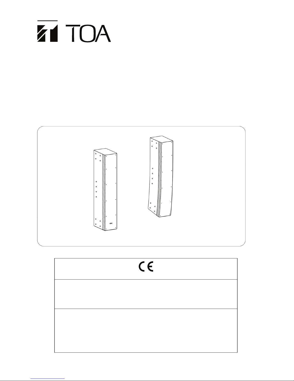
SR-S4LEB-Q
SR-S4SEB-Q
LINE ARRAY SPEAKERS
EXTENSION PLATE
(optional)
OPERATING INSTRUCTIONS
SR-S4LEB-Q
SR-S4SEB-Q
SR-EP4WP
Thank you for purchasing TOA‘s Line Array Speakers and their associated products.
Please carefully follow the instructions in this manual to ensure long, trouble-free use of your equipment.
1488
TOA Electronics Europe GmbH
Suederstrasse 282, 20537 Hamburg, Germany
1488-CPR-0570/W
16
DoP16-001
EN 54-24: 2008
Fire detection and fire alarm systems
-Part 24 : components of voice alarm systems - Loudspeakers
SR-S4LEB-Q/SR-S4SEB-Q
Type A
Technical data: see document SR-S4 Instruction Manual

2
TABLE OF CONTENTS
1. SAFETY PRECAUTIONS .......................................................................................... 3
2. GENERAL DESCRIPTION ........................................................................................ 5
3. FEATURES ..................................................................................................................... 5
4. INSTALLATION PRECAUTION ............................................................................... 6
5. COVERAGE AREA ...................................................................................................... 7
6. DIMENSIONAL DIAGRAM
6.1. Line Array Speaker SR-S4LEB-Q .............................................................................. 8
6.2. Line Array Speaker SR-S4SEB-Q ............................................................................... 8
7. SINGLE-AMPLIFIER DRIVE AND BI-AMPLIFIER DRIVE ............................... 9
8. INTERNAL WIRING DIAGRAM ................................................................................ 9
9. CHANGING TO HIGH IMPEDANCE ...................................................................... 10
10. JOINING SPEAKERS ................................................................................................. 11
11. CHANGING SINGLE-AMPLIFIER DRIVE
TO BI-AMPLIFIER DRIVE SYSTEM
...................................................................... 12
12. INTERNAL WIRING DIAGRAM
FOR THE BI-AMPLIFIER DRIVE SYSTEM
......................................................... 13
13. DIGITAL PROCESSOR FILTERING
13.1. Single-Amplier Drive (Factory-Setting) .................................................................... 13
13.2. Bi-Amplier Drive ...................................................................................................... 13
14. SPECIFICATIONS
14.1. Line Array Speaker SR-S4LEB-Q, SR-S4SEB-Q .................................................... 14
14.2. Extension Plate SR-EP4WP (optional) .................................................................... 15
WARNING
Indicates a potentially hazardous situation which, if mishandled, could
result in death or serious personal injury.
1. SAFETY PRECAUTIONS
• Before installation or use, be sure to carefully read all the instructions in this section for correct and safe operation.
• Be sure to follow all the precautionary instructions in this section, which contain important warnings and/or
cautions regarding safety.
• After reading, keep this manual handy for future reference.
Safety Symbol and Message Conventions
Safety symbols and messages described below are used in this manual to prevent bodily injury and property
damage which could result from mishandling. Before operating your product, read this manual rst and understand the safety symbols and messages so you are thoroughly aware of the potential safety hazards.
When Installing the Unit
• Avoid installing or mounting the unit in unstable locations, such as on a rickety table or a slanted surface.
Doing so may result in the unit falling down and causing personal injury and/or property damage.
• Refer all installation work to the dealer from whom the speaker was purchased. Installation requires extensive technical knowledge and experience. The speaker may fall off if incorrectly installed, resulting in possible
personal injury.
• Flying Precautions
Be sure to follow the instructions below. Otherwise, the suspension wires or belts may be off or snap and the
speaker may fall off, causing personal injury.
· Check to con rm that the suspension wires and belts are strong enough to withstand the speaker load.
· The connectors of the suspension wires and belts must be securely linked with those of the speaker.
· All parts and components (such as enclosures, metal pieces, and screws) must be free from any deformati-
on, crack, and corrosion.
· Be sure to use screws supplied with the optional ying hardware when installing the speaker using such
hardware.
• Install the unit only in a location that can structurally support the weight of the unit and the mounting bracket.
Doing otherwise may result in the unit falling down and causing personal injury and/or property damage.
• When installing the unit in the snowy area, take appropriate measures to prevent snow from lying on the unit.
If the snow lies on the unit, the unit may fall, causing personal injuries.
• Owing to the unit‘s size and weight, be sure that at least two persons are available to install the unit. Failure
to do so could result in personal injury.
• Do not use other methods than speci ed to install the speaker. Extreme force is applied to the unit and the
unit could fall off, possibly resulting in personal injuries.
• Use nuts and bolts that are appropriate for the ceiling‘s or wall‘s structure and composition. Failure to do so
may cause the speaker to fall, resulting in material damage and possible personal injury.
• Tighten each nut and bolt securely. Ensure that the bracket has no loose joints after installation to prevent
accidents that could result in personal injury.
• Use the speci ed mounting bracket in combination. Doing otherwise may cause the unit or component to fall
off, resulting in personal injury.
• Do not mount the unit in locations exposed to constant vibration. The mounting bracket can be damaged by
excessive vibration, potentially causing the unit to fall, which could result in personal injury.
3

CAUTION
Indicates a potentially hazardous situation which, if mishandled, could
result in moderate or minor personal injury, and/or property damage.
4
When Installing the Unit
• Avoid placing the unit in a doorway or other high traf c area as people may trip on the equipment and cords,
or be injured by falling objects.
• Avoid touching the unit‘s sharp metal edge to prevent injury.
When the Unit is in Use
• Do not operate the unit for an extended period of time with the sound distorting. This is an indication of a
malfunction, which in turn can cause heat to generate and result in a re.
• Do not stand or sit on, nor hang down from the unit as this may cause it to fall down or drop, resulting in
personal injury and/or property damage.
• Have the unit checked periodically by the shop from where it was purchased. Failure to do so may result
in corrosion or damage to the unit or its mounting bracket that could cause the unit to fall, possibly causing
personal injury.

2. GENERAL DESCRIPTION
Featuring slim construction, the SR-S4 series are 2-way line array speakers containing 32 speaker elements.
Zhe SRS4LEB-Q and SR-S4SEB-Q are intended for use in voice evacuation system applications. The sound
source speaker elements are vertically arranged in close proximity to each other, and form a continuous linear
sound source, achieving uniform sound pressure with less attenuation due to distance. The SR-S4LEB-Q speaker is of a linear design which is ideal for long distance sound transmission applications, while the SR-S4SEB-Q
features a curved line having a 10° vertical coverage area, and is designed to cover relatively short distance
and voice evacuation applications.
It is also possible to combine both the linear and curved line types to congure an array that continuously covers applications ranging from short to long distances.
3. FEATURES
• The SR-S4 EB-Q series is a 2-way line array speaker having eight 10 cm woofers for low-frequency output,
and 24 small tweeters for high-frequency sound output. Both the woofers and tweeters are arranged in the
front and rear on the same axis, providing a symmetrical, uniform coverage area.
• Since the linear sound source effect prevents energy from attenuating even at longer distances, the line array
speaker compares favorably with normal types of speakers in its ability to project sound long distances. This
realizes less difference in sound volume between areas close and far from the speaker, for a more uniform
sound eld.
• Since the speaker‘s vertical sound dispersion is suppressed, sound is only directed at the target area. The
speaker‘s construction is not inuenced by sound reection from ceiling or oor surfaces, and can provide
clear sounds even in spaces affected by long reverberation times or other poor acoustic conditions.
• Since the attenuation of sound pressure is small even far away from the speaker, the volume is not excessively loud in the area near the speaker. This helps suppress feedback (improving safety amplication gain).
• By joining 2 or 3 speakers, a longer sound source can be congured, making it possible to project sound output farther and at larger volumes.
• The speaker has a built-in network circuit for a single amplier drive. Changing the internal connector position
enables bi-amplier drive that provides a higher quality sound output.
• The use of optional SR-WB4WP Wall mounting bracket and SR-TB4WP Wall tilt bracket permits the speaker
to be installed in the most appropriate position for its intended use. (Details of the installation procedures are
described in the installation manual enclosed with each bracket.)
• The speaker can be used for high-impedance applications with the additional use of the optional MT-S0601
matching transformer (internal mount) or MT-200 (external mounting). A matching transformer requires a single-amplier drive.
5
 Loading...