

Toa SR-MF1B, SR-MF1W, SR-ML1B, SR-ML1W Operating Instructions Manual
OPERATING INSTRUCTIONS
MECHANICALLY STEERABLE
LINE ARRAY SPEAKER SYSTEM
SR-MF1B
SR-MF1W
SR-ML1B
SR-ML1W
SR-MF1B
SR-MF1W
SR-ML1B
SR-ML1W
Thank you for purchasing TOAʼs Mechanically Steerable Line Array Speaker System.
Please carefully follow the instructions in this manual to ensure long, trouble-free use of your equipment.

2
TABLE OF CONTENTS
1. SAFETY PRECAUTIONS ............................................................................................ 3
2. GENERAL DESCRIPTION .......................................................................................... 5
3. FEATURES ...................................................................................................................... 5
4. ANGLE ADJUSTMENT ................................................................................................ 6
5. COVERAGE AREA ....................................................................................................... 7
6. AMPLIFIER CONFIGURATIONS .............................................................................. 8
7. JOINING SPEAKERS ................................................................................................. 10
8. INSTALLATIONS
8.1. Wall mounting (using the SR-MB1(B/W)) .................................................................... 12
8.2. Mounting dimensions of bracket bases ........................................................................ 13
8.3. Wall mounting (using the SR-PB1(B/W)) ..................................................................... 14
8.4. Ceiling-suspended mounting (using the SR-HB1(B/W)) .............................................. 15
9. DIGITAL PROCESSOR FILTERING
9.1. Single-Amplifier Drive with 1 SR-MF1(B/W) and 1 SR-ML1(B/W) .............................. 16
9.2. Single-Amplifier Drive with 1 SR-MF1(B/W) and 2 SR-ML1(B/W)s ............................ 16
9.3. Bi-Amplifier Drive with 1 SR-MF1(B/W) and 1 SR-ML1(B/W) ..................................... 16
9.4. Bi-Amplifier Drive with 1 SR-MF1(B/W) and 2 SR-ML1(B/W)s ................................... 16
10. DIMENSIONAL DIAGRAM
10.1. SR-MF1(B/W)............................................................................................................. 17
10.2. SR-ML1(B/W) ............................................................................................................. 17
11. SPECIFICATIONS ........................................................................................................ 18
3
1. SAFETY PRECAUTIONS
• Before installation or use, be sure to carefully read all the instructions in this section for correct and safe
operation.
• Be sure to follow all the precautionary instructions in this section, which contain important warnings and/or
cautions regarding safety.
• After reading, keep this manual handy for future reference.
Safety Symbol and Message Conventions
Safety symbols and messages described below are used in this manual to prevent bodily injury and property
damage which could result from mishandling. Before operating your product, read this manual first and
understand the safety symbols and messages so you are thoroughly aware of the potential safety hazards.
Indicates a potentially hazardous situation which, if mishandled, could
result in death or serious personal injury.
WARNING
When Installing the Unit
• Avoid installing or mounting the unit in unstable locations, such as on a rickety table or a slanted surface.
Doing so may result in the unit falling down and causing personal injury and/or property damage.
• Since the unit is designed for in-door use, do not install it outdoors. If installed outdoors, the aging of parts
causes the unit to fall off, resulting in personal injury. Also, when it gets wet with rain, there is a danger of
electric shock.
• Refer all installation work to the dealer from whom the speaker was purchased. Installation requires
extensive technical knowledge and experience. The speaker may fall off if incorrectly installed, resulting in
possible personal injury.
• Flying Precautions
Be sure to follow the instructions below. Otherwise, the suspension wires or belts may be off or snap and
the speaker may fall off, causing personal injury.
· Check to confirm that the suspension wires and belts are strong enough to withstand the speaker load.
· The connectors of the suspension wires and belts must be securely linked with those of the speaker.
· All parts and components (such as enclosures, metal pieces, and screws) must be free from any
deformation, crack, and corrosion.
· Be sure to use screws supplied with the optional flying hardware when installing the speaker using such
hardware.
• Install the unit only in a location that can structurally support the weight of the unit and the mounting bracket.
Doing otherwise may result in the unit falling down and causing personal injury and/or property damage.
• Owing to the unit's size and weight, be sure that at least two persons are available to install the unit. Failure
to do so could result in personal injury.
• Do not use other methods than specified to install the speaker. Extreme force is applied to the unit and the
unit could fall off, possibly resulting in personal injuries.
• Use nuts and bolts that are appropriate for the ceiling's or wall's structure and composition. Failure to do so
may cause the speaker to fall, resulting in material damage and possible personal injury.
• Tighten each nut and bolt securely. Ensure that the bracket has no loose joints after installation to prevent
accidents that could result in personal injury.
• Use the specified mounting bracket in combination. Doing otherwise may cause the unit or component to fall
off, resulting in personal injury.
• Do not mount the unit in locations exposed to constant vibration. The mounting bracket can be damaged by
excessive vibration, potentially causing the unit to fall, which could result in personal injury.

4
When Installing the Unit
• Avoid placing the unit in a doorway or other high traffic area as people may trip on the equipment and cords,
or be injured by falling objects.
• Avoid touching the unit's sharp metal edge to prevent injury.
• When installing the speaker, be sure to handle it with two or more persons. Falling or dropping the unit may
cause personal injury and/or property damage.
When the Unit is in Use
• Do not operate the unit for an extended period of time with the sound distorting. This is an indication of a
malfunction, which in turn can cause heat to generate and result in a fire.
• Do not stand or sit on, nor hang down from the unit as this may cause it to fall down or drop, resulting in
personal injury and/or property damage.
• Have the unit checked periodically by the shop from where it was purchased. Failure to do so may result in
corrosion or damage to the unit or its mounting bracket that could cause the unit to fall, possibly causing
personal injury.
Indicates a potentially hazardous situation which, if mishandled, could
result in moderate or minor personal injury, and/or property damage.
CAUTION

5
2. GENERAL DESCRIPTION
The Mechanically Steerable Line Array Speaker System consists of the SR-MF1(B/W) [Mechanically
Steerable Array Speaker] and the SR-ML1(B/W) [Low Frequency Expand Speaker]. A single SR-MF1(B/W) or
combination systems with SR-ML1(B/W) can be used. The key feature is that the tilt and dispersion angles of
the SR-MF1(B/W) are mechanically and manually adjustable. This provides a valuable solution for the spaces
where the speakers need to aim at downward seating/audience areas while they are mounted perpendicularly
to the wall.
3. FEATURES
• The SR-MF1(B/W) mounts the angle adjustment component with eight 2” drivers on its cabinet, which allows
manual adjustment of the tilt angle from 0 ° or -3 °, and the dispersion angle from 10 °, 15 °, 20 °, 25 °, or 30 °.
• Adding the SR-ML1(B/W) equipped with four 3.5” drivers to the system, achieves a more powerful lowfrequency sound.
• Multiple system configurations can be established with the SR-MF1(B/W) as a full-range speaker and the
SR-ML1(B/W) as an expansion low frequency speaker; from a single SR-MF1(B/W), to the combination of 1
SR-MF1(B/W) and 2 SR-ML1(B/W)s.
• Since the linear sound source effect prevents acoustical energy from attenuating even at longer distances,
the line array speaker provides advantages compared with normal types of speakers in its ability to project
sound long distances. The difference in sound volume between the distance from the speaker provides a
more uniform sound field.
• Since the speaker's vertical sound dispersion is focused, sound is only directed at the target area. The line
array speaker (when correctly positioned) is not influenced by sound reflection from ceiling or floor surfaces,
and can provide clear sounds even in spaces affected by long reverberation, or other poor acoustic
conditions.
• If the attenuation of sound pressure is low even far away from the speaker, the volume is not excessively
loud in the area near the speaker. This helps suppress feedback (improving microphone amplification gain).
• A variety of optional mounting brackets are available for several applications.
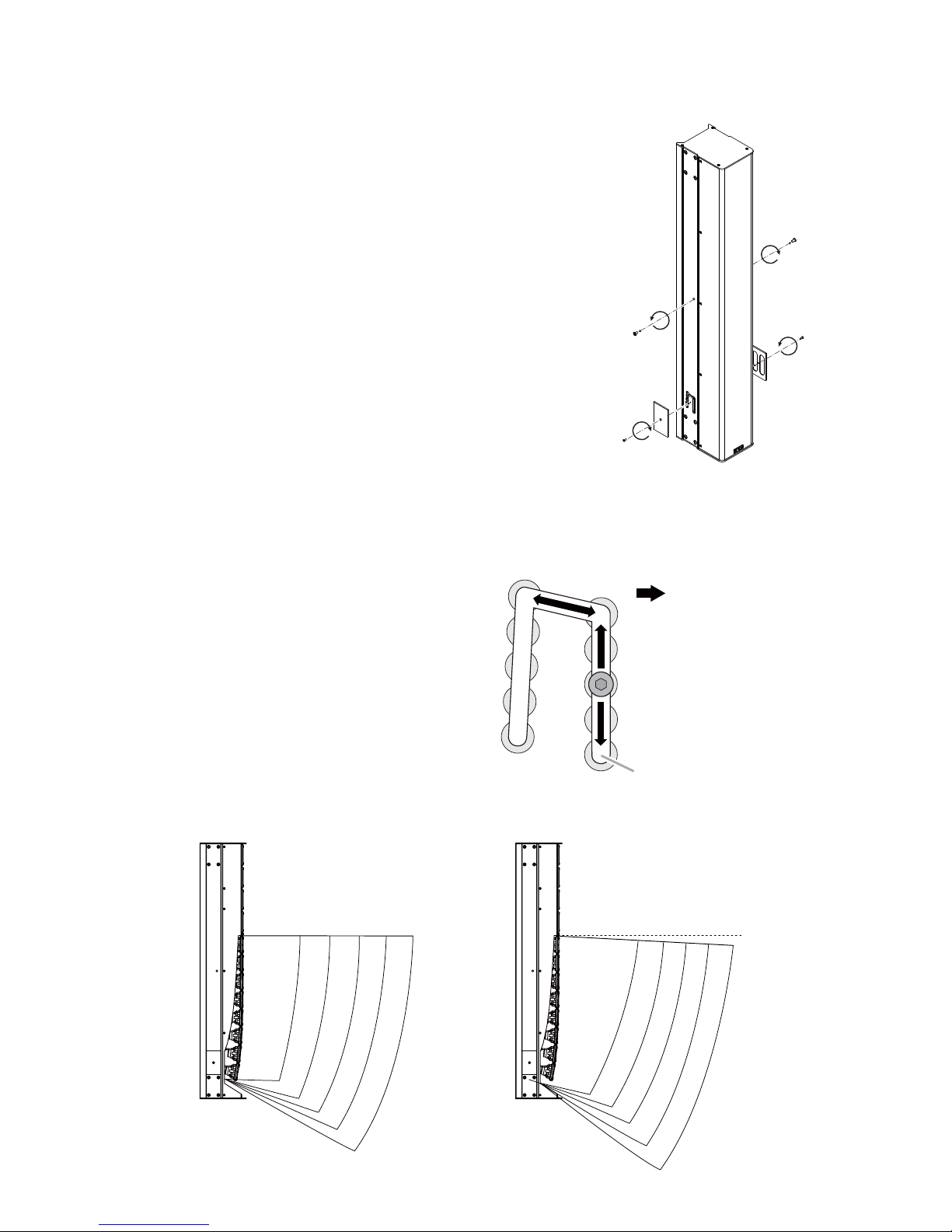
4. ANGLE ADJUSTMENT
Shifting the angle adjustment bolts mounted on both side of SRMF1(B/W) allows adjusting its tilt and dispersion angle by multiple steps.
[Adjustment Procedure]
Step 1. Remove the hex head bolts on both side of the cabinet for
releasing the angle adjustment component.
The removed screws are used only when shipping.
Step 2. Loosen the hex head bolts mounted on the adjustment
component with a hex wrench, and shift them into the desired
position.
Step 3. Replace the hex head bolts with the supplied smaller-head
bolts one by one and tighten them.
Step 4. Attach the cover plates on with the supplied screws.
Note: When shipping the SR-MF1(B/W), the original hex head bolts
must be attached while the angle adjustment blots being set at
the default position for protecting the component.
[Adjustment Patterns]
Adjustment component allows selecting the
tilt angle from 2 steps and dispersion angle by
5 steps.
[Coverage images]
6
1
4
4
1
Tilt = 0° Tilt = -3°
0°
-3°
10°
10°
15°
20°
25°
30°
15°
20°
25°
30°
(Tilt Angle)
0°
-3°
30°
25°
20°
15°
10°
Wider
(Dispersion Angle)
Narrower
Default position
Front side of the cabinet
• Bolt positions and angles
 Loading...