

Page 1
OPERATING INSTRUCTIONS
SPEAKER SYSTEM
SUBWOOFER SYSTEM
SR-F1D
SR-L1B
SR-F1D SR-L1B
Please follow the instructions in this manual to obtain the optimum results from this unit.
We also recommend that you keep this manual handy for future reference.
Page 2

2
TABLE OF CONTENTS
1. SAFETY PRECAUTIONS ............................................................................... 3
2. GENERAL DESCRIPTION ............................................................................. 5
3. FEATURES .......................................................................................................... 5
4. INSTALLING THE SR-F1D ON THE SR-L1B ........................................... 5
5. FLYING (SR-F1D ONLY)
5.1. Direct Suspension Using the SR-F1D's Flying Hardware ................................. 6
5.2. Suspension Using Optional Flying Hardware
5.2.1. SR-F1D speaker flying hardware system ............................................... 7
5.2.2. Flying precautions ................................................................................... 8
5.2.3. Flying example ........................................................................................ 8
6. SPEAKER STAND FOR SR-F1D ................................................................. 9
7. INPUT CONNECTOR ...................................................................................... 10
8. CONNECTION DIAGRAMS
8.1. Single System (SR-F1D) .................................................................................. 10
8.2. Combination System (SR-F1D and SR-L1B) ................................................... 10
9. PROCESSOR SETTINGS .............................................................................. 11
9.1. Flat Phase Type ............................................................................................... 12
9.2. Minimum Delay Type ....................................................................................... 13
10. CHARACTERISTIC DIAGRAMS
10.1. SR-F1D + SR-L1B (when DP-0206 is used)
10.1.1. Flat phase type .................................................................................. 14
10.1.2. Minimum delay type ........................................................................... 14
10.2. SR-F1D (when DP-0206 is used) .................................................................. 15
11. DIMENSIONAL DIAGRAMS ......................................................................... 15
12. SPECIFICATIONS ............................................................................................ 16
Page 3
3
When Installing the Unit
• Avoid installing or mounting the unit in unstable
locations, such as on a rickety table or a slanted
surface. Doing so may result in the unit falling
down and causing personal injury and/or property
damage.
• Refer all installation work to the dealer from whom
the speaker was purchased. Installation for flying
requires extensive technical knowledge and
experience. The speaker may fall off if incorrectly
installed, resulting in possible personal injury.
• Flying Precautions
Be sure to follow the instructions below. Otherwise,
the suspension wires or belts may be off or snap
and the speaker may fall off, causing personal
injury.
· Check to confirm that the suspension wires and
belts are strong enough to withstand the speaker
load.
· The connectors of the suspension wires and belts
must be securely linked with those of the
speaker.
· All parts and components (such as enclosures,
metal pieces, and screws) must be free from any
deformation, crack, and corrosion.
· Be sure to use screws supplied with the optional
flying hardware when installing the speaker using
such hardware.
• Install the unit only in a location that can
structurally support the weight of the unit and the
mounting bracket. Doing otherwise may result in
the unit falling down and causing personal injury
and/or property damage.
• Owing to the unit's size and weight, be sure that at
least two persons are available to install the unit.
Failure to do so could result in personal injury.
• Do not use other methods than specified to mount
the bracket. Extreme force is applied to the unit
and the unit could fall off, possibly resulting in
personal injuries.
• Tighten each nut and bolt securely. Ensure that the
bracket has no loose joints after installation to
prevent accidents that could result in personal
injury.
• Use the specified mounting bracket in combination.
Doing otherwise may cause the unit or component
to fall off, resulting in personal injury.
• Cautions when using the speaker stand
Be sure to carefully observe the following
instructions. Ignoring them could result in the
speaker system toppling over or falling down,
possibly resulting in personal injury.
· Open the stand legs to their full extension.
· Do not extend or fold the tripod while the speaker
is mounted.
· Install the stand on a flat, hard surface.
· Avoid placing the speaker in a doorway or other
high-traffic area where people may trip over the
equipment or cords.
· In outdoor installations, take such measures as
securing speakers with safety wire to prevent
them from being toppled over due to strong wind,
etc.
1. SAFETY PRECAUTIONS
• Be sure to read the instructions in this section carefully before use.
• Make sure to observe the instructions in this manual as the conventions of safety symbols and messages
regarded as very important precautions are included.
• We also recommend you keep this instruction manual handy for future reference.
Safety Symbol and Message Conventions
Safety symbols and messages described below are used in this manual to prevent bodily injury and property
damage which could result from mishandling. Before operating your product, read this manual first and
understand the safety symbols and messages so you are thoroughly aware of the potential safety hazards.
WARNING
Indicates a potentially hazardous situation which, if mishandled, could
result in death or serious personal injury.
Indicates a potentially hazardous situation which, if mishandled, could
result in moderate or minor personal injury, and/or property damage.
WARNING
CAUTION
Page 4

4
When Installing the Unit
• When unpacking or moving the unit, be sure to
handle it with two or more persons. Falling or
dropping the unit may cause personal injury and/or
property damage.
When the Unit is in Use
• Do not operate the unit for an extended period of
time with the sound distorting. This is an indication
of a malfunction, which in turn can cause heat to
generate and result in a fire.
• Do not stand or sit on, nor hang down from the unit
as this may cause it to fall down or drop, resulting
in personal injury and/or property damage.
• Have the unit checked periodically by the shop
from where it was purchased. Failure to do so may
result in corrosion or damage to the unit or its
mounting bracket that could cause the unit to fall,
possibly causing personal injury.
CAUTION
Page 5
5
2. GENERAL DESCRIPTION
Developed for the mobile sound reinforcement applications, TOA's SR-F1D and SR-L1B make up a speaker
and subwoofer system which features high power handling capability, high quality and durable construction.
3. FEATURES
• The SR-F1D can reproduce both low and high frequencies (bi-amp operation), while the SR-L1B clearly
reproduces super-low frequencies. Both systems are used in conjunction with the DP-0206 Digital
Processor.
• The SR-F1D reproduces low frequencies with excellent transient response thanks to its high-efficiency
30 cm woofer with large 20 cm diameter magnet.
• The SR-F1D's driver employs a titanium diaphragm and features high sound quality and high power handling
capability. Its constant directivity horn (60° horizontal x 40° vertical) has a smoothed cross-sectional area
and provides a uniform sound field and smooth sound quality.
• The SR-L1B's 38 cm woofer consists of a strong magnetic circuit employing a large 20 cm diameter magnet
and a 72 mm diameter long voice coil. This combination permits ultra-linearity down to super-low
frequencies while realizing high power handling capability.
• The enclosure is constructed of high-strength Apiton plywood. Since the outside surface is covered in FRP
(glass fiber-reinforced plastic), the speaker also features high durability to stand up to rough handling when
used on the road.
• NEUTRIK NL4MPR input connectors ensure quick and accurate system field installations.
• The SR-F1D features flying hardware (Aeroquip ring/stud pan fittings) installed on its top and bottom. The
bottom surface is also equipped with built-in nuts for mounting on an optional stand.
• Because the sides of the SR-F1D's enclosure are angled at 15°, when multiple speakers are arranged sideby-side, they can be oriented in a radial array, which helps suppress mutual interference at high frequencies.
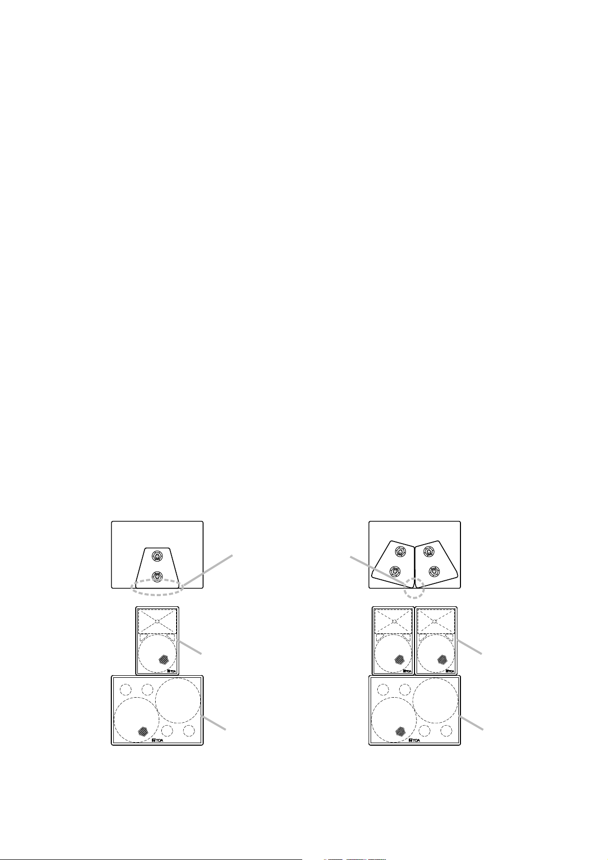
4. INSTALLING THE SR-F1D ON THE SR-L1B
• When one SR-F1D is installed
on the SR-L1B
Align with the front surface
of the SR-L1B.
SR-F1D
SR-L1B
• When two SR-F1Ds are
installed on the SR-L1B
SR-F1D
SR-L1B
Page 6

6
5. FLYING (SR-F1D ONLY)
Two flying methods can be performed: 1) direct suspension using the SR-F1D's flying hardware (refer to the
figures below), and 2) suspension using optional flying hardware (refer to p. 7).
• Be sure to refer flying construction work to the dealer from whom the speaker was purchased.
• Avoid flying methods other than those described in this section.
Otherwise, the suspension wires or belts may be off or snap and the speaker may fall off, causing
personal injury.
Shown below are the general flying methods:
• Use the pan fitting rings attached to the speaker's top and/or bottom.
• Provide at least two suspension points on each speaker's top.
• The maximum number of speakers that can be suspended vertically
is three.
WARNING
Do not suspend as illustrated below:
5.1. Direct Suspension Using the SR-F1D's Flying Hardware
SR-F1D's flying hardware
• Use of a single wire that
has formed a loop
• Flying through handles.
• Flying through only one
suspension point on the
top.
• Flying using the nuts on
the bottom surface
• Vertical suspension of 4 or
more speakers.
Page 7

7
5.2. Suspension Using Optional Flying Hardware
5.2.1. SR-F1D speaker flying hardware system
The speaker flying hardware system is manufactured by ATM FLY-WARETM(ATM GROUP, Inc.) of the United
States for use with TOA's SR-F1D speaker. The flying system permits various speaker array configurations to
be constructed quickly and safely without using special components.
[System composition]
The flying system comprises 5 main components.
AMFS-SRF1-TH Truss Module
Allowable load 275 kg
The truss module attaches to both the top and
bottom of the SR-F1D speaker.
Note
Bolts, nuts, and other fixing hardware are included.
AMFS-1X2-30 Connecting Bar
Allowable load 278 kg
Used for horizontal speaker connection.
AMFS-1X2-SME Shackle Mount
Allowable load 225 kg
Used to set suspension points for vertical speaker
suspension. (Upper and lower speakers can be
suspended at different tilt angles.)
AMFS-1X2-SB Stacking Bracket
Allowable load 194 kg
Used to suspend multiple speakers connected close
to each other.
2.5QRP Quick Release Pin
Allowable load 835 kg
Has a lock function and connects individual parts
surely and quickly.
[Mounting truss module]
Use 2 pan fitting rings on the SR-F1D's top or bottom to
mount the truss module. Pass a hexagonal bolt*
through the module and pan fitting ring, then secure it
with a wedge*, spring washer*, and nut*.
* Supplied with the truss module
Be sure to use the supplied hardware when
mounting the truss module. The speaker may fall
off if other hardware is used, resulting in possible
personal injury.
WARNING
1
2
3
4
3
5
1
2
4
5
Pan fitting ring
(at top and bottom of SR-F1D)
Truss module
Nut 3/8''
Spring washer 3/8''
Wedge
Hexagon bolt 3/8'' x 41/2''
Page 8

8
5.2.2. Flying precautions
• Confirm the following points before installation.
1. Load on each flying hardware component does not exceed its allowable load.
2. All quick release pins (2.5QRP) are fully inserted into other components and locked.
3. All components used in suspension (i.e. enclosures, individual flying hardwares, clamps, connectors, and
suspension devices) are free from any deformation, crack and corrosion.
• The maximum number of speakers that can be suspended per shackle mount (AMFS-1X2-SME) or stacking
bracket (AMFS-1X2-SB) is four.
• Not more than three speakers are joined and suspended vertically.
5.2.3. Flying example
[Speaker array arranged in 2 speakers horizontal
x 3 rows vertical (6 speakers in total)]
[Speaker array assembly diagram]
1
5
3
2
4
[Hardware to be used]
1
Truss Module AMFS-SRF1-TH: 12
2
Connecting Bar AMFS-1X2-30: 6
3
Shackle Mount AMFS-1X2-SEM: 6
4
Stacking Bracket AMFS-1X2-SB: 4
5
Quick Release Pin 2.5QRP: 26
Note
For mounting truss module, refer to
the previous page.
Page 9

9
6. SPEAKER STAND FOR SR-F1D
The speaker stand manufactured by Köning & Meyer GMBH (K & M) of Germany is made available for use
with TOA's SR-F1D speaker.
The speaker stand consists of two main sections, which are sold separately.
Stand: Model 213
Bracket: Model 19582
Step 1. Extend the stand's legs.
Loosen the tripod fixing screw and open the tripod
legs outward so that the stays become level.
Then, tighten the fixing screw.
Fully extend the stand's tripod legs and place
the stand on a stable surface. If the tripod is
not sufficiently extended, the stand could
topple over, possibly resulting in personal
injury.
WARNING
Step 4. Adjust the stand height.
4-1. Loosen the height fixing screw.
4-2. Loosen the handle fixing screw and raise the
handle, then retighten the handle screw.
4-3. While holding down the lock button, adjust the
speaker's height by turning the height adjustment
handle. (Clockwise rotation raises the speaker.)
Note
You cannot rotate the handle unless the lock button
is continuously pressed. To complete the height
adjustment, ensure that the shaft is locked when
the lock button is released. (This can be checked
by rotating the handle slightly.)
Step 5. Retighten the height fixing screw.
Note
Leave the handle folded back except when adjusting the
height.
Owing to the speaker's size and weight, be
sure that at least two persons are available to
install the speaker. Failure to do so could result
in personal injury.
WARNING
Step 2. Attach the stand bracket to the speaker using the
speaker mounting screws and plain washers.
Step 3. Loosen the bracket fixing screw, then place the
speaker on the stand.
After setting the speaker's orientation, retighten the
bracket fixing screw.
SR-F1D
Bracket fixing
screw
Stand bracket
19582
Plain washer
2
Speaker mounting screw
3
Lock botton
Height fixing screw
Handle fixing screw
Height adjustment
handle
4, 5
Stand 213
Tripod fixing screw
Tripod leg
1
Stay
Storage of speaker mounting screws
Speaker mounting screw
Plain washer
Treaded hole
Tip
To avoid the loss of the speaker mounting
screws, it is highly recommended that the
screws be inserted into the stand bracket
when putting away the stand.
Page 10

10
7. INPUT CONNECTOR
• Each speaker employes the NEUTRIK NL4MPR connector for its input. The mated cable connector is the
NEUTRICK NL4FC.
• Pins of the NEUTRIK connector are connected as shown in the table below.
* The "left" and the "right" are the positions of
woofer units as viewed from the front.
Pin number SR-F1D SR-L1B
1 + LOW + Left* +
1 – LOW – Left* –
2 + HIGH + Right* +
2 – HIGH – Right* –
8. CONNECTION DIAGRAMS
• It is recommended that TOA's IP-600D Power Amplifier be connected and used.
• The DP-0206 Digital Processor's compressor has been set based on a power amplifier gain of "20 dB."
When using the IP-600D amplifier, set the input volume control to the "–12 dB" position.
8.1. Single System (SR-F1D)
8.2. Combination System (SR-F1D and SR-L1B)
SR-L1B
Left
Right
HIGH
IN
Mixer/Preamplifier
Digital processor
DP-0206
LOW
Power amplifier
SR-F1D
Digital processor
DP-0206
IN
Mixer/Preamplifier
HIGH
LOW
SR-F1D
Power amplifier
SUB-LOW
Power amplifier
SR-L1B
Page 11

11
9. PROCESSOR SETTINGS
Set the following parameters – for the DP-0206 Digital Processor. Perform settings for either the "flat
phase type" (p. 12) or "minimum delay type" (p. 13) depending on the application.
Note
Refer to the DP-0206 Software Instruction Manual for setting instructions.
10
1
1
2
3
4
5
6
7
8
9
10
Page 12

12
9.1. Flat Phase Type
• Phase characteristics for the driver's band are nearly flattened using all-pass filters (APF).
• Set parameters – for the DP-0206 as follows:
10
1
* The DP-0206 Digital Processor's compressor has been set based on a power amplifier gain of "20 dB."
When using the IP-600D amplifier, set the input volume control to the "–12 dB" position.
• In the above parameter setting, the polarity checker indication for each frequency band is as follows:
Polarity
SR-L1B Negative
SR-F1DLOW Positive
SR-F1DHIGH Positive
1
INPUT 1
1 1.25 k –5.0 1.414
2 1.80 k –3.0 4.318
3 2.90 k –0.5 4.318
4 3.75 k –4.0 4.318
5 5.40 k –4.0 4.318
PEQ
Freq. Gain Q
2
X-over
Freq.Type
HPF
LPF 6 dB 29
Gain Polarity Delay
8.5 Inverse
3
X-over
Freq.Type
12 dB BW
HPF
LPF
24 dB BS
700
Gain Polarity Delay
0 Normal
4
X-over
Freq.Type
HPF
LPF
12 dB BW
900
Gain Polarity Delay
–5.5 Inverse
20
QQ2
0.667
QQ2
0.5
QQ2
0
5
Filter
Type
12LPF (6 dB)
Low Shelving
Freq. Gain
330
40 2.5
Q
6
Filter
Type
1 PEQ 95 –1.5 4.318
2 PEQ 462 –1.5 4.318
3 PEQ 1.80 k –12.0 9.889
4 PEQ 2.00 k –2.0 4.608
Freq. Gain Q
7
Filter
Type
1
PEQ 13.6 k 7.5 1.414
2
All Pass 2.94 k 1.414
3
All Pass 3.87 k 1.119
4
All Pass 5.00 k 2.871
5
All Pass 6.90 k 4.608
6
All Pass 8.40 k 4.318
7
All Pass 9.95 k 5.764
8
All Pass 11.6 k 7.689
9
All Pass 13.1 k 9.889
10
All Pass 14.6 k 6.919
Freq. Gain
Q
8
Comp.
Thresh
Ratio
Sync
Attack
Release
9
Comp.
Thresh
Ratio
Sync
Attack
Release
10
Comp.
Thresh
Ratio
Sync
Attack
Release
*
13
4 : 1
off
20
200
*
10
2 : 1
off
10
100
*
15
4 : 1
off
10
100
OUTPUT 1
SR-L1B
SUB-LOW
OUTPUT 2
SR-F1D
LOW
OUTPUT 3
SR-F1D
HIGH
Page 13

13
9.2. Minimum Delay Type
• Designed to provide a minimum signal delay without using a delay function or APF for each frequency band.
• Set parameters – for the DP-0206 as follows:
10
2
* The DP-0206 Digital Processor's compressor has been set based on a power amplifier gain of "20 dB."
When using the IP-600D amplifier, set the input volume control to the "–12 dB" position.
• In the above parameter setting, the polarity checker indication for each frequency band is as follows:
Polarity
SR-L1B Negative
SR-F1DLOW Positive
SR-F1DHIGH Negative
INPUT 1
2
X-over
Freq.Type
HPF
LPF 6 dB 30
Gain Polarity Delay
8.5 Inverse 0
3
X-over
Freq.Type
HPF
12 dB BW
24 dB BS
LPF
Gain Polarity Delay
20
702
0 Normal
4
X-over
Freq.Type
HPF
12 dB BW
LPF
900
Gain Polarity Delay
–5.5 Normal
QQ2
QQ2
0
QQ2
0
5
Filter
Type
12LPF (6 dB)
Low Shelving
Freq. Gain
330
40 2.5
Q
6
Filter
Type
12PEQ
PEQ
34PEQ
PEQ
5 PEQ 2.00 k –2.0
Freq. Gain Q
131
–2.0 4.318
275 –2.0
380
1.80 k –12.0
4.318
–3.0 8.651
9.889
4.608
7
Filter
Type
High Shelving
1
2
PEQ
3 PEQ 1.40 k –5.0 1.414
4 PEQ 2.90 k –1.0 4.318
5 PEQ 3.75 k –4.0 4.318
6 PEQ 5.30 k –4.0 4.318
7 PEQ 13.2 k 7.5 2.016
8 PEQ 15.0 k 3.0 4.318
Freq. Gain
16.0 k
1.00 k –2.0 4.318
5.0
Q
8
Comp.
Thresh
Ratio
Sync
Attack
Release
9
Comp.
Thresh
Ratio
Sync
Attack
Release
10
Comp.
Thresh
Ratio
Sync
Attack
Release
*
13
4 : 1
off
20
200
*
10
2 : 1
off
10
100
*
15
4 : 1
off
10
100
OUTPUT 1
SR-L1B
SUB-LOW
OUTPUT 2
SR-F1D
LOW
OUTPUT 3
SR-F1D
HIGH
Page 14

14
k
k
10. CHARACTERISTIC DIAGRAMS
Note: Referenced to 200 Hz in the SR-F1D's LOW band, 1 W 1 m
10.1. SR-F1D + SR-L1B (when DP-0206 is used)
10.1.1. Flat phase type
10.1.2. Minimum delay type
Phase Characteristics
Frequency Characteristics
Frequency Characteristics
Phase Characteristics
[dB]
110
100
90
SPL
80
70
60
20 50 100 500 1 k 5 k 10 k 20 k
[deg]
180
90
0
Phase
–90
–180
20 50 100 500
Frequency
1 k 5 k 10 k 20
Frequency
SR-F1D + SR-L1B
SR-L1B
SR-F1D LOW
SR-F1D HIGH
[Hz]
[Hz]
[dB]
110
100
90
SPL
80
70
60
20 50 100 500 1 k 5 k 10 k 20 k
[deg]
180
90
0
Phase
–90
–180
20 50 100 500 1 k 5 k 10 k 20
Frequency
Frequency
SR-F1D + SR-L1B
SR-L1B
SR-F1D LOW
SR-F1D HIGH
[Hz]
[Hz]
Page 15

15
10.2. SR-F1D (when DP-0206 is used)
[Polar pattern]
Horizontal Vertical
11. DIMENSIONAL DIAGRAMS
Unit: mm
0°
–10
–20
–30
–40
–40
–30
–20
–10
10
0
0
10
180°
330°
210°
300°
240°
270°
60°
90°
120°
30°
60°
90°
120°
150°
30°
150°
–10
–20
–30
–40
–40
–30
–20
–10
10
0
0
10
180°
HornWoofer
0°
330°
300°
270°
240°
1,000 Hz
210°
2,000 Hz
4,000 Hz
8,000 Hz
[SR-F1D] [SR-L1B]
221
364
390
619
224
120
2-M8 Nut (For mounting to an optional speaker stand)
629
829 606
Page 16

12. SPECIFICATIONS
Enclosure Bass reflex type
Power Handling Continuous pink noise: 120 W (Low frequency)*1, 80 W (High frequency)*
2
Capacity Continuous program: 360 W (Low frequency), 240 W (High frequency)
Rated Impedance Low frequency: 8 Ω, High frequency: 16 Ω
Sensitivity Low frequency: 98 dB (1 W, 1 m), High frequency: 110 dB (1 W, 1 m)
Frequency Response 70 – 20,000 Hz at DP-0206's use
Crossover Frequency 1,000 Hz at DP-0206's use
Speaker Component Low frequency: One 30 cm dia. cone-type
High frequency: CD horn (60° horizontal by 40° vertical) plus compression driver
Input Connector NEUTRIK NL4MPR
Finish Enclosure: FRP coating, gray
Front grill: Black, paint
Dimensions 390 (w) x 619 (h) x 364 (d) mm
Weight 37 kg
Printed in Japan
133-01-431-60
[SR-F1D]
*
1
Band limited (50 – 1,000 Hz) pink noise signal (24 hrs.)
*2Band limited (1,000 – 20,000 Hz) pink noise signal (24 hrs.)
*3Band limited (40 – 1,000 Hz) pink noise signal (24 hrs.)
Note: The design and specifications are subject to change without notice for improvement.
Enclosure Bass reflex type
Power Handling Continuous pink noise: 150 W x 2*
3
Capacity Continuous program: 450 W x 2
Rated Impedance 8 Ω x 2
Sensitivity 96 dB (0.5 W x 2, 1 m)
Frequency Response 35 – 1,000 Hz
Crossover Frequency 125 Hz at DP-0206's use
Speaker Component Two 30 cm dia. cone speakers
Input Connector NEUTRIK NL4MPR
Finish Enclosure: FRP coating, gray
Front grill: Black, paint
Dimensions 829 (w) x 629 (h) x 606 (d) mm
Weight 79 kg
[SR-L1B]
 Loading...