

Page 1

OPERATING INSTRUCTIONS
SPEAKER SYSTEM
SR-F09, SR-F09-V1
SR-F09-V2, SR-F09-V3
SR-L09, SR-L05
Thank you for purchasing TOA's Speaker System.
Please carefully follow the instructions in this manual to ensure long, trouble-free use of your equipment.
TABLE OF CONTENTS
1. SAFETY PRECAUTIONS ................................................................................. 2
2. GENERAL DESCRIPTION .............................................................................. 3
3. FEATURES ........................................................................................................... 3
4. DIMENSIONAL DIAGRAM .............................................................................. 4
5. WIRING DIAGRAMS ......................................................................................... 4
6. INPUT CONNECTORS ..................................................................................... 5
7. CONNECTIONS .................................................................................................. 5
8. FLYING ................................................................................................................... 6
9. DIGITAL PROCESSOR SETTINGS ............................................................. 7
10. SPEAKER STAND FOR SR-F09 AND SR-F09-V1 .................................. 8
11. CHANGE FROM SINGLE- TO BI-AMPLIFIER DRIVE ........................... 9
12. SPECIFICATIONS ............................................................................................ 12
Accessory ................................................................................................................ 12
Page 2
2
1. SAFETY PRECAUTIONS
• Before installation or use, be sure to carefully read all the instructions in this section for correct and safe
operation.
• Be sure to follow all the precautionary instructions in this section, which contain important warnings and/or
cautions regarding safety.
• After reading, keep this manual handy for future reference.
Safety Symbol and Message Conventions
Safety symbols and messages described below are used in this manual to prevent bodily injury and property
damage which could result from mishandling. Before operating your product, read this manual first and
understand the safety symbols and messages so you are thoroughly aware of the potential safety hazards.
When Installing the Unit
• Refer all installation work to the dealer from whom
the speaker was purchased. Installation for flying
requires extensive technical knowledge and
experience. The speaker may fall off if incorrectly
installed, resulting in possible personal injury.
• Install the unit only in a location that can
structurally support the weight of the unit and the
mounting bracket. Doing otherwise may result in
the unit falling down and causing personal injury
and/or property damage.
• Flying Precautions (SR-F09, SR-F09-V1, SR-F09V2, SR-F09-V3)
Be sure to follow the instructions below.
Otherwise, the suspension wires or belts may be
off or snap and the speaker may fall off, causing
personal injury.
· Check to confirm that the suspension wires and
belts are strong enough to withstand the speaker
load.
· The connectors of the suspension wires and belts
must be securely linked with those of the
speaker.
· All parts and components (such as enclosures,
metal pieces, and screws) must be free from any
deformation, crack, and corrosion.
· Be sure to use screws supplied with the optional
flying hardware when installing the speaker using
such hardware.
When Installing the Unit
• Install the unit only in stable locations, and make
appropriate arrangements to prevent it from falling
down or rolling cross the floor. If it falls down or
moves, this may cause personal injury and/or
property damage.
• When unpacking or moving the unit, be sure to
handle it with two or more persons. Falling or
dropping the unit may cause personal injury and/or
property damage.
When the Unit is in Use
• Do not stand or sit on, nor hang down from the unit
as this may cause it to fall down or drop, resulting
in personal injury and/or property damage.
• Do not operate the unit for an extended period of
time with the sound distorting. Doing so may cause
the connected speakers to heat, resulting in a fire.
Indicates a potentially hazardous situation which, if mishandled, could
result in death or serious personal injury.
Indicates a potentially hazardous situation which, if mishandled, could
result in moderate or minor personal injury, and/or property damage.
WARNING
CAUTION
WARNING CAUTION
Page 3

3
2. GENERAL DESCRIPTION
The SR-F09, SR-F09-V1, SR-L05, and SR-L09 are designed for on-the-road applications, while the SR-F09V2 and SR-F09-V3 are designed for permanent installation. They are all high-power, high quality speaker
systems that can stand up.
3. FEATURES
• The SR-F9, SR-F09-V1, SR-F09-V2, and SR-F9-V3 have an internal passive network and are driven by a
single amplifier. (This can be changed to bi-amplifier drive by changing their internal connector connections.)
The SR-L05 and SR-L09 are both sub-woofer systems. These speakers are all used in conjunction with the
Digital Processor DP-0206.
• The SR-F09 and SR-F09-V2 house a constant directivity (CD) horn as a tweeter with directional angle of
60° horizontal by 40° vertical, while the CD horn tweeter in the SR-F09-V1 and SR-F09-V3 covers an angle
of 90° horizontal by 60° vertical.
• The SR-F09 and SR-F09-V1 have flying hardware on their top and bottom panels. The bottom panel is also
provided with nuts for installing an optional stand.
• The SR-F09-V2 and SR-F09-V3 have 3/8" nuts for installing eye bolts on their top, bottom, and side panels.
• "Neutrik" connector NL4MP and a screw terminal are both provided for input. The SR-F09, SR-F09-V1, SRF09-V2, and SR-F09-V3 are equipped with two "Neutrik" connectors so as to permit parallel speaker
connection.
Page 4
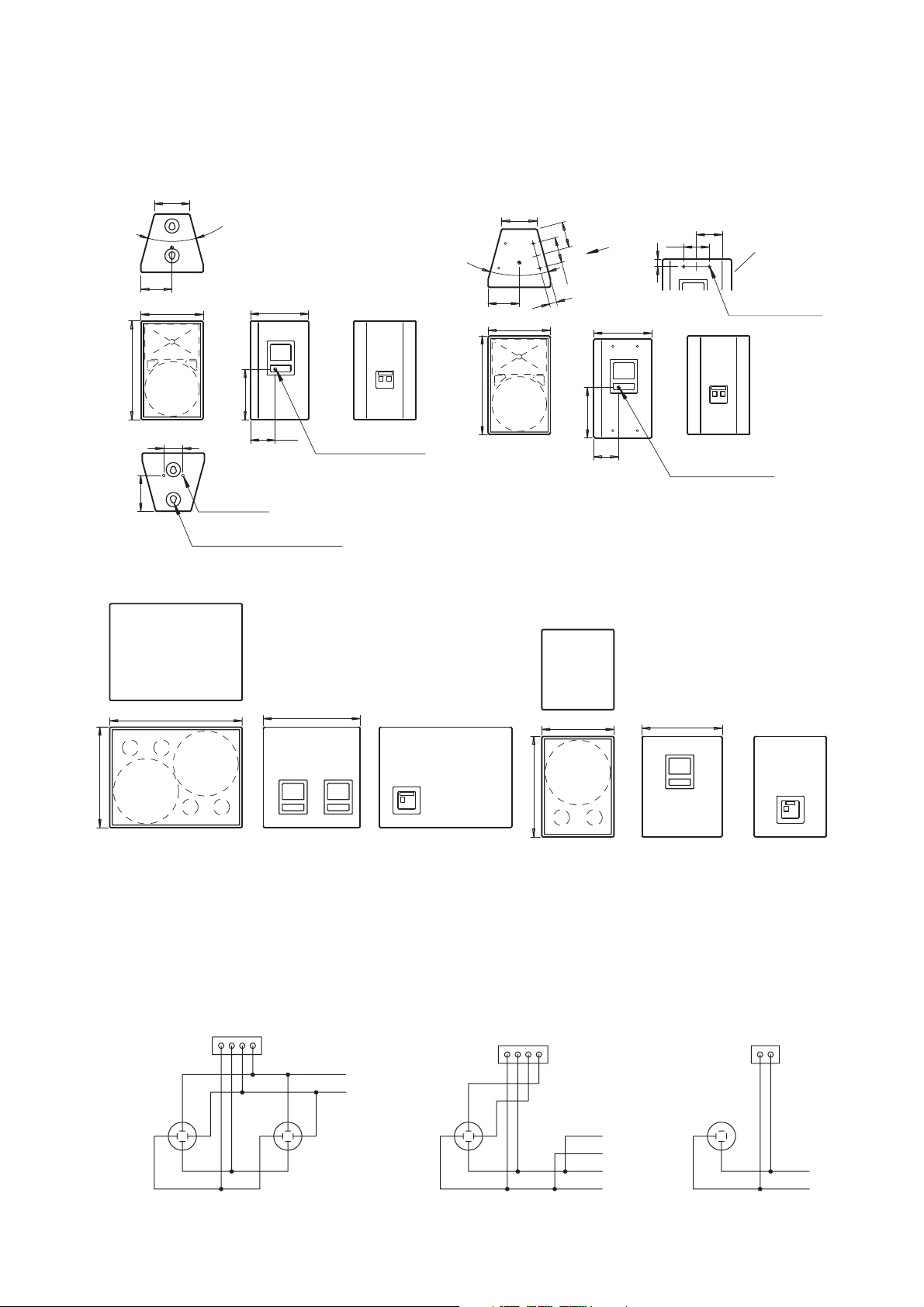
[SR-F09, SR-F09-V1, SR-F09-V2, SR-F09-V3]
[SR-L09] [SR-L05]
4
221
195
30°
390
619
364
315
155
120
224
221
3
0°
161
160
195
46
A
161
160
46
390
619
364
155
315
829
629
606
502
452
629
2-M8 Nut
Center of gravity
Flying fitting (4 places)
Center of gravity
16-W3/8'' Nut
The side as
viewed from
the direction
of arrow A
[SR-F09, SR-F09-V1]
[SR-F09-V2, SR-F09-V3]
[SR-L09] [SR-L05]
Unit: mm
5. WIRING DIAGRAMS
4. DIMENSIONAL DIAGRAMS
Screw terminal 4P
1+
2
1
-
2+
NL4MP NL4MP
1+
2
1
-
2+
Screw terminal 4P
(+)
-
)
(
1+
2
-
2+
NL4MP
1
-
(+)
-
)
(
(+)
(
-
)
(LEFT)
(RIGHT)
Screw terminal 2P
1+
2
1
-
2+
NL4MP
(+)
(-)
Page 5

5
7. CONNECTIONS
7.1. Combination with a Sub-woofer
7.2. Singular System of SR-F09, SR-F09-V1, SR-F09-V2 and SR-F09-V3
7.3. About the Power Amplifier to Connect
It is recommended that you use a power amplifier with output of over 400 W (per channel when an 8Ω load is
connected).
[SR-F09, SR-F09-V1, SR-F09-V2, SR-F09-V3] [SR-L09] [SR-L05]
• Pins of the Neutrik connector are connected as shown in the table below.
• The usable connector (on the cable end) for the NL4MPR connector is Neutrik's NL4FC.
Pin No. SR-F09, SR-F09-V1, SR-F09-V2, SR-F09-V3 SR-L09 SR-L05
1 + Speaker +
--
1
-
Speaker
-
--
2 +
-
Speaker + Speaker +
2
-
-
Speaker
-
Speaker
-
6. INPUT CONNECTORS
• The figures below show each speaker's input configuration. Because the connector is internally connected in
parallel to the screw terminal, you can use either of the two.
SR-F09, SR-F09-V1, SR-F09-V2, SR-F09-V3
DP-0206
Digital Processor
INPUT
MAIN OUT
BASS OUT
DP-0206
Digital Processor
INPUT
MAIN OUT
Power amplifier
SR-L09, SR-L05
SR-F09, SR-F09-V1, SR-F09-V2, SR-F09-V3
Power amplifier
Page 6

WARNING
6
8.2. SR-F09-V2 and SR-F09-V3
• A total of 16 3/8" nuts are
provided on the top, bottom and
side panels. Use more than three
of them for flying as shown on
the right.
8. FLYING
Be sure to refer flying construction work to the dealer from whom
the speaker was purchased.
8.1. SR-F09 and SR-F09-V1
Shown below are the general flying methods:
[Precautions]
• Two flying fittings are provided on each of the
top and bottom panels.
• Provide at least 2 suspension points at each
speaker.
• The maximum number of speakers that can
be suspended vertically is three.
Never suspend as illustrated below:
• Flying through only
one suspension point
on the top panel.
• Flying through handles.
• Vertical suspension of
more than 3 speakers.
• Flying with a single
looped wire
• Flying using the nuts
on the bottom surface
These speakers cannot be joined to each other.
Also, do not use carrying handles for flying.
Page 7

7
9. DIGITAL PROCESSOR SETTINGS
[Bi-amplifier drive for SR-F09+SR-L09/L05]
Channel
SR-L09
SR-F09 LOW
SR-F09 HIGH
Gain
−10.0
Polarity
(dB)
NORMAL
+5.0
0 NORMAL
INVERSE
[Bi-amplifier drive for SR-F09]
Channel
SR-F09 LOW
SR-F09 HIGH
Gain
−10.0
Polarity
(dB)
0 NORMAL
INVERSE
HPF/LPF
HPF (24dB)
LPF (24dB)
HPF (24dB)
LPF (24dB)
HPF (24dB)
HPF/LPF
HPF (12dB)
LPF (24dB)
HPF (24dB)
X-over Combination
LinkwitzRiley
LinkwitzRiley
LinkwitzRiley
LinkwitzRiley
LinkwitzRiley
X-over Combination
LinkwitzRiley
LinkwitzRiley
LinkwitzRiley
Freq. (Hz)
20
80
100
1.0k
1.0k
Freq. (Hz)
30
1.0k
1.0k
TYPETYPE
PEQ
PEQ
PEQ
PEQ
PEQ
High Shelving
TYPETYPE
PEQ
PEQ
PEQ
PEQ
High Shelving
Filter
Freq. (Hz) Gain (dB)
40
160
580
3.15k
11.8k
12.5k
Filter
Freq. (Hz) Gain (dB)
100
580
3.15k
11.8k
12.5k
+2.5
+5.0
−3.5
−4.0
+10.0
+3.5
+6.0
−3.5
−4.0
+10.0
+3.5
Q
4.318
1.414
2.079
3.633
2.371
Q
1.414
2.079
3.633
2.371
Delay
(msec)
0.667
0.292
0
Delay
(msec)
0.292
0
[Single-amplifier drive for SR-F09+SR-L09/L05]
Channel
SR-L09
SR-F09
Gain
Polarity
(dB)
INVERSE
+6.0
0 NORMAL
HPF/LPF
HPF (12dB)
X-over Combination
LinkwitzRiley
[Single-amplifier drive for SR-F09]
Channel
SR-F09
Gain
Polarity
(dB)
0 NORMAL
HPF/LPF
HPF (12dB)
X-over Combination
LinkwitzRiley
Filter
Freq. (Hz)
70
Freq. (Hz) Freq. (Hz)
70
TYPETYPE
LPF (12dB)
PEQ
PEQ
PEQ
PEQ
TYPETYPE
PEQ
PEQ
PEQ
PEQ
PEQ
Freq. (Hz) Gain (dB)
50
200
550
1.7k
16k
Filter
70
200
550
1.7k
16k
1.000
+3.0
−3.0
−3.0
+6.0
Gain (dB) Q
+8.0
+3.0
−3.0
−3.0
+6.0
1.414
2.997
2.997
2.997
1.414
1.414
2.997
2.997
2.997
Delay
(msec)
Q
0
0
Delay
(msec)
Page 8

8
10. SPEAKER STAND FOR SR-F09 AND SR-F09-V1
The speaker stand manufactured by Köning & Meyer GmbH (K & M) of Germany is made available for use
with TOA's SR-F09 and SR-F09-V1 speakers.
The speaker stand consists of a Stand and a Stand Bracket, which are sold separately.
In addition, separately prepare 2 speaker mounting screws to secure the bracket to the speaker.
Stand: Model 213
Bracket: Model 19580
Speaker mounting screw: M8 x 20
10.1. USAGE (Refer to Fig. 1.)
1. Loosen the tripod fixing screw and open the tripod
legs outward so that the stays become level.
2. Attach the stand bracket to the speaker using the
speaker mounting screws and plain washers. (Fig. 2).
3. Loosen the bracket fixing screw, then place the
speaker on the stand.
4. After setting the speaker's orientation, retighten the
bracket fixing screw.
5. Loosen the height fixing screw.
6. Loosen the handle fixing screw and raise the handle,
then retighten the handle screw.
7. While holding down the lock button, adjust the
speaker's height by turning the height adjustment
handle. (Clockwise rotation raises the speaker.)
Note: You cannot rotate the handle unless the lock button
is continuously pressed. To complete the height
adjustment, ensure that the shaft is locked when
the lock button is released. (This can be checked
by rotating the handle slightly.)
8. Retighten the height fixing screw.
9. Loosen the handle fixing screw and replace the
handle by tilting it up, then retighten the handle screw.
Leave the handle tilted up except when adjusting the
height.
10. After use, reverse the above procedures to put away
the stand.
(Fig. 1)
(Fig. 2)
SR-F09, SR-F09-V1
Stand bracket 19580
Bracket fixing screw
Height fixing screw
Tripod fixing screw
Speaker Stand 213
Lock botton
Handle fixing screw
Height adjustment handle
Height adjuster
Tripod leg
Stay
Stand bracket
Plain washer
Speaker mounting screw
(to be separately prepared)
Page 9

CAUTION
9
• Only use the stand on the flat, hard ground or floor surfaces.
• Avoid installing the stand in the passage where people could trip over
the tripod legs.
• When using the stand outdoors, avoid locations exposed to strong
winds.
• To minimize the chance of the stand toppling over, avoid extending
the stand too high.
• When the stand could fall down, be sure to secure it with guy wires or
other devices.
11. CHANGE FROM SINGLE- TO BI-AMPLIFIER DRIVE
The SR-F09, SR-F09-V1, SR-F09-V2, and SR-F09-V3 can be driven by bi-amplifiers if wiring of their internal
connectors is changed. When using these speakers in combination with the SR-L09, its internal wiring must
also be changed.
11.1. Changing Internal Wiring
11.1.1. SR-F09, SR-F09-V1, SR-F09-V2, and SR-F09-V3
1. Remove front grille fixing screws (4 places) to
remove the front grille.
2. Remove horn fixing screws (8 places) to remove
the horn.
Front grille
fixing screw
Front grille
Connector
3. Disconnect connectors inside an enclosure.
Connector
4. Connect a connector having a marker on it to a
similarly marked connector, and an unmarked
connector to an unmarked connector.
Marker
5. Replace the horn using screws.
6. Replace the front grille using front grille fixing
screws.
Horn removed.
Page 10

10
11.1.2. SR-L09
11.2. Input Connector Connections
Change each speaker's input connectors as follows. Also, attach the supplied marker (seal) to change the
indication.
1. Remove front grille fixing screws (12 places) to
remove the front grille.
2. Remove the woofer located on the right hand side
as viewed from the front by removing eight screws.
Front grille
fixing screw
Front grille
3. Disconnect connectors inside an enclosure.
Connector
4. Connect a connector having a marker on it to a
similarly-marked connector.
Marker
5. Replace the woofer using screws.
6. Replace the front grille using the front grille fixing
screws.
Connector
Woofer removed.
Seal supplied with SR-F09, SR-F09-V1, SR-F09-V2, and SR-F09-V3 Seal supplied with SR-L09
Page 11

11
• Pins of the Neutrik connector are connected as shown in the table below.
• Because the connector is internally connected in parallel to the screw terminal, you can use either of the
two.
11.3. Connection diagram
Pin No. SR-F09, SR-F09-V1, SR-F09-V2, SR-F09-V3 SR-L09
1 + LOW + Left* +
1
-
LOW
-
Left
2 + HIGH + Right +
2
-
HIGH
-
Right
-
* The "left" and the "right"
are the directions as
viewed from the front.
[SR-F09, SR-F09-V1, SR-F09-V2, SR-F09-V3] [SR-L09]
11.4. Connections
Screw terminal 4P
1+
2
1
-
2+
NL4MP NL4MP NL4MP
INPUT
1+
2
1
2+
DP-0206
Digital Processor
Screw terminal 4P
(+)
LOW
(-)
1+
2
1
-
(+)
HIGH
(-)
Power amplifier
-
2+
SR-F09, SR-F09-V1,
SR-F09-V2, SR-F09-V3
(+)
-
(
(+)
(
(LEFT)
)
(RIGHT)
-
)
HIGH
LOW
SR-L09
Digital Processor
INPUT
Digital Processor
INPUT
DP-0206
DP-0206
Power amplifier
Power amplifier
SR-F09, SR-F09-V1,
SR-F09-V2, SR-F09-V3
HIGH
LOW
SR-L05
SR-F09, SR-F09-V1,
SR-F09-V2, SR-F09-V3
HIGH
LOW
Page 12

12. SPECIFICATIONS
• Accessory
Input connector indication seal .................... 1
• Accessory
Input connector indication seal .................... 1
Note : The design and specifications are subject to change without notice for improvement.
Model No. SR-F09 SR-F09-V1 SR-F09-V2 SR-F09-V3
Enclosure Type Bass reflex type
Power Handling Capacity Continuous pink noise 200 W
Continuous program 600 W
Nominal Impedance 8Ω
Output Sound Pressure Level 100 dB (1 W, 1 m)
Frequency Characteristics 70 Hz – 20 kHz (when DP-0206 is used)
Crossover Frequency 1 kHz (passive network)
Speakers Woofer : Cone speaker with diameter of 30 cm
Tweeter : CD horn + compression driver
CD Horn Directional Angle
60° x 40° 90° x 60° 60° x 40° 90° x 60°
(horizontal by vertical)
Input Connector Neutrik NL4MP x 2 and 4P M5 screw terminal, Usable connector: NL4FC
Finish Enclosure : Plywood, black, paint
Front grille : Steel plate, black, acrylic paint
Dimensions 390 (w) x 619 (h) x 364 (d) mm
Weight 35 kg
Model No. SR-L09 SR-L05
Enclosure Type Bass reflex type
Power Handling Capacity Continuous pink noise 300 W Continuous pink noise 150 W
Continuous program 900 W Continuous program 450 W
Nominal Impedance 4Ω 8Ω
Output Sound Pressure Level 96 dB (1 W, 1 m) 93 dB (1 W, 1 m)
Frequency Characteristics 35 Hz – 1 kHz
Crossover Frequency 125 Hz (when DP-0206 is used)
Speakers 2 cone speakers with diameter of 38 cm Cone speaker with diameter of 38 cm
Input Connector Neutrik NL4MP x 2 and 4P M5 screw terminal, Usable connector: NL4FC
Finish Enclosure : Plywood, black, paint
Front grille : Steel plate, black, acrylic paint
Dimensions 829 (w) x 629 (h) x 606 (d) mm 452 (w) x 629 (h) x 502 (d) mm
Weight 67 kg 36 kg
133-01-409-1C
URL: http://www.toa.jp/
Traceability Information for Europe
Manufacturer:
TOA Corporation
7-2-1, Minatojima-Nakamachi, Chuo-ku, Kobe, Hyogo,
Japan
Authorized representative:
TOA Electronics Europe GmbH
Suederstrasse 282, 20537 Hamburg,
Germany
 Loading...