

Page 1
Please follow the instructions in this manual to obtain the optimum results from this unit.
We also recommend that you keep this manual handy for future reference.
SR-F3/SR-L3
SPEAKER SYSTEM
INSTRUCTION MANUAL
1.
SAFETY PRECAUTIONS
• Be sure to read the instructions in this section carefully
before use.
• Make sure to observe the instructions in this manual as
the conventions of safety symbols and messages
regarded as very important precautions are included.
• We also recommend you keep this instruction manual
handy for future reference.
Safety Symbol and Message Conventions
Safety symbols and messages described below are used
in this manual to prevent bodily injury and property
damage which could result from mishandling. Before
operating your product, read this manual first so you are
thoroughly aware of the potential safety hazards as well as
understand the safety symbols and messages.
WARNING Indicates a potentially hazardous
situation which, if mishandled, could result in death or
serious personal injury.
CAUTION Indicates a potentially hazardous
situation which, if mishandled, could result in moderate
or minor personal injury, and/or property damage.
When Installing the Unit
• Install the unit only in a location that can structurally
support the weight of the unit and the mounting bracket.
Doing otherwise may result in the speaker falling down
and causing personal injury and/or property damage.
• Flying Precautions (SR-F3 only)
Be sure to follow the instructions below. The suspension
wires or belts may be off or snap and the speaker may
fall, causing personal injuries.
· Check to confirm that the suspension wires and belts
are strong enough to withstand the speaker load.
· The connectors of the suspension wires and belts must
be securely linked with those of the speaker.
· All parts and components (such as enclosures, metal
pieces, and screws) must be free from any
deformation, crack, and corrosion.
WARNING
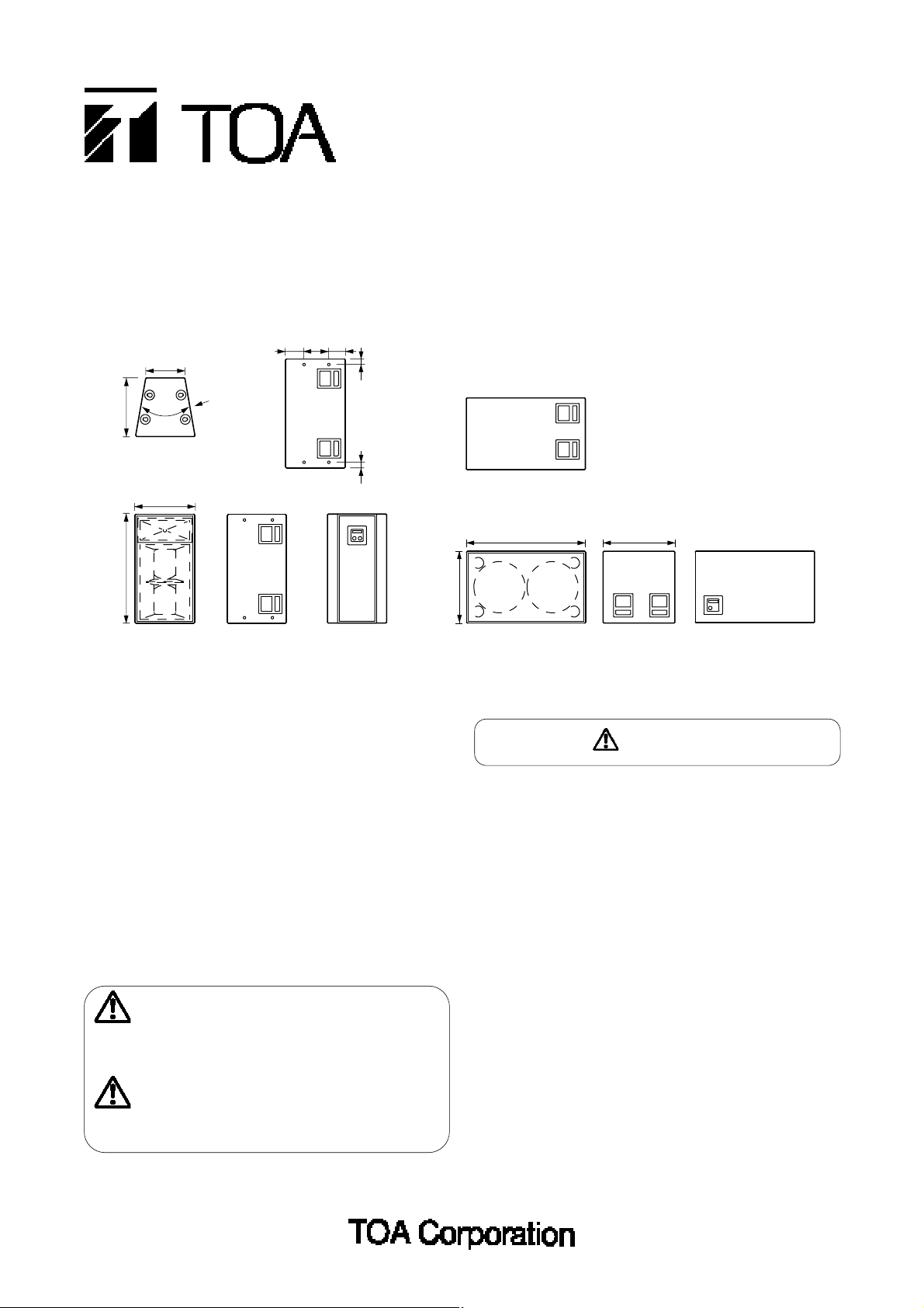
The side as viewed from
the direction of arrow A
[
SR-F3
]
[
SR-L3
]
Unit: mm
533
990
354
20°
542
A
167 149
5151
652
1082
652
Page 2
When Installing the Unit
• Install a speaker only in stable locations, and make
appropriate arrangements to prevent it from falling down
or rolling cross the floor. If it falls down or moves, this
may cause personal injury and/or property damage.
• When unpacking or moving a heavy speaker, be sure to
handle the unit with two or more persons. Falling or
dropping the speaker may cause personal injury and/or
property damage.
When the Unit is in Use
• Do not stand or sit on, nor hang down from the speaker
as this may cause it to fall down or drop, resulting in
personal injury and/or property damage.
• Do not operate the speaker for an extended period of
time with the sound distorting. This is an indication of a
malfunction, which in turn can cause heat to generate
and result in a fire.
2.
FEATURES
• The SR-F3 is a two-way full-range dual-amp-driven speaker system, and the SR-L3 is a sub-woofer system. Both
systems feature a high power handling capacity, high sound quality, and heavy-duty construction suited to both mobile
and permanent installation applications.
• Both speaker systems are designed to be used in conjunction with the dedicated controller.
• The SR-F3 houses a constant directivity (CD) horn that assures a uniform sound dispersion pattern of 60° horizontal by
30° vertical.
• The SR-F3 is equipped with a front-loaded horn with two 30 cm woofers.
• The SR-L3 employs two 46 cm woofers with a long voice coil.
• The SR-F3 has flying hardware (Aeroquip's ring/stud pan fitting) on both the top and the bottom, and an M16 nut on the
sides for attachment of an eye bolt.
• A light-weight, strong coniferous plywood enclosure is finished with extremely-durable epoxy paint.
• Input connectors are Nuetrik's NL4MPR and screw terminals. The SR-F3 is equipped with two Nuetrik connectors to
facilitate parallel connection.
• A woofer baffle is designed to permit easy woofer replacement without having to lay the speaker.
3.
INPUT CONNECTORS
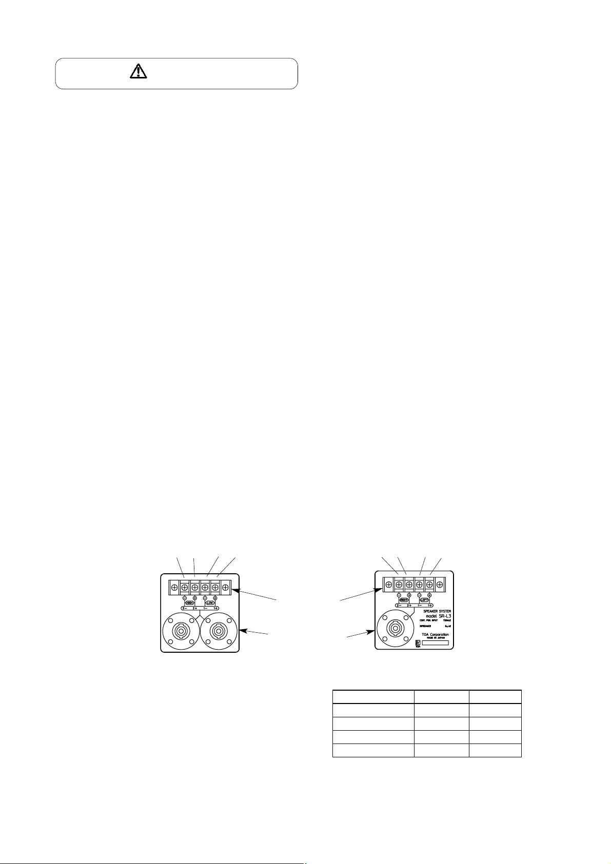
Each speaker's input connectors are as follows. Connections can be made from any connector because all connectors are
internally connected in parallel to each other.
Screw terminal
Neutrik NL4MPR
connector
HIGH LOW
-
+
Right
-
+
-
+
-
+
Left
[
SR-F3
]
[
SR-L3
]
• Contacts of the Neutrik connector are connected as shown
in the table at right.
• The usable connector (on the cable end) for the NL4MPR
connector is Neutrik's NL4FC.
Contact No. SR-F3 SR-L3
1 + LOW + Left +
1
-
LOW
-
Left
-
2 + HIGH +
Right
+
2
-
HIGH
-
Right
-
*
* The left and the right are the directions as
shown from the front.
CAUTION
Page 3
4.
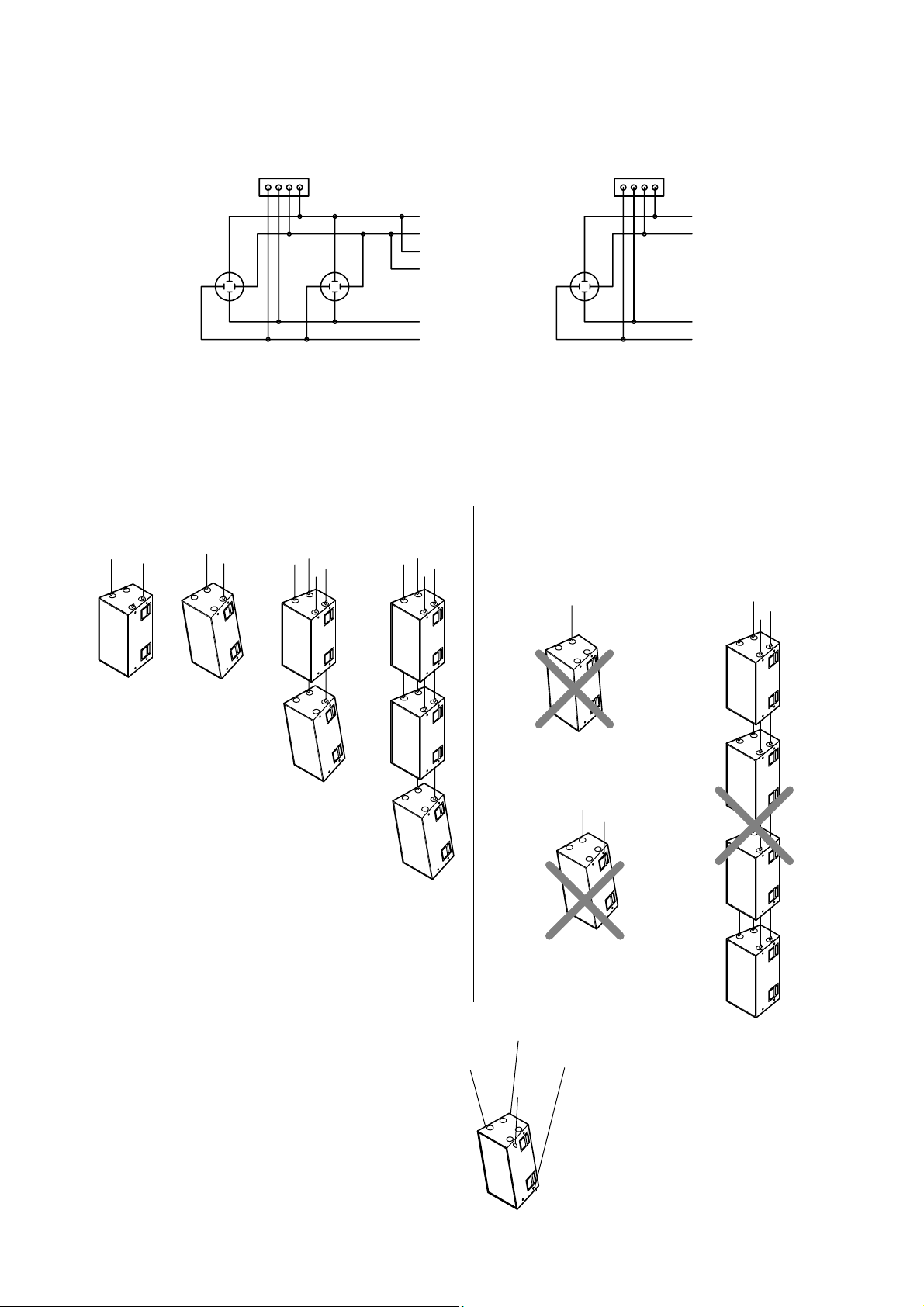
WIRING DIAGRAM
Screw terminal 4P Screw terminal 4P
[
SR-F3
]
[
SR-L3
]
5. FLYING
Be sure to consult an installer as to the following uses:
5.1 When using the flying hardware on the top or the bottom of the speaker.
Shown below are the general flying methods:
[Precautions]
• Provide at least two suspension points on each speaker.
• The maximum number of speakers that can be suspended
vertically is three.
Do not suspend as illustrated below:
• Flying through only one
suspension point.
• Flying through handles.
• Vertical suspension of
more than 3 speakers.
5.2 When using the nuts on the sides.
For an M16 nut provided on the sides, use an eye bolt with
the threaded section of 35-50 mm in length.
2–
2+
(+)
LOW
(+)
1+
1–
NL4MPR NL4MPR
2–
2+
1+
1–
(–)
(+)
(–)
LOW
HIGH
2–
NL4MPR
1+
2+
1–
(+)
LEFT
(–)(–)
(+)
RIGHT
(–)
Page 4

6.
CONNECTIONS
6.1 Combined system of the SR-F3 and SR-L3
7.
SPECIFICATIONS
6.2 System using only the SR-F3
Power amplifier
Mixer or pre-amplifier
Mixer or pre-amplifier
INPUT 2
INPUT 2
OUTPUT 3
OUTPUT 3
OUTPUT 2
OUTPUT 2
Dedicated
controller
OUTPUT 1
SR-F3
SR-F3
SR-L3
Power amplifier
Dedicated
controller
Note : The design and specifications are subject to change without notice for improvement.
SR-F3 SR-L3
Enclosure Type Front-loaded horn , sealed type Bass reflex type
Speakers Low frequency : 2 cone speakers with 2 cone speakers with diameter of 46 cm
diameter of 30 cm
High frequency : CD horn 60° (horizontal)
x 30° (vertical) + compression driver
Nominal Impedance Low frequency : 8 Ω 8 Ω x 2
High frequency : 16 Ω
Output Sound Pressure Low frequency : 105 dB (1 W/1 m) 98 dB ( 0.5 W + 0.5 W / 1 m )
Level High frequency : 111 dB (1 W/1 m)
Power Handling Capacity Low frequency : Continuous pink noise 240 W x 2 *
3
Continuous pink noise 240 W *1Continuous program 720 W x 2
Continuous program 720 W
High frequency :
Continuous pink noise 80 W *
2
Continuous program 240 W
Frequency Response 60 – 20,000 Hz (when using the dedicated 30 – 500 Hz
controller)
Crossover Frequency 800 Hz (when using the dedicated contrller) 125 Hz (when using the dedicated contrller)
Input Connector Neutrik NL4MPR x 2 Neutrik NL4MPR
and 4P M5 screw terminal and 4P M5 screw terminal
Enclosure Material Coniferous plywood (15 mm in thickness) Coniferous plywood (15 mm in thickness)
Finish Enclosure : Epoxy paint, dark gray Enclosure : Epoxy paint, dark gray
Punched Net : Acryl paint, black Punched Net : Acryl paint, black
Dimensions 542 (W) x 990 (H) x 533 (D) mm 1082 (W) x 652 (H) x 652 (D) mm
Weight Approximately 75 kg Approximately 86 kg
*1 24 hours pink noise input (50-1,000 Hz)
*2 24 hours pink noise input (800-20,000 Hz)
*3 24 hours pink noise input (40-1,000 Hz)
Printed in Japan
133-01-392-80
HIGH
HIGH
LOW
LOW
 Loading...