

Page 1
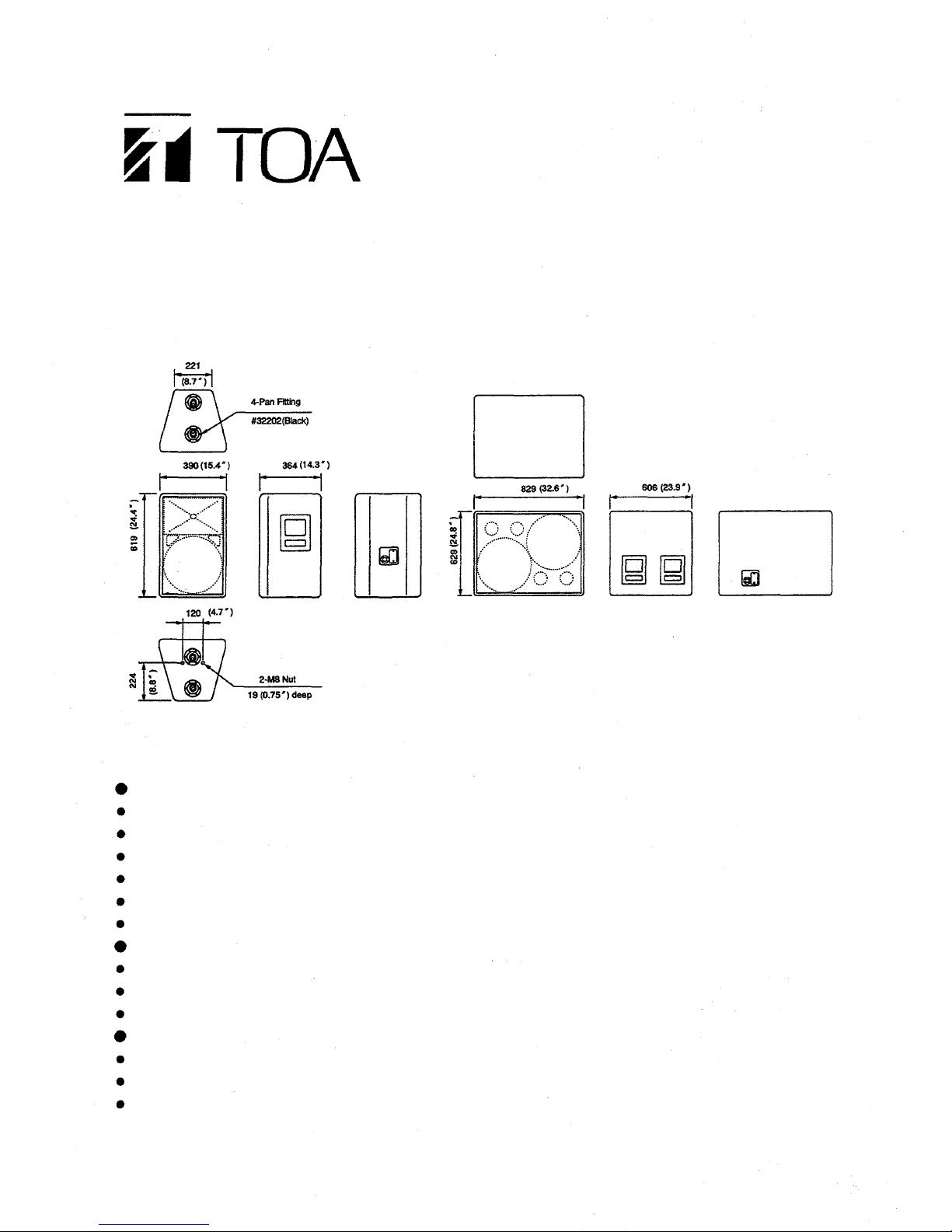
OPERATING INSTRUCTIONS
SR-F1B
SR-L1B
SPEAKER SYSTEM
SUPER WOOFER SYSTEM
Note: The SR-F1B comes with two nuts on the bottom side, which
are used only for mounting the SR-F1B to an optional
speaker stand. Never use these nuts for speaker suspension.
SR-F1B
Electronic-controlled system (bi-amplifier driven system) with the AC-F1 Electronic Control Unit.
High power capacity of 120 watts continuous pink noise for low frequency and 80 watts for high frequency.
High-efficiency 30 cm (12") woofer using a 20 cm (8") large magnet.
HFD-651 type high power driver with LE Series Constant Directivity(CD) Horn (60° horizontal by 40° vertical).
Fixing metals for suspension provided on top and bottom sides of the enclosu re.
Provided an angle of 15° at both sides of the enclosure to prevent mutual interference in high frequency range.
SR-L1B
Electronic-controlled system with the AC-L1 Electronic Control Unit.
High power capacity of 300 watts continuous pink noise.
Ultra-linear, high power 38cm (15") woofer.
General Features
Neutrik NL4MPR input connector.
APITON plywood enclosure with rugged FRP coating.
Removable punched metal front grill.
TOA Corporation
FEATURES
SR-F1B
SR-L1B
Page 2
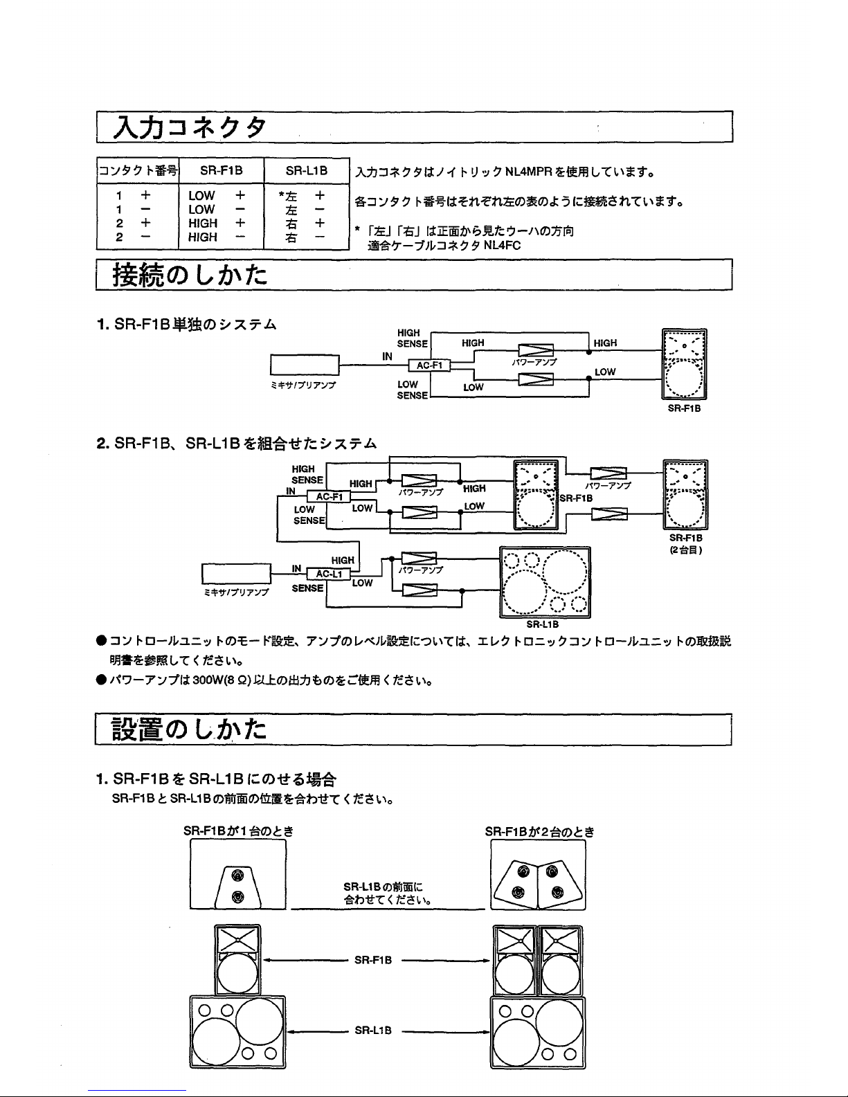
INPUT CONNECTOR
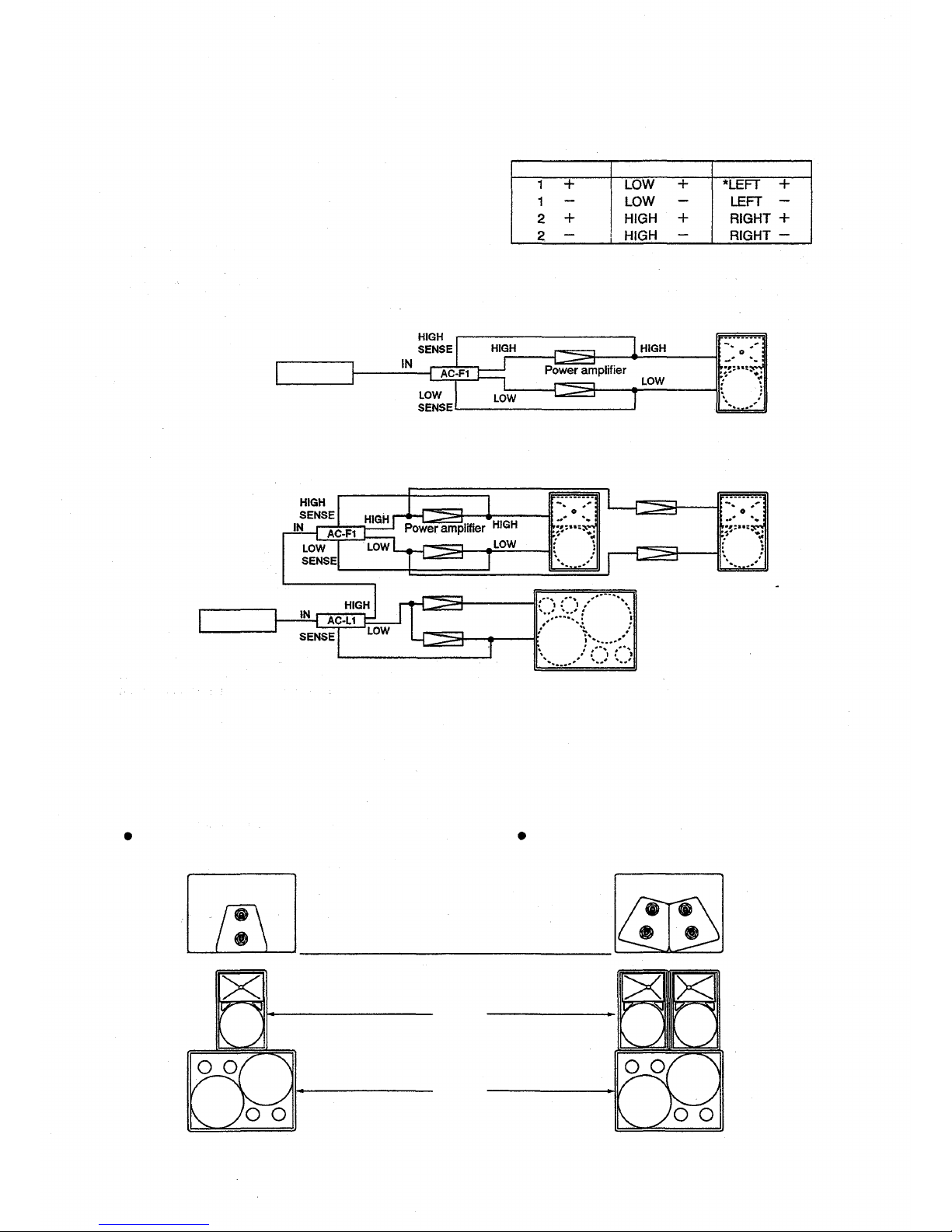
Each speaker employs the Neutrik NL4MPR connector for its input.
The table on the right shows the NL4MPR's contact arrangement.
The mated cable connector is the Neutrik NL4FC.
CONNECTION DIAGRAMS
Single System (SR-F1B)
* Woofer direction viewed from the front side.
Contact number
SR-F1B
SR-L1B
Combination System (SR-F1B and SR-L1B)
Mixer / preamplifier
Mixer/ preamplifier
Note: Refer t o the "Electronic control unit's operating instructions" for the mode setting of the electronic control unit and
the level setting of power amplifier.
INSTALLATION
Mounting the SR-F1B on the SR-L1B
When one SR-F1B is mounted on the SR-L1B
When two SR-F1Bs are mounted on the SR-L1B
Arrange so the front edges of the SR-F1B
and SR-L1B are aligned as shown in the figure.
SR-F1B
SR-L1B
SR-F1B
SR-F1B
SR-F1B
2
SB-L1B
Page 3
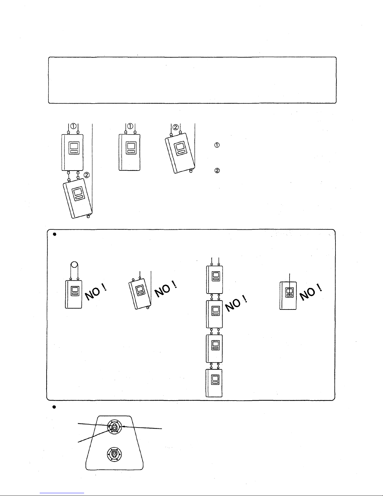
Suspending the SR-F1B
Note: The SR-L1B can not be suspended.
Caution
The SR-F1B weighs approximately 37 kg. Confirm that the structure of installation place, and suspending wires or belts
are heavy-duty enough to support the total weight of the load before suspension. Secure to lock the fixing metals of the
suspending wire or belt to the speaker. TOA takes no responsibility for any accidents or injuries resulting from the fall
of the SR-F1B due to incorrect installation.
• As for t he general suspending methods of t he SR-F1 B, refer to the figures below.
Be sure to use t w o suspending w ires or belts.
Fix them to the ceiling reinforcement
individually.
Even in case of oblique installation of the
speaker, be sure to use two suspending wires
or belts.
WARNING
Never suspend the speaker as shown in the figures below.
Never use a ringed one wire.
Never suspend the speaker
with a s ing le wire.
Never link more than three
speakers vertically.
Never suspend the speaker using
the speaker handles.
3
Fitting metal supplied with the SR-F1B
32202 Ring/Stud Pan Fitting (Aeroquip made)
To suspend the SR-F1B from its stud,
prepare the following applicable metal.
32326 Stud Fitting (Aeroquip made)
Suspending metal
Ring
Stud
Page 4
SPECIFICATIONS
Enclosure
Speaker
Low frequency
High frequency
Rated impedance
Sensitivity
Frequency response
Crossover frequency
Power
handling
Low frequency
High frequency
Input connector
Enclosure material
Weight
Dimensions
Finish
SR-F1B
SR-L1B
Bass reflex type
One 30cm(12 " ) dia. cone speaker
CD horn (60° horizontal by 40° Vertical)
plus compression driver
Low frequency : 8
High frequency : 16
Low frequency : 98dB(1W/1m)
High frequency : 110dB(1 W/1m)
70 Hz~20 kHz at AC-F1 's use
1 kHz at AC-F1's use
Continuous pink noise : 120 W RMS (
1 )
Continuous program : 360 W
Continuous pink noise : 80 W RMS ( 2)
Continuous program : 240 W
Two 38cm (15 ") dia. cone speakers
—
8 X2
96dB(0.5Wx2/1m)
35
Hz~1
kHz
125 Hz at AC-L1's use
Continuous pink noise : 150 W RMS x 2( 3)
Continuous program : 450 W RMS x 2
—
Neutric NL4MPR
Apiton plywood (Thickness : 18 mm or 0.71 * )
Approx. 37 kg (82 Ib.)
390 (W) X 619 (H) X 364 (D) mm
15.4(W) x 24.4(H) X 14.3(D) in.
Approx. 79 kg (174 Ib.)
829 (W) x 629 (H) x 606 (D) mm
32.6(W) x 24.8(H) x 23.9(D) in.
Enclosure : FRP coating in gray color
Front grille : Black (painted)
Specifications are subject to change without notice.
Standard Accessories: Operating instructions x 1
Mounting instructions x 1
( 1) Band Limited (50 to 1,000Hz) Pink Noise Signal (24 hours)
( 2) Band Limited (1,000 to 20,000Hz) Pink Noise Signal (24 hours)
( 3) Band Limited (40 to 1 ,000Hz) Pink Noise Signal (24 hours)
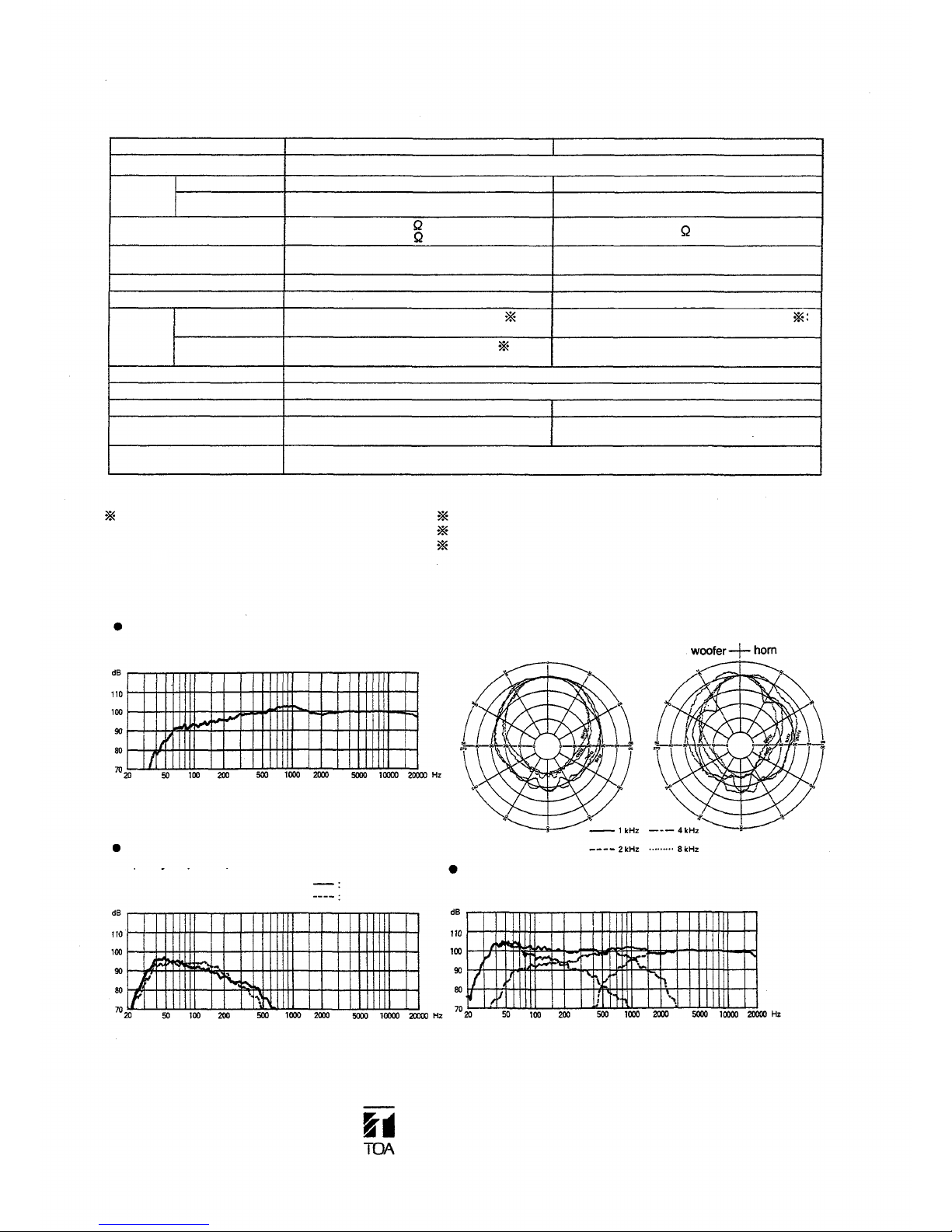
CHARACTERISTIC DIAGRAMS (1/3 octave pink noise)
SR-F1B (at AC-F1 electronic control unit's use)
Frequency response (1W/1m, at 300Hz)
Polar response (1W/4m)
Horizontal
Vertical
SR-L1B (at AC-L1 electronic control unit's use)
Frequency response (1W/1m, at 100Hz of crossover OUT)
General frequency response (1W/1m, at 300Hz of the SR-F1B)
SR-L1B+AC-L1, SR-F1B+AC-F1 AC-L1: Crossover OUT
Printed in Japan
133-01-381-60
TOA Corporation
AC-L1 mode
Crossover OUT
Crossover IN
Page 5
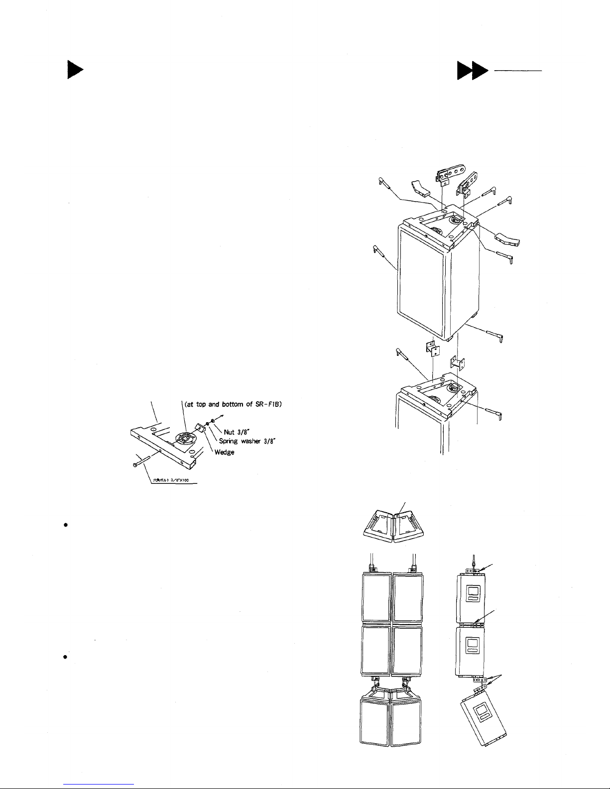
SR-F1B SPEAKER FLYING SYSTEM
This speaker flying hardware system is manufactured by ATM FLY-WARE™ (ATM GROUP, Inc.) of the United States for use
with TOA's SR-F1B speaker. The flying system enables various speaker array configurations to be constructed quickly and
safely without special components.
SYSTEM COMPOSITION
The flying system is comprised of five main components.
1 .[AMFS-SRF1-TH Truss Module] Allowable load 275 kg
The truss module attaches to both the top and bottom of the SR-F1B
speaker.
<Note> Speaker fixing screws are supplied with the truss module.
2 .[AMFS-1X2-30 Connecting Bar] Allowable load 278 kg
The connecting bar is used for horizontal speaker connection.
3 .[AMFS-1X2-SME Shackle Mount] Allowable load 225 kg
The shackle mount is used to set suspension points for vertical speaker
suspension.
(Multiple
rows
of
speakers
can be
suspended
at
different
tilt
angles.)
4.[AMFS-1X2-SB Stacking Bracket] Allowable load 194 kg
The stacking bracket is used to suspend multiple rows of speakers in a
straight vertical format without varying
array
tilt
angles.
5 . [2.5QRP Quick Release Pin] Allowable load 835 kg
The quick release pin has a lock function and is used to connect
individual parts.
MOUNTING TRUSS MODULE
Truss module
Pan fitting ring
Hexagon bolt 3/8" x 41/2"
Caution
Never use mounting
hardware other than
supplied.
WARNING
EXAMPLE OF USAGE
The following limitations must be observed even when the allowable load
requirement is met.
(1) A maximum of four speakers can be suspended per shackle mount
(AMFS-1X2-SME) or stacking bracket (AMFS-1X2-SB).
Example 1: A column of eight speakers configured two high and four wide
can be suspended from two AMFS-1X2-SME Shackle Mounts.
Example 2: A column of ten speakers configured two high and five wide
would require suspension from a minimum of three AMFS-1X2SME Shackle Mounts.
(2) A maximum of three rows of speakers using this flying hardware system
may be suspended in the vertical plane.
Confirm the following points before installation.
(1) Total actual load of each component must be lower than the allowable
load for that component.
(2) All quick release pins (2.5QRP) must be inserted into other components
to lock them securely.
(3) All components that relate to array suspension (i.e. enclosures, individual
components of the flying hardware system, clamps, connectors, and
suspension devices) must be free from any deformation, crack and
corrosion.
AMFS-1X2-SME
AMFS-1X2-SB
AMFS-1X2-SME
AMFS-1X2-30
AMFS-1X2-SME
AMFS-1X2-SME
2.5QRP AMFS-1x2-30
AMFS-SRF1-TH
2.5QRP
2.5QRP
2.5QRP
AMFS-1X2-30
2.5QRP
AMFS-SRFI-TH
AMFS-1X2-SB
2.5QRP
AMFS-SRFI-TH
AMFS-1X2-SB
2.5QRP
2.5QRP
Page 6

SR-F1B SPEAKER STAND
This speaker st an d is m anufactured by König&Meyer Gm bH(K&M) of Germany for use with TOA's SR-F1B speaker.
The speaker stand consists of two main sections:
Stand: Model 213
Bracket: Model 19582
USAGE
(Refer
to
Fig.
1.)
Extending the Stand Legs.
1 . Loosen the tripod clamp screw and extend the tripod legs by
sliding the clamp ring down the length of the stand until the leg
stays are horizontal, then retighten the screw.
Mounting the Speaker.
2 . Attach the stand bracket to the base of the speaker using the
supplied mounting screws and washers. (Fig. 2).
3 . After ensuring that the bracket clamp screw is loose and not
protruding into the interior of the bracket, carefully place the
speaker on the stand by sliding the bracket over the end of the
stand.
4 . After positioning the speaker, tighten the bracket clamp screw.
Adjusting Stand Height.
5 . Loosen the height lock screw.
6 . Loosen the handle clamp screw, then fold out the crank handle
and retighten the screw.
7 . While holding d own the lock button, adjust the speaker's height by
turning the crank handle. (Clockwise rotation raises the speaker.)
The handle cannot be turned without holding down the lock button.
After adjustment is completed, release the lock button and make sure
that the shaft is securely locked. (This can be checked by rotating the
handle slightly.)
8 . Retighten the height lock screw .
9 . Loosen the handle clamp screw, flip the handle back into its
foldaway position and retighten the handle clamp screw. Be sure
the handle is always folded up except when adjusting the height.
Removal After Use
10. After use, lower and detach the speaker, then collapse the stand
in the reverse order of the above procedure.
Speaker Mounting Screw Storage
After the stand bracket is detached from the speaker, the speaker
mounting screws can be inserted into the threaded holes of the stand
bracket for storage. (Fig. 3).
PRECAUTIONS
Only use the stand on flat, hard ground or floor surfaces.
Avoid installing the stand near narrow passages where passers by might trip over the tripod legs.
When using the stand outdoors, take care to avoid exposure to strong winds.
To reduce the chance of the stand toppling over, avoid extending the stand too high.
When there is potential for instability and the danger of a fall, be sure to secure the stand with guy wires or other
devices.
<Fig. 2 >
<Fig. 1>
Speaker mounting scre w
Plain washer
Threaded hole
<Fig. 3>
Plain washer-
Speaker mounting screw
Stand bracket
clamp screw
Height lock screw
Tripod clamp screw
Lock button
Handle clamp screw
Crank handle
Height adjuster
Tripod leg
Stay
Page 7

SR-F1B
Page 8

SR-F1B
Page 9

TOA
SR-F1B
SR-L1B
Page 10
2
Page 11

3
Page 12

133-01-380-50
Page 13

SAFETY PRECAUTIONS
Follow this instruction manual to obtain the optimum
results before use.
We also recommend you keep this instruction manual
handy for future reference.
Note that this manual may include safety precautions not
applied to your products.
INSTRUCTION MANUAL
Symbols
Symbol of
caution actions
Caution
Symbol of
prohibited actions
Prohibition
WARNING
Indicates a potentially hazardous situation which, if mishandled, could
result in death or serious personal injury.
Avoi d installing or mounting the unit in unstable locations, such as on a rickety
table or a slanted surface. Doing so may result in the unit falling down and
causing personal injury and/or property damage.
Prohibition
Install th e unit only in a location that can structurally support the weight of the
unit and the mounting bracket. Doing otherwise may result in the unit falling
down and causing personal injury and/or property damage.
Caution
CAUTION
Indicates a potentially hazardous situation which, if mishandled, could
result in moderate or minor personal injury, and/or property damage.
Install th e unit only in stable locations, and make appropriate arrangements to
prevent it from falling down or rolling cross the floor. If it falls down or moves,
this may cause personal injury and/or property damage.
Caution
When unpacking o r moving a heavy unit, be sure to handle the unit with two or
more persons. Falling or dropping the unit may cause personal injury and/or
property damage.
Caution
Do not place heavy objects on the unit as this may cause it to fall or break which
may result in personal injury and/or property damage. In addition, the object
itself may fall off and cause injury and/or damage.
Do not stand or sit on, nor hang down from the unit as this may cause it to fall
down or drop, resulting in personal injury and/or property damage.
Do not operate the unit for an extended period of time with the sound distorting.
This is an indication of a malfunction, which in turn can cause heat to generate
and result in a fire.
Avoid placing t he unit in a doorway or other high traffic area as people may trip
on the equipment and cords, or be injured by falling objects.
TOA Corporation
Prohibition
Prohibition
Prohibition
Prohibition
133-21-296-50
Page 14

TOA
* Please see the reverse side for English safety instructions.
 Loading...