

Page 1
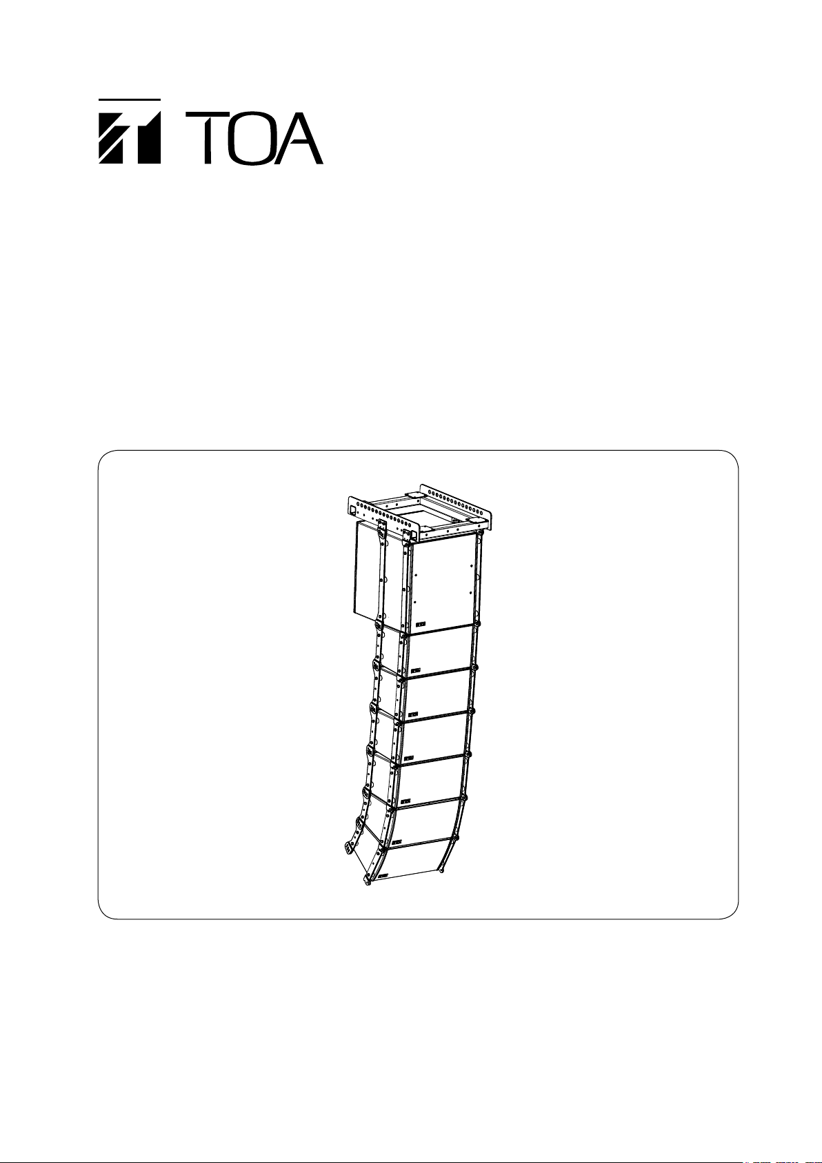
OPERATING INSTRUCTIONS
LINE ARRAY SPEAKERS
(SPLASH-PROOF TYPE)
RIGGING FRAME
(SPLASH-PROOF TYPE)
SR-C8LWP
SR-C8SWP
SR-C15BWP
SR-RF8WP
Thank you for purchasing TOA Line Array Speaker.
Please carefully follow the instructions in this manual to ensure long, trouble-free use of your equipment.
Page 2

2
TABLE OF CONTENTS
1. SAFETY PRECAUTIONS ............................................................................................... 3
2. GENERAL DESCRIPTION ............................................................................................. 5
3. FEATURES .......................................................................................................................... 5
4. INSTALLATION PRECAUTIONS ................................................................................. 5
5. DIMENSIONAL DIAGRAMS
5.1. Speaker Systems
5.1.1. SR-C8LWP Line array speaker ............................................................................. 6
5.1.2. SR-C8SWP Line array speaker ............................................................................. 6
5.2. Sub-Woofer Speaker System
5.2.1. SR-C15BWP Line array speaker ........................................................................... 7
5.3. Frame
5.3.1. SR-RF8WP Rigging frame .................................................................................... 7
6. BI-AMPLIFIER AND SINGLE-AMPLIFIER OPERATIONS
6.1. Bi-Amplifier Operation ...................................................................................................... 8
6.2. Single-Amplifier Operation ............................................................................................... 8
7. SWITCHING TO SINGLE-AMPLIFIER OPERATION MODE .............................. 9
8. DIGITAL PROCESSOR SETTINGS
8.1. SR-C8LWP and SR-C8SWP Systems ........................................................................... 10
8.2. Combined SR-C8LWP or SR-C8SWP and SR-C15BWP Systems ............................... 11
9. FLYING SYSTEMS USING THE SR-RF8WP RIGGING FRAME
9.1. Flying System Outline .................................................................................................... 12
9.2. Assembling the SR-RF8WP Rigging Frame .................................................................. 15
9.3. Connecting the Rigging Frame to the Speaker .............................................................. 16
9.4. Connection Between Speakers ...................................................................................... 17
9.5. About the Flying Installations ......................................................................................... 18
10. SPECIFICATIONS
10.1. SR-C8LWP and SR-C8SWP ........................................................................................ 19
10.2. SR-C15BWP ................................................................................................................19
10.3. SR-RF8WP ................................................................................................................... 20
Page 3
3
1. SAFETY PRECAUTIONS
When Installing the Unit
• Avoid installing or mounting the unit in unstable
locations, such as on a rickety table or a slanted
surface. Doing so may result in the unit falling
down and causing personal injury and/or property
damage.
• Refer all installation work to the dealer from whom
the speaker was purchased. Installation for flying
requires extensive technical knowledge and
experience. The speaker may fall off if incorrectly
installed, resulting in possible personal injury.
• Flying precautions.
Be sure to follow the instructions below. Otherwise,
the suspension wires or belts may be off or snap
and the speaker may fall off, causing personal
injury.
· Check to confirm that the suspension wires and
belts are strong enough to withstand the speaker
load.
· The connectors of the suspension wires and belts
must be securely linked with those of the
speaker.
· All parts and components (such as enclosures,
metal pieces, and screws) must be free from any
deformation, crack, and corrosion.
· Be sure to use screws supplied with the optional
flying hardware when installing the speaker using
such hardware.
• Install the unit only in a location that can
structurally support the weight of the unit and the
mounting bracket. Doing otherwise may result in
the unit falling down and causing personal injury
and/or property damage.
• Owing to the unit's size and weight, be sure that at
least two persons are available to install the unit.
Failure to do so could result in personal injury.
WARNING
Indicates a potentially hazardous situation which, if mishandled, could
result in death or serious personal injury.
Indicates a potentially hazardous situation which, if mishandled, could
result in moderate or minor injury, and/or property damage.
WARNING
CAUTION
• Be sure to read this safety instructions in this section carefully in prior to use.
• Be sure to follow all the precautionary instructions in this section, which contain important warnings and/or
cautions regarding safety.
• After reading, keep this manual handy for future reference.
Safety Symbol and Message Conventions
Safety symbols and messages described below are used in this manual to prevent bodily injury and property
damage which could result from mishandling. Before operating your product, read this manual first and
understand the safety symbols and messages so you are thoroughly aware of the potential safety hazards.
Page 4

4
When Installing the Unit
• When unpacking or moving the unit, be sure to
handle it with two or more persons. Falling or
dropping the unit may cause personal injury and/or
property damage.
• Avoid touching the unit's sharp metal edge to
prevent injury.
When the Unit is in Use
• Do not operate the unit for an extended period of
time with the sound distorting. Doing so may cause
the connected speakers to heat, resulting in a fire.
• Have the unit checked periodically by the shop
from where it was purchased. Failure to do so may
result in corrosion or damage to the speaker or the
unit that could cause it to fall, possibly causing
personal injury.
CAUTION
Page 5

5
2. GENERAL DESCRIPTION
3. FEATURES
4. INSTALLATION PRECAUTIONS
TOA's lineup of line array speakers employs TOA's unique wave front control technology to create a sound
field that offers clear reproduction and uniform sound dispersion. This lineup includes versions offering either
5 degrees or 15 degrees of angled vertical directivity, as well as sub-woofer configured types. The use of
optional support brackets allows the line array speakers to be used in many applications as permanent sound
system installations.
• TOA's unique wave front control technology creates a uniform sound distribution field with interference-free
high frequency output, realizing high-clarity acoustic characteristics and long sound transmission
capabilities.
• The SR-C8LWP is a two-way speaker mounting a high-power 20 cm woofer and two compression drivers,
and featuring a 5 degree angle of vertical directivity and 110 degrees of horizontal. It is ideal for long
distance applications and can be powered by either one or two amplifiers.
• The SR-C8SWP is a two-way speaker mounting a high-power 20 cm woofer and two compression drivers,
and featuring a 15 degree angle of vertical directivity and 110 degrees of horizontal. It is ideal for shorter
distance applications and can be powered by either one or two amplifiers.
• By combining the long-distance SR-8LWP and short-distance SR-8SWP, a line array speaker system can be
built to support a variety of applications.
• The SR-C15BWP sub-woofer employs a large-diameter 38 cm woofer with high power handling capabilities,
and is designed to be used in conjunction with the SR-C8LWP or SR-C8SWP line array speakers.
• The line array speakers are designed to allow easy rear access for maintenance work.
• Overlap angles between individual speakers can be set in 1 degree units between 0 and 5 degrees when
constructing the line array speaker, making it possible to flexibly control speaker directivity.
• The line array speaker can be suspended with the additional use of the SR-RF8WP Rigging Frame.
The WP series is a splash-proof speaker, however please be sure to install it under a roof or eaves or in other
locations where the speaker is not directly exposed to rain or snow. Also, avoid installing the speaker in such
high-temperature and high-humidity locations as swimming pool facilities. Failure to follow these instructions
could lead to equipment malfunctions.
Page 6
6
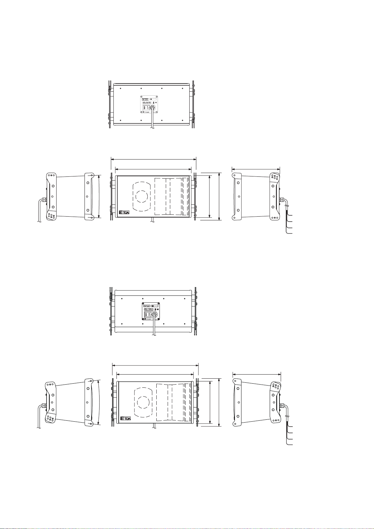
5. DIMENSIONAL DIAGRAMS
5.1.1. SR-C8LWP Line array speaker
5.1.2. SR-C8SWP Line array speaker
5.1. Speaker Systems
(Rear view)
526.6 [20.73"]
470 [18.5"]
5°
(Front view)(Left side view)
296 [11.65"]
293 [11.54"]
259.6 [10.22"]
(Right side view)
Unit: mm
Green LOW
Black LOW (-)
Red HIGH (+)
White HIGH (
(+
)
-
)
(Rear view)
526.6 [20.73"]
15°
(Front view)(Left side view)
470 [18.5"]
294 [11.57"]
293 [11.53"]
258.8 [10.19"]
(Right side view)
Unit: mm
Green LOW
Black LOW (-)
Red HIGH (+)
White HIGH (
(+
)
-
)
Page 7

7
5.3.1. SR-RF8WP Rigging frame
5.2.1. SR-C15BWP Line array speaker
5.3. Frame
5.2. Sub-Woofer Speaker System
(Rear view)
526.6 [20.73"]
470 [18.5"]
(Front view)(Left side view)
540 [21.26"]
594.8 [23.42"]
550 [21.65"]
(Right side view)
Unit: mm
Green Input (+)
Black Input (
Red NC
White NC
-
)
25 [0.98"]
93 [3.66"]
36 [1.42"]
15-ø20 [ø0.79"]
(Left side view)
14 [0.55"]
510 [20.08"]
(Top view)
6 [0.24"] 498 [19.61"]
6.4 [0.25"]
(Front view)
167 [6.58"]
105 [4.13"]
690 [27.17"]
4.5 [0.18"]
50 [1.97"]
Unit: mm
85 [3.35"]
155.5 [6.12"]
(Right side view)
(Bottom view)
50 [1.97"]
Page 8

8
6. BI-AMPLIFIER AND SINGLE-AMPLIFIER OPERATIONS
The SR-C8 series speakers are supplied from the factory set up for bi-amplifier operation. However, this
default specification can be switched to single-amplifier operation mode by simply changing the position of an
internal connector. (Refer to page 9. "Switching to Single-Amplifier Operation Mode.")
6.1. Bi-Amplifier Operation
6.1.1. System diagram
6.2. Single-Amplifier Operation
6.2.1. System diagram
6.1.2. Internal wiring diagram
6.2.2. Internal wiring diagram
Mixer/
preamplifier
-
-
Green
Black
Red
White
LOW +
LOW
HIGH +
HIGH
Digital
processor
LOW
HIGH
Power amplifier
Speaker cable
LOW
HIGH
SR-C8LWP/C8SWP
Woofer
Tweeter
Woofer
Tweeter
Mixer/
preamplifier
-
Green
Black
Red
White
INPUT +
INPUT
N.C.
N.C.
Digital
processor
Speaker cable
Power
amplifier
LOW
Passive
network
HIGH
SR-C8LWP/C8SWP
Passive
network
Woofer
Tweeter
Woofer
Tweeter
Page 9

9
7. SWITCHING TO SINGLE-AMPLIFIER OPERATION MODE
To switch the speaker's bi-amplifier operation mode to single-amplifier operation, remove the speaker's rear
input panel and change the speaker's internal wiring.
Switching Power Modes
Step 1. Remove the four screws securing the input terminal panel and pull out the panel.
Step 2. Pull out a short length of the wiring connected to the back side of the input panel.
Step 3. Disconnect and switch the two pairs of connected connectors so that the two marked and unmarked
connector halves match up.
Step 4. Reinstall the input terminal panel using the four removed screws.
Step 5. Attach the supplied seals to the input terminal panel to change the indication.
5
Changing input terminal panel indication
Input indication seal
for single-amplifier
operation (accessory)
Rating seal for
single-amplifier
operation (accessory)
Panel mounting screws
1, 4
Input terminal panel
2
3
Switching connectors
Mark
Page 10

10
8. DIGITAL PROCESSOR SETTINGS
Set the digital processor's parameters as follows:
8.1. SR-C8LWP and SR-C8SWP Systems
8.1.1. Bi-amplifier operation
8.1.2. Single-amplifier operation
Channel
Pre-stage Filter
SR-C8
LOW
SR-C8
HIGH
The “Gain” indications are merely provided as guidelines and may need be adjusted depending on the system
configuration.
Gain
(dB)
0
–9.0
Polarity
Normal
(Positive)
Normal
(Positive)
TYPE Freq. (Hz)
PEQ 1.6k –4.0 1.414
LPF (12 dB) 2.0k 0.707
HPF (12 dB) 60 1.000
PEQ 800 –5.0 3.450
HPF (12 dB) 2.0k 0.707
PEQ 1.45k 6.0 4.318
PEQ 2.9k 10.0 2.997
High Shelving 10k 7.0
All Pass 4.5k 2.016
All Pass 7.6k 2.016
All Pass 11.5k 2.215
All Pass 12.0k 2.016
All Pass 14.0k 1.512
All Pass 17.0k 4.938
Filter
Gain (dB) Q
(msec)
Delay
0.667
0
Channel
SR-C8
Gain
(dB)
0
Polarity
Normal
(Positive)
Filter
TYPE Freq. (Hz)
HPF (12 dB) 60 1.000
PEQ 280 3.5 4.318
PEQ 800 2.0 3.450
PEQ 2.5k
PEQ 2.65k 5.0 2.145
PEQ 5.3k 2.5 1.204
PEQ 9.0k 6.0 1.707
Gain (dB) Q
11. 5
1.044
Delay
(msec)
Page 11

11
8.2. Combined SR-C8LWP or SR-C8SWP and R-C15BWP Systems
8.2.1. Bi-amplifier operation
8.2.2. Single-amplifier operation
Channel
Pre-stage Filter
SR-C8
LOW
SR-C8
HIGH
“Gains” are merely given as a guideline and may need be adjusted depending on the system configuration.
Gain
(dB)
6.0
0
9.0
Polarity
Normal
(Positive)
Normal
(Positive)
Normal
(Positive)
TYPE Freq. (Hz)
PEQ 1.6k 4.0 1.414
HPF (12 dB) 35 2.053
LPF (6 dB) 50
LPF (12 dB) 100 1.432
PEQ 60 3.0 2.648
LPF (12 dB) 2.0k 0.707
HPF (12 dB) 100
PEQ 800 5.0 3.450
HPF (12 dB) 2.0k 0.707
PEQ 1.45k 6.0 4.318
PEQ 2.9k 10.0 2.997
High Shelving 10k 7.0
All Pass 4.5k 2.016
All Pass 7.6k 2.016
All Pass 11.5k 2.215
All Pass 12.0k 2.016
All Pass 14.0k 1.512
All Pass 17.0k 4.938
Filter
Gain (dB) Q
1.000
Delay
(msec)
1.896SR-C15B
0.667
0
Channel
SR-C15B 6.0
SR-C8 0
The “Gain” indications are merely provided as guidelines and may need be adjusted depending on the system
configuration.
Gain
(dB)
Polarity
Normal
(Positive)
Normal
(Positive)
TYPE Freq. (Hz)
HPF (12 dB) 35 2.053
LPF (6 dB) 50
LPF (12 dB) 100 1.432
PEQ 60 3.0 2.648
HPF (12 dB) 100
PEQ 280 3.5 4.318
PEQ 800 2.0 3.450
PEQ 2.5k 11.5 1.044
PEQ 2.65k 5.0 2.145
PEQ 5.3k 2.5 1.204
PEQ 9.0k 1.7076.0
Filter
Gain (dB) Q
Delay
(msec)
1.229
1.000
0
Page 12

12
9. FLYING SYSTEMS USING THE SR-RF8WP RIGGING FRAME
9.1. Flying System Outline
Use the SR-RF8WP Rigging Frame for flying applications. Up to twelve line array speakers can be
simultaneously connected per frame, however the SR-C15BWP is calculated as two units.
Adjust the vertical directivity angle according to the installation environment. For applications that specify longdistance sound transmission, link the long-distance SR-C8LWP speakers together.
Shown below is a basic flying system.
The line array speaker's vertical directivity angle is 5 degrees for the SR-C8LWP and 15 degrees for the SRC8SWP.
[SR-C8LWP] [SR-C8SWP]
Rigging frame
SR-C15BWP
SR-C8LWP
SR-C8SWP
5 degrees
15 degrees
Page 13

13
Notes
• The speaker's splash-proof capabilities meet IPX4 requirements. However, always make sure that the
speaker is installed in locations (such as under a roof or eaves, etc.) not directly exposed to rain or
snow.
• Be sure to install the speaker so that its air hole is positioned downward. In this case, the brand mark
should be situated on the lower left corner of the speaker.
• Install each speaker so that the downward angle formed by its top panel is between 0 and 50 degrees.
Ventilation slot Ventilation slot
Horizontal:
0 degree
50 degrees
Page 14

14
This flying system consists of four SR-C8LWP units, two SR-C8SWP units and one SR-C15BWP unit.
To enhance long-distance sound transmission capabilities, the four SR-C8LWPs are linked together at overlap
angles of four, two and one degree. As a result of this, the system's overall vertical directivity angle is 43
degrees.
Overlap angles can be set depending on how the speakers are linked together.
The horizontal directivity angle is 110 degrees.
As can be seen from the above figure, the overlap angle is equal to the rear opening angle between speakers.
Example: To adjust the sound radiation overlap angle to five degrees, set the rear opening angle between the
speakers to five degrees.
If the speakers are linked flat without no space between them, there will be no sound radiation
overlap. For overlap angle settings, refer to "Linkage Between Speakers" on page 17.
SR-C15BWP
4-degree speaker opening angle
2-degree speaker opening angle
1-degree speaker opening angle
SR-C8LWP
SR-C8SWP
SR-C8SWP
15 degrees
SR-C8LWP
SR-C8LWP
Overlap angle
Overlap angle
SR-C8LWP
15 degrees
Overlap angle
4 degrees
2 degrees
1 degree
5 degrees
5 degrees
5 degrees
43 degrees
Page 15

15
9.2. Assembling the SR-RF8WP Rigging Frame
Assemble the rigging frame referring to the figure below.
Ensure that fixing plates are correctly secured using two bolts (including plain and spring washers) supplied
with the rigging frame for each plate.
Since each fixing plate has its own installation position and orientation, refer to the figure for correct assembly.
Be sure that the forward mounting holes are always used in flying applications.
[Assembled frame]
Fixing plate
[Rear B]
Seal
Rear B
Rear Front
Rigging frame
SR-RF8WP
R
ear B
r
Fro
Seal
Front B
FrontRear
Fixing plate
[Rear A]
Seal
REAR
RearFront
Seal
FrontRear
FrontRear
ntRea
Seal
Rear A
Front Rear
Seal
Front A
RearFront
Fixing plate
[Front A]
FRONT
Fro
Rear
nt B
Front
* Mount each plate in compliance with
Fixing plate
the indication on each corresponding seal.
[Front B]
REAR
ear
R
nt
o
Fr
Rear A
RearFront
Rear
A
t
ont
Fron
Fr
FRONT
Page 16

16
9.3. Connecting the Rigging Frame to the Speaker
Connect the rigging frame to the speaker referring to the figures below.
Confirm the positioning of the horn (SR-C8LWP and SR-C8SWP only), then correctly mount the rigging frame
to the speaker by tightening the supplied nuts and bolts from both left and right sides.
When suspending the SR-C15BWP sub-woofer, be sure to mount it in the uppermost position (i.e.
immediately below the rigging frame).
[Speaker system assembly] [Sub-woofer system assembly]
Connection plate
Connection plate
Connection plate
Connection plate
Page 17

17
9.4. Connection Between Speakers
Inter-connect speaker sections referring to the figures below.
Ensure that both speakers are securely connected by tightening the supplied nuts and bolts from both left and
right sides.
Since connection holes for setting the overlap angle are provided at the back of the speaker, assemble using
the connection holes matching the required overlap angle. The overlap angle can be set within the range of 0
to 5 degrees in 1 degree units.
Front
Left side connection holes
for overlap angle settings
Right side connection holes
for overlap angle settings
Left side connection
holes for overlap angle settings
Overlap angle
0 degree
1 degree
2 degrees
5 degrees
4 degrees
3 degrees
Right hand side connection
holes for overlap angle settings
3 degrees
4 degrees
5 degrees
2 degrees
1 degree
0 degree
Page 18

18
9.5. About the Flying Installations
• Use at least two points on both the left and right sides to suspend
the system vertically.
• Use the suspension points that allow the system to be set for a
desired downward angle. The downward angle increases as the
suspension points are moved rearward.
• Add an anti-swing guy wire as required. However, take care that
the speaker system's weight is not applied to the wire.
Cautions
• Suspension wires and shackles are not supplied with the speaker. Separately prepare and use those
which are strong enough to suspend the speaker system. Further, ensure that the ceiling structure from
which the speaker system is suspended is also robust and capable of supporting the system's total
weight.
• A total of up to 12 line array speakers can be connected per rigging frame. However, the SR-C15BWP is
calculated as two units. No more than a total of 12 units can be connected.
Center of gravity
Anti-swing guy wire
Page 19

10. SPECIFICATIONS
10.1. SR-C8LWP and SR-C8SWP
Model No. SR-C8LWP SR-C8SWP
Enclosure Bass-reex type
Power Handling
Capacity
Rated Impedance 16 Ω (single-amp mode)
Sensitivity 98 dB (1 W , 1 m) (single-amp mode)
Low: 95 dB (1 W, 1 m), High: 110 dB (1 W, 1 m) (bi-amp mode)
Frequency Response
Crossover Frequency
Directivity Angle Horizontal: 110°, Vertical: 5° Horizontal: 110°, Vertical: 15°
Speaker Component
Connected Cable Direct cable withdrawal from internal speaker: ø8.6 mm (ø0.34"),
Water Protection IPX4
Finish Enclosure: Plywood, black, urethane coating
Dimensions 526.6 (w) x 293 (h) x 296 (d) mm
Weight 17 kg (37.48 lb) 16 kg (35.27 lb)
Accessory M8 connection bolt ...... 4
Option Rigging frame: SR-RF8WP
Low frequency:
High frequency:
110°(horizontal) x 5°(vertical)
+
conductor cross section: 1.25 mm
(20.73" x 11.54" x 11.65")
Continuous program: 360 W (single-amp mode)
Low : 360 W, High : 180 W (bi-amp mode)
Low: 16 Ω, High: 16 Ω (bi-amp mode)
65 Hz to 20 kHz*
1.6 kHz*
20 cm (8") cone-type
Wave front control horn
compression driver x 2
Front grille: Punched stainless steel, black, paint
Digital speaker processor: DP-SP3
Low frequency:
High frequency:
+
2
, 4-core cable, 3 m (9.84 ft)
526.6 (w) x 293 (h) x 294 (d) mm
(20.73" x 11.54" x 11.57")
20 cm (8") cone-type
Wave front control horn
110°(horizontal) x 15°(vertical)
compression driver x 2
* When recommended parameters are applied by the optional digital speaker processor DP-SP3
Note: The design and specications are subject to change without notice for improvement.
10.2. SR-C15BWP
Enclosure Bass-reex type
Power Handling
Capacity
Rated Impedance 8 Ω
Sensitivity 93 dB (1 W , 1 m)
Frequency Response
Crossover Frequency
Internal Speaker 38 cm (15") cone-type
Connected Cable Direct cable withdrawal from internal speaker: ø8.6 mm (ø0.34"),
Operating Temperature
Water Protection IPX4
Finish Enclosure: Plywood, black, urethane coating
Dimensions 526.6 (w) x 594.8 (h) x 550 (d) mm (20.73" x 23.42" x 21.65")
Weight 41 kg (90.39 lb)
Accessory M8 connection bolt ...... 4
Option Rigging frame: SR-RF8WP
Continuous program: 450 W
40 to 400 Hz*
125 Hz*
2
conductor cross section: 1.25 mm
–10 to +50°C (14 to 122°F)
Front grille: Punched stainless steel, black, paint
Digital speaker processor: DP-SP3
, 4-core cable, 3 m (9.84 ft)
* When recommended parameters are applied by the optional digital speaker processor DP-SP3
Note: The design and specications are subject to change without notice for improvement.
19
Page 20

10.3. SR-RF8WP
Applicable Speaker SR-C8LWP, SR-C8SWP, SR-C15BWP
Number of Speakers
to be Mounted
Finish Stainless steel, black, paint
Dimensions 510 (w) x 167 (h) x 690 (d) mm (20.08" x 6.58" x 27.17") (excluding bolt)
Weight 17 kg (37.48 lb) (including accessories)
Accessory Plate mounting bolt (M10) ...... 8
Note: The design and specications are subject to change without notice for improvement.
Max. 12 (SR-C15BWP is counted as 2 pieces.)
Traceability Information for Europe
Manufacturer:
TOA Corporation
7-2-1, Minatojima-Nakamachi, Chuo-ku, Kobe, Hyogo,
Japan
Authorized representative:
TOA Electronics Europe GmbH
Suederstrasse 282, 20537 Hamburg,
Germany
URL: http://www.toa.jp/
133-01-00147-00
 Loading...