

Page 1
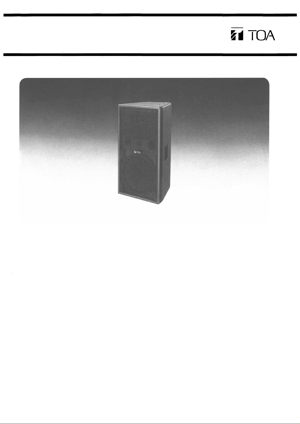
PROFESSIONAL SOUND SYSTEM
Operating Instructions
Speaker System
Model SF-60
GENERAL DESCRIPTION
The TOA SF-60 is a 3-way speaker system, a bass reflex
enclosure to be driven by 2-way multi-amplifier (biamplif i e r) , designed as permanent installation for professional applications in high-level sound reinforcement environments where high-efficiency and faithful reproduction
are required such as discos and in live sound reinf o r c e-
ment applications.
The SF-60 reproduces transcient response characteristics
in the low frequency range using a larger magnet th an
used for the 30cm (12") woofer assembled in the SF-30
speaker system.
The driver unit for the SF-60 is used the HFD-651 high
power driver unit improved for the system, and LE Series
Constant directivity (CD) horn ensures a unifor m sound
dispersion pattern (90° horizontal by 40° vertical).
The 2-way multi-amplifier driving system is adopted allowing each speaker unit to provide maximum performance,
and further the SF-60 is built in the passive cir cu it to c or rect time, phase and frequency response for obtaining the
best frequency response when the multi-amplifier is em-
ployed.
The passive type crossover between the driver and the
tweeter is adopted and its crossover frequency is set to
higher 10kHz. A high-tech crossover network of — 18dB/
octave slope at the tweeter is designed enabling to endure
high power input.
The tweeter level can be set with the High frequency level
control.
The fixing holes for easy ceiling suspension are provided
on top, bottom and both sides of an encl osure, and four
corners inside the enclosure are highly reinforced with L
type metals w ith W3/8" nuts.
The baffle fixed the horn and the tweeter can be turned to
either left-hand or right-hand direction to provide wide
directivity to the horizontal direction where the SF-60 is installed at either left-hand or right-hand direction.
Recessed type earring handles are provided on both sides
of the enclosure for installation or transportation, and the
enclosure is finished in gray, shock-resistant polyester
painting.
FEATURES
1. 3-way vented system driven by 2-way multi-amplifier
(bi-amplifier).
2. High power c apacity of 120 watts continuous pink
noise for low frequency and 80 watts for Mid/High fre quency.
3. 30cm (12") woofer using a larger magnet.
4. HFD-651 type high power driver with LE Series Constant directivity (CD) horn (90° horizontal 40° vertical).
5. Exponential horn tweeter.
6. Built in the passive circu it to c orrect time, phase and
frequency response for multi-amplifier driving.
7. Passive crossover between the driver and the tweeter
set to higher 10kHz.
8. High frequency level control for the tweeter.
9. Fixing nuts for ceiling suspension provided on top,
bottom and both side s of the enc losure.
10. The baffle fixed the horn and the tweeter can be
turned.
11. Recessed type carr ying handles provided on both
sides of the enclosure.
12. Removable punched metal front g rill.
Page 2
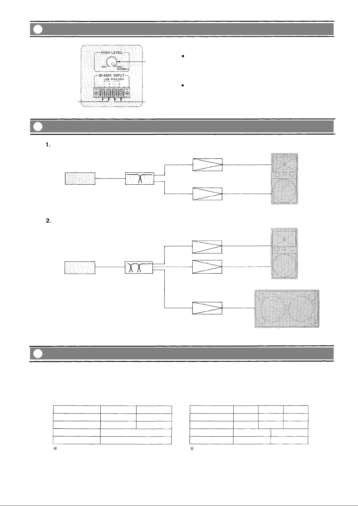
Input Panel
Input terminal of the SF-60 is divided into Low and Mid/High
frequencies as the SF-60 is a 2-way multi-amplifier driving
system.
Ensure to connect polarities ( + , –) of each amplifier output
cords to the speaker ter min als rightly.
Make the level setting according to the environmental con-
ditions, although almost flat frequency response is obtainable as long as the High frequency level control is set to
the NORMAL.
Low frequency
input terminal
High frequency
level control
Mid/High
frequency
input terminal
Connection Diagrams
SF-60 single system (2-way multi-amplifier driving system)
MID &
HIGH
Mixer/Preamplifier
Frequency dividing
network
LOW
Power amplifier
Combination system with the super-woofer (3-way multi-amplifier driving system)
HIGH
LOW
SF-60
MID &
HIGH
SF-60
LOW
Mixer/Preamplifier
HIGH
MID
Frequency dividing
network
LOW
Power amplifier
SW-46W-UL2
SW-46S-UL2
SW-38W-UL
SW-38S-UL, etc.
Frequency Dividing Network
Set each mode of the frequency dividing network as per the following tables. Best frequency response ensures as time
and phase are corrected with the built-in passive c i rc u i t.
1. SF-60 single system
(2-way multi-amplifier driving system)
LOW
Level
Phase
Crossover frequency
Slope
1 -5dB stands fo r a standard value when con-
nected the same amplifiers for LOW and HIGH
frequencies. Make the level setting a cc ording to
the environmental conditions at installation.
0dB
Normal
–12dB/octave (Butterworth)
–5dB*
1kHz
HIGH
1
Normal
2. Combination system with the super-woofer
(3-way multi-amplifier driving system)
LOW
Level
Phase
Crossover frequency
Slope
2 The crossover between LOW and MID frequency
range stands for typical one.
depending on
the system
Reverse*
80~125Hz*
–12dB/octave*
When Slope ch a r a c te ristics is changed, best
characteristics is obtainable by changing phase
of LOW frequency range into normal. Finally de-
cide the change at the time of measurement or
test listening.
2
MID
0dB
Normal
2
2
–12dB/octave
HIGH
–5dB
Normal
1kHz
Page 3
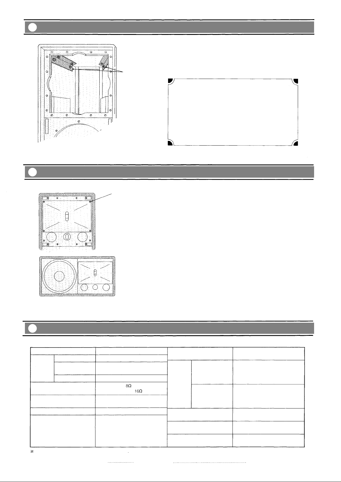
Installation
L type metals
with W3/8" nuts.
L ty p e metals with W3/8" nuts are provided at four corners inside the enclosure as shown in the figure. Nuts are located
just at back side of the fixing holes of the enclosure. Utilize
these fixing holes according to installation places of the
speaker. Refer to appearance diagram on the fixing holes.
Caution
The weight of SF-60 is approximately 39kg (86 Ib.). When
suspending this speaker to the ceiling, make sure to install
it after investigating struct ure of installation places, and
confirming that the suspending wir e s and hardware are
heavy-duty to this speaker.
Secure to tighten eyebolts etc. to fix the speaker.
TOA takes no responsibility for any accidents or injuries re-
sulting from the falling of the SF-60 due to incorrect in-
stallation.
Speaker Installation
g to Either Left-Hand or Right-Hand Direction Turnin
Fixing screws for the baffle (14 positions)
Turning the speaker to right-hand direction.
(Turning it to left-hand direction is also acceptable)
Specifications
If the SF-60 is turned to either left-hand or right-hand direction
according to environmental conditions, remove the baffle fixed
the horn and the tweeter and turn it by 90° to either left-hand
or right-hand direction to ensure wide directivity to the horizon-
tal direction as well as the installation at the normal di re c ti o n .
Remove the baffle with the following procedures.
1. Remove six screws fixed the front grill.
2. Remove 14 sc re ws of the baffle as shown in the figure .
3. Turn the baffle by 90° after taking the baffle from the enclosure. (Generally the tweeter position should be placed
downwards.)
4. Assemble the baffle with reverse procedures.
Enclosure
Low frequency
Speaker
Nominal impedance
Sensitivity
Frequency response
Crossover frequencies
Specifications are subject to change without notice
Mid frequency
High frequency
30cm (12") dia. cone speaker
CD horn (90° horizontal by 40°
vertical) plus compression driver
Horn type
Low frequency:
Mid/High frequency:
Low frequency: 98dB(1W/1m)
Mid/High frequency: 106dB(1W/1m)
Low to Mid frequency (Frequency
dividing network):
1kHz, –12dB/octave (Butterworth)
Mid to High frequency (built-in
passive network): 10kHz
Accessories: Operating instructions
Bass reflex type
60Hz~20kHz
1
Warranty card
High frequency level control
Low frequency
Power
handling
capacity
Mid/High frequency
Input connector
Weight
Finish
0~ –10dB (with an OFF position)
Continuous pink noise: 120W RMS
(Band-limited 50Hz~1kHz)
Continuous program : 360W
Continuous pink noise: 80W RMS
(Band-limited 1k~20kHz)
Continuous program : 240W
4P scr ew terminal
39kg (86 Ib)
Polyester in gray color
1
Page 4
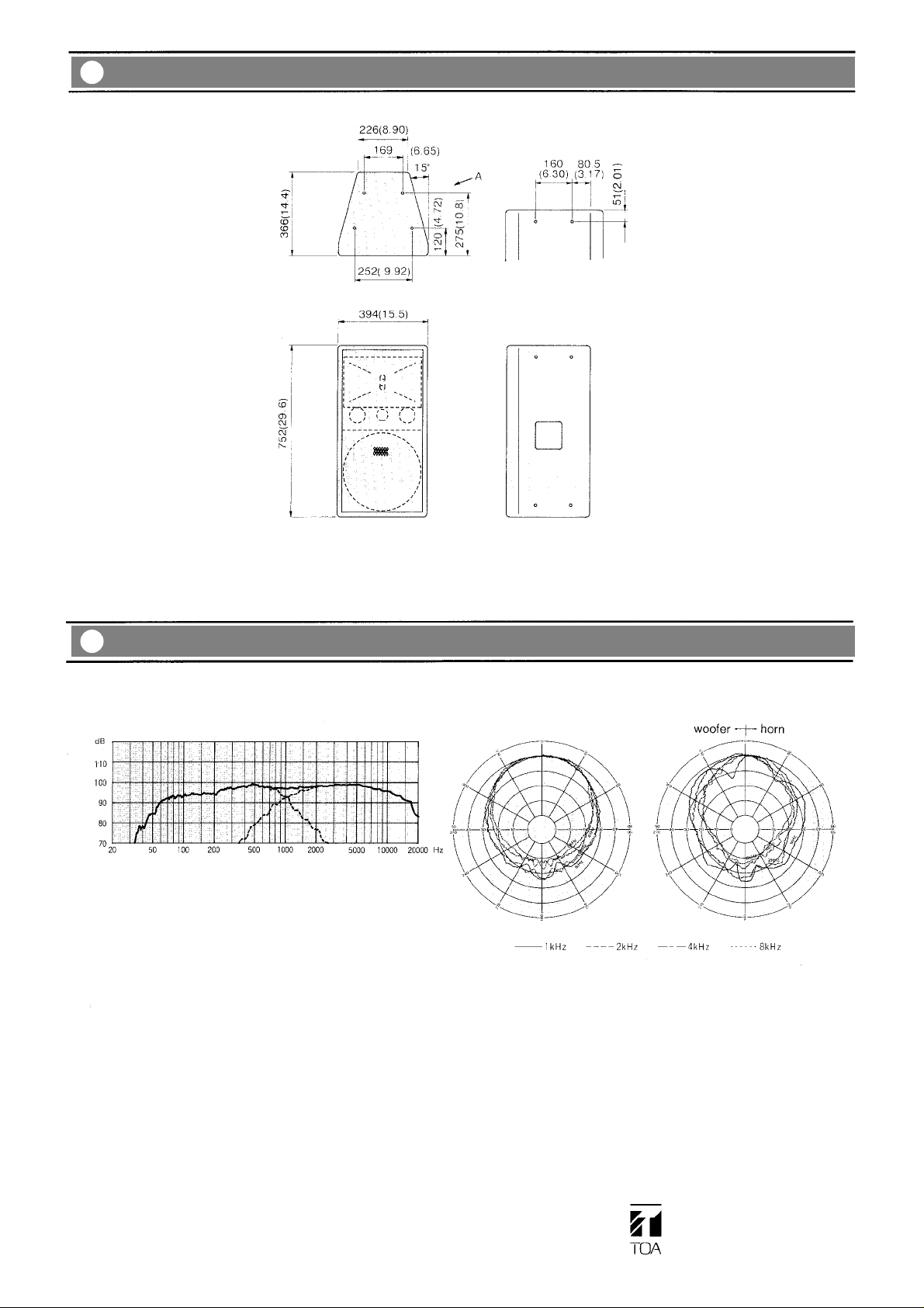
Appearance
View from A
mm
(in.)
Characteristic Diagrams
Frequency Response (1W/1m)
Frequency dividing network is set in status of the SF-60 single
system.
(1/3 Octave Pink Noise)
Polar Response (1W/4m)
Horizontal
Vertical
TOA Corporation
Printed in Japan
133-01-295-60
 Loading...