

Page 1
Trantec S5 Wireless Microphone Series
QUICK INSTALLATION GUIDE
Trantec S5 Wireless Microphone Series
Page 2

CONTENTS
Page
1. Introduction and system overview
2. Important safety instructions and getting started
3. Receiver set-up
4. Receiver frequency selection
5. Handheld transmitter set-up
6. Beltpack transmitter set-up
7. Operating hints and troubleshooting guide
8. Receiver rack mount kit
9. Technical speci cations
10. WEEE statement and warranty
INTRODUCTION
The Trantec S5 series represents our commitment to our customers by providing high-quality,
reliable wireless audio links using our considerable design expertise gained over many years
as a leading edge manufacturer.
We would like to thank you for purchasing this product and would like you to spend a few
moments studying this Quick Installation Guide, especially the safety instructions, before
going on to ‘read’ the full manual supplied on the CD Rom with this equipment.
S5 SERIES SYSTEM OVERVIEW
The S5 series is a professional UHF wireless microphone system with features including:
• 24 channel simultaneous operation (12 channel S5.3)
• 10 preset banks including 1 custom user. (9 Banks S5.3)
• True “dual receiver” diversity – to minimise drop-outs
• Intuitive LCD and operating system on both receiver and transmitter
• Infra-red programming for fast system set-up
• Software transmitter function locks
• Headphone monitoring as standard
• Both XLR (switchable mic and line) and 1⁄4” jack AF outputs
• AF processing menu (S5.5 only)
• Over 1400 customer selectable channels
• Fully integrated PC software monitoring facility via USB port
• All metal construction of receiver and transmitters
• Rack kit and front mounting antenna adaptors included (S5.5 only)
1
Page 3

SAFETY
Our aim is to supply you with a product that provides you with countless hours of trouble
free use. In order to achieve these goals we recommend the following:
• Keep the system away from direct sources of heat e.g. central heating
radiators, heaters and direct sunlight.
• Do not expose the unit to an environment where it could be splashed with
liquids as this may result in re or electric shocks.
• Should the transmitters not be used for extended periods of time we
recommend that the batteries are removed to avoid any potential leakage.
• Keep the system clean by using a slightly damp cloth. Never use household
cleaning agents or solvents.
• Avoid using or storing the system in damp conditions.
• Always use the AC power adaptor supplied with the receiver and always
disconnect from the AC outlet when not in use. And never remove the
external covers of the equipment, so as to expose the electronics, or modify
the unit in any way.
Should the covers be removed, or any other breach of the above instruction,
the warranty becomes null and void in addition to personal risk from burns
and/or electric shock.
When using the unit, should any of the following conditions occur, switch o the unit and
remove AC adaptor from AC outlet immediately and contact your nearest dealer.
• Smoke or unusual smell
• Water or foreign metallic object inside unit
• Damaged housings caused by physical damage
Never pull cord of AC adaptor, always grasp main body of unit when connecting/
disconnecting to AC power outlet
Never touch any part of the system during a thunderstorm, as this may result in severe
electric shock
GETTING STARTED
The S5 series is a high quality, fully featured wireless microphone system with many features
including an intuitive operating system. To enable you to get started we recommend you
initially set up the system as outlined in the next few pages.
2
Page 4
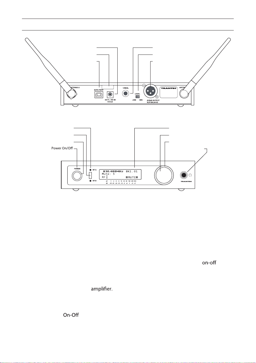
RECEIVER SET-UP
Rear View
tuptuo kcaj ”4/1 telni CD
hctiws eniL/ciM feiler niarts CD
tuptuo RLX trop BSU
Diversity switch A/B indicators
Infra-red port
Power switch indicator
LCD
Jog wheel
Mute indicator
Headphone output
Front View
1. Attach the supplied antennae (2) to the rear panel BNC antenna connectors as
shown in above illustration.
2. Connect the AC/DC adaptor into the DC inlet as marked on the rear panel
using the attached cable strain relief. Observe the front panel
surround is illuminated red.
3. Connect the rear panel AF output from either the 1/4” Jack or XLR to your
mixing console or
Note: the XLR balanced output can be switched
for either mic or line. The system can be also monitored from the headphone
socket using the “Jog-Wheel” to adjust Volume level.
switch
4. Switch
switch to “On” position and the receiver will default to initial
setting as per illustration above. (BK1.01)
The system is now ready for use.
3
Page 5

RECEIVER FREQUENCY SELECTION
5. Frequency selection options
• To change selected channel in BANK1:
Press “Jog-wheel” for 3 secs and enter the MAIN MENU. Press FREQ SELECT and go to
BANK setting, then select BANK1 and rotate jog wheel to select new channel, nally
press to ACCEPT to select new frequency. See attached frequency table.
• To change selected Bank:
Press “Jog-wheel” for 3 secs and enter the MAIN MENU. Press FREQ SELECT and go to
BANK setting, then select required BANK by rotating and pressing “Jog-Wheel” Select
new channel, nally press ACCEPT to select new frequency. Go to step 6 to program
transmitter via the Receiver Infra-red port.
• To change selected channel to a Custom single frequency. This option allows the
customer to select 1 of over 1400 available channels:
Press “Jog-wheel” for 3 secs and enter the MAIN MENU. Press FREQ SELECT and go to
SINGLE press EDIT and rotate and press “Jog-Wheel” to Select new frequency and User
Name. Press “Jog-Wheel” for 3 secs to EXIT then ACCEPT to select new custom frequency.
Go to step 6 to program transmitter via the Receiver infra-red port.
Please note: For S5.3 product the single user frequency will be added to Transmitter with
receiver Bank1. In the case of the S5.5 it will be added to the Custom “USER” bank. See
CD-ROM for more information.
6. Program Transmitter with Bank information via Receiver Infra-red port
Press “Jog-Wheel “ for 3 secs and enter MAIN MENU Press TX SET to enter TX SETTINGS
press FREQUENCY and align the Transmitter and Receiver Infra-red windows at a distance
of less than 15cm, press SEND and wait a few seconds. The Transmitter should now be
programmed and the Receiver will return to main display.
MISC SETTINGS
Mute/Squelch settings
• The S5 series uses sophisticated internal Mute functions including Pilot tone, Noise and
RSSI to prevent noise break through from external sources when the transmitter is in
the “OFF” position. The RSSI (Received signal strength) portion is user adjustable via
the RX SETTINGS MENU. To Access press “Jog-Wheel” for 3 secs and enter MAIN MENU
select and press RX SET then press MUTE and rotate “Jog-Wheel” to adjust between 1-10
then press. Please note high mute settings will decrease range and low mute settings
increase the interference potential. We recommend a setting of between 4-6.
Pilot Tone
The S5 series has the ability to disable the pilot tone as a means of either identifying
outside interference or allowing compatibility with non-pilot tone devices. To disable
Pilot Tone go to RX SETTINGS menu and select PILOT and remove “Dot” from the “Box”
then Exit menu.
4
Page 6

HANDHELD
TRANSMITTER SET-UP
End cap
Sleeve
Power ‘On’ Position
Infra-red port
Battery indicator
Up/Down
Frequency
Grille
1. Undo handheld sleeve by unscrewing the end cap anti-clockwise and then gently
sliding the sleeve to expose the LCD and Battery compartment. Place alkaline “AA”
cell into battery compartment observing the correct polarity.
2. Slide the On-O switch to the “On” position and observe the display is on and the
battery LED located in the end cap is illuminated. Check display indicates same
channel as receiver.
3. The receiver should now show received signal on its RF bargraphs and after 20
seconds the transmitter battery status.
4. Handheld Gain adjust
Turn on Transmitter and wait for the ashing “decimal point” on the LCD to stop
ashing. Press “Up” or “Down” buttons to increase or decrease head sensitivity in 3
stages. (0-2) “0” gain being for max SPL.
5. Frequency adjust
Turn on Transmitter and adjust frequency whilst “decimal point” is ashing (approx
6 secs) via the “Up” or “Down” buttons. When correct frequency is selected turn
transmitter “O ” then “On” to activate new selected channel.
6. Microphone Mute Switch
Incorporated in the Handheld end-cap is a Power ON LED and Audio Mute switch. To
mute the audio place switch towards LED.
5
Page 7

BELTPACK
Clip
Antenna
Lavalier mic
TRANSMITTER SET-UP
1. Insert battery into compartment by sliding end cap
forward and up. Ensure battery is inserted with the
correct polarity as shown.
2. Screw antenna into antenna socket as illustrated.
3. Plug Lavalier mic into Mini-XLR socket.
4. Place on-o switch to “On” position and observe
the display is on and the battery LED is illuminated.
Check display indicates same channel as receiver.
Antenna Bush
Power switch
Battery
compartment
LCD
POWER
ON OFF
Mini-XLR
Power LED
Infra-red port
Up/Down
Battery indicator
5. The receiver should now show received signal on its
RF bar graphs and after 20 seconds the transmitter
battery status.
6. Beltpack AF gain adjust. Turn on transmitter and
wait for the ashing “decimal point” on the LCD to
stop ashing. Press “Up” or “Down” buttons rmly to
increase or decrease AF gain with 10 steps with “0”
being minimum.
7. Frequency adjust
Turn on Transmitter and adjust frequency whilst
“decimal point” is ashing (approx 6 secs) via the
“Up” or “Down” buttons. When correct frequency is
selected turn transmitter “O ” then “On” to activate
new selected channel.
6
Page 8

OPERATING HINTS
To maximise operating performance Trantec recommends the following:
• Ensure good line of sight between receiver antenna and transmitter, avoid obstructions
e.g. concrete walls and metal structures.
• Ensure the receiver antenna is at least 3m (10 feet) away from the transmitters at all times.
• Always ensure transmitters are separated by at least 20cm.
• Never position the transmitter antenna directly against the body or the hand. This will
reduce the operating range.
• Ensure correct setting of Mute control for e ective control of interference whilst the
transmitter is turned o . Default is normally 4-5 but may need to increase with multichannel set-ups.
• Do not mix separate Banks in multi-channel set-ups.
• Use SCAN function to check for external interference. (See CD-ROM for more information)
• Set transmitter AF gain so the receiver VU indicates 0db with occasional peaks to +6dB.
• Keep Microphone/Instrument lead away from the antenna on the beltpack.
• Do not mix other brands of wireless microphone as Trantec cannot guarantee multichannel compatibility.
TROUBLESHOOTING
• No operation of Transmitter
Replace current battery with fresh correct Alkaline ‘AA’ type.
• No RF signal on receiver
Check transmitter and receiver are “tuned” to the same channel
• Poor range
Check mute level setting. For normal range we recommend a Mute setting of 4-5.
• AF Signal distorted
Check Receiver XLR mic-line switch for correct match to Mixer/Ampli er. Reduce gain of
Transmitter if VU meter shows over 6dB.
• AF Signal low level with high background noise
Adjust Transmitter gain so VU bar graph shows 0dB with 6dB peaks.
• External Head ampli ers not operating
Check for shorts in the leads and ensure Receiver PHANTOM PWR is switched on via RX
SETTINGS Menu.
• Receiver LCD contrast poor
Enter receiver RX SETTINGS Menu, select LCD and press then rotate “Jog-Wheel” to adjust
contrast. The receiver will automatically exit after a few seconds.
7
Page 9

S5 SERIES RACK MOUNT KIT
The rackmounting kit is supplied as standard with S5.5 systems, or is available as an
accessory for S5.3 systems.
POWER
RF A
RF B
uV 1 2 4 8 16 30 60 125 250 500
dB -36 -30 -24 -18 -12 -9 -3 0 +3 +6
19” Rack 2 x S5 series Receivers
1. Unscrew 3 x lid
retaining screws M3x6
from opposite sides of
each receiver case and
t angled brackets as
per illustration using
supplied screws.
3. Place remaining
joining strips x 2 on
the bottom side of the
receiver chassis using
M3x6 CSK screw as per
illustration.
POWER
RF A
RF B
uV 1 2 4 8 16 30 60 125 250 500
dB -36 -30 -24 -18 -12 -9 -3 0 +3 +6
2. Remove plastic
plugs from top of the
Receiver lid and place
metal joining strip in
lid slots and carefully
t M3x6 screws
(coloured black) as per
illustration.
19” rack 1 x S5 Series receiver with front mount antennae
8
4. Unscrew 3 x lid retaining screws M3x6 from
the left hand side of the chassis. (viewed
illustration 1 using the supplied screws.
5. Unscrew 3 x lid retaining screw M3x6
from the right hand side of the chassis and
t supplied long bracket using the supplied
screws.
6. Fit extension cables as per illustration into
front panel long bracket and tighten BNC
nut. Should front mount antennae not be
into spare holes.
t angled bracket as per
t plastic blanking plug (supplied)
Page 10

TECHNICAL SPECIFICATIONS
Overall System
Frequency Bands available: D1 863-865MHz D2 854-865MHz (S5.3 only)
D3 830-865MHz C1 794-830MHz C2 794-806MHz
B1 722-752MHz B2 740-752MHz A1 692-722MHz
E1 668-698MHz F1 636-668MHz G1 606-638MHz (S5.5 only)
G2 606-622MHz (S5.3 only)
RF Switching BW: 36MHz typical
RF grid spacing: 25kHz
RF Bandwidth: < 200kHz
AF Frequency response: 60Hz – 20kHz
AF Distortion: < 0.8% at nom deviation 22kHz
AF Dynamic range : >110dBA
AF Noise reduction: Trantec proprietary
Temperature range : -10ºC to +55ºC
noisrevnoc lauD LLP gnirutaef ytisreviD lauD :epyT
IF Freq: 1st IF 55.875MHz 2nd IF 10.7MHz
Sensitivity: < 1uV/12dB SINAD
Ist Image: >70dB
RSSI range: 10 steps 30dB range
Antenna Inputs: BNC 50 Ohm
AF switches: Low Cut – High Boost – Phase Reversal (S5.5 only)
AF Output level: XLR Line +15dBm max. XLR Mic -25dBm max. Unbal
.xam mBd9+ tekcos kcaj ”4⁄1
Antenna Phantom: 9V @ 60mA short-circuit protected on each RF port
10 Banks x 24 Channels (S5.5)
)3.5S( slennahC 21 x sknaB 9
Infra-Red Link: Range 15cm max.
Computer Interface: Computer monitoring via rear panel USB interface
Power Consumption: 300mA @ 12Vdc nominal
Power Supply: Single Alkaline “AA” cell 1.5V nom
Power consumption: Typically 120mA
Operating time: Typically 8-10hrs minimum
Controls:
Gain Range: Beltpack +2dBm to -20dBm in 10 steps
Handheld dimensions: 32mm x 250mm. Grille diameter 51mm. Weight 350g
Beltpack dimensions: 55mm x 80mm x 20mm. Weight 110g
, AF Gain Adjust, Frequency Adjust
)dlehdnaH( etuM FA
Bd6 spets 3 dlehdnaH
9
Page 11

CE DECLARATION OF CONFORMITY 0891
This equipment is in compliance with the essential requirements and other relevant provisions
of Directives 1999/5/EC, 89/336/EC or 73/23/EC.
IMPORTANT NOTICE. Before using this wireless microphone system please observe the
requirements of each country with respect to frequency allocations and individual licensing
requirements.
!
WEEE DECLARATION
This symbol indicates that this piece of electrical/electronic equipment must
be disposed of separately from normal waste at the end of its operational life.
Please dispose of this product by taking it to your local recycling or collection
point.
10
Page 12

D33-07-016-9D
URL: http://www.toa.jp/
 Loading...